

 From: AutoCAD Productivity Articles #123
Originally published: March 2013
Angular Dimensions
 The addition of Angular dimensions is pretty straightforward, but I also want to pass along some editing insights.
How to Add an Angular Dimension
Set the desired layer and dimension style to current first.
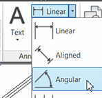
On the Home tab
 Annotation panel, expand the dimension flyout, then click Angular.
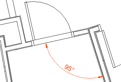
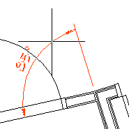 To find the angle between two lines—as shown in the figure with the doorway—pick the first line, and the prompt sequence will follow as shown here.
Select arc, circle, line, or <specify vertex>: [PICK]

Select second line: [PICK]

Specify dimension arc line location or [Mtext/Text/Angle/Quadrant]:
When positioning the dimension line location after picking two lines, move your cursor to any position defined by the vectors of the two lines, then specify the final location for the dimension line.
To dimension an arc, simply click on the arc, then position the dimension line.
Insights
To reposition the dimension line of an existing dimension, select it, then click in the grip on the dimension line and reposition it.
To edit the components of the dimension, select it, then right-click >Properties [or Ctrl +1].
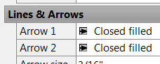
If you want different arrowheads, make the adjustment under the Lines & Arrows heading.
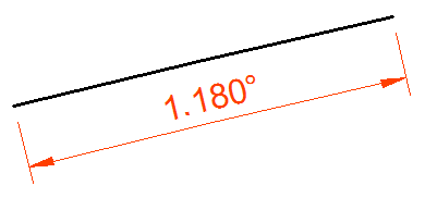
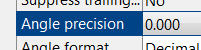
Under the Primary Units heading you can tweak the precision.
My apologies for not having any coverage over the last decade(!) on how to create a Dimension Style. Although it's on page 171 in AWB2, I promise to make amends in a future Corner.
See all the articles published in March 2013
See this article in the March 2013 Corner
Donate to CADTutor
If you found this article useful, you might like to consider making a donation. All content on this site is provided free of charge and we hope to keep it that way. However, running a site like CADTutor does cost money and you can help to improve the service and to guarantee its future by donating a small amount. We guess that you probably wouldn't miss $5.00 but it would make all the difference to us.
Note from Michael: I want to thank all of my customers for continuing to retain my training services (some for over three decades!) and let you know your donations do not go to me personally, but to the ongoing maintenance of the CADTutor ship as a whole and to support the yeoman efforts of my friend and CADTutor captain, David Watson, to whom I am grateful for this monthly opportunity to share a few AutoCAD insights.


