Search the Community
Showing results for tags 'dimension style'.
Found 7 results
-

Problem with macro for creating several dimension styles
Sandervp posted a topic in The CUI, Hatches, Linetypes, Scripts & Macros
Hello everybody, I've created a macro for creating different dimension styles for different scales. We are using these dimension styles in our company. It works well if I use it in a new, empty drawing. But if I use it in an excisting drawing with a dimension style with the same name, I have got a problem..... I'll see this in the command line; "Enter name for new dimension style or [?]: "scale 20" That name is already in use, redefine it? :_dimclrd Invalid option keyword. That name is already in use, redefine it? :" "_dimclrd" should be the next command in the macro, but because "scale 20" is already in use, I need to do some other commands first. AutoCad stops with this macro at this point. If the first dimension style, which the macro should be create, already in use, the other dimension styles shall not be create. Is there a possibility/ sollution to change my macro so he creates every dimension style what he supposed to do? Also if one or more dimension styles already excist? The reason why; if you delete a dimension style because you think; "I don't need him any more." But you're wrong. Or somebody else goes further with the drawing and needs to draw something with another scale. You need to copy the 'wanted' dimension style from another (new/ excisting) drawing. Could somebody help me? This is the whole macro; ^C^C_dimclrd;1;dimltype;continuous;_dimlwd;-1;_dimdle;1.25;_dimdli;1.25;_dimclre;1;_dimltex1;continuous;_dimltex2;continuous;_dimlwe;-1;_dimexe;1.25;_dimexo;1.25;_dimblk;"";_dimldrblk;"";_dimasz;2;_dimcen;0;-style;;iso.shx;a;;;0;;;;;no;_dimtxsty;standard;_Dimclrt;2;_dimtfill;1;_dimtxt;1.8;_dimtad;1;_dimgap;1;_dimtoh;off;_dimtih;off;_dimtmove;0;_dimscale;1;_dimdec;0;_dimzin;0;_dimtolj;0;_dimse1;off;_dimse2;off;_dimrnd;5;_dimtofl;on;-dimstyle;s;"scale 1";_dimclrd;1;dimltype;continuous;_dimlwd;-1;_dimdle;1.25;_dimdli;1.25;_dimclre;1;_dimltex1;continuous;_dimltex2;continuous;_dimlwe;-1;_dimexe;1.25;_dimexo;1.25;_dimblk;"";_dimldrblk;"";_dimasz;2;_dimcen;0;-style;;iso.shx;a;;;0;;;;;no;_dimtxsty;standard;_Dimclrt;2;_dimtfill;1;_dimtxt;1.8;_dimtad;1;_dimgap;1;_dimtoh;off;_dimtih;off;_dimtmove;0;_dimscale;2;_dimdec;0;_dimzin;0;_dimtolj;0;_dimse1;off;_dimse2;off;_dimrnd;5;_dimtofl;on;-dimstyle;s;"scale 2";_dimclrd;1;dimltype;continuous;_dimlwd;-1;_dimdle;1.25;_dimdli;1.25;_dimclre;1;_dimltex1;continuous;_dimltex2;continuous;_dimlwe;-1;_dimexe;1.25;_dimexo;1.25;_dimblk;"";_dimldrblk;"";_dimasz;2;_dimcen;0;-style;;iso.shx;a;;;0;;;;;no;_dimtxsty;standard;_Dimclrt;2;_dimtfill;1;_dimtxt;1.8;_dimtad;1;_dimgap;1;_dimtoh;off;_dimtih;off;_dimtmove;0;_dimscale;10;_dimdec;0;_dimzin;0;_dimtolj;0;_dimse1;off;_dimse2;off;_dimrnd;5;_dimtofl;on;-dimstyle;s;"scale 10";_dimclrd;1;dimltype;continuous;_dimlwd;-1;_dimdle;1.25;_dimdli;1.25;_dimclre;1;_dimltex1;continuous;_dimltex2;continuous;_dimlwe;-1;_dimexe;1.25;_dimexo;1.25;_dimblk;"";_dimldrblk;"";_dimasz;2;_dimcen;0;-style;;iso.shx;a;;;0;;;;;no;_dimtxsty;standard;_Dimclrt;2;_dimtfill;1;_dimtxt;1.8;_dimtad;1;_dimgap;1;_dimtoh;off;_dimtih;off;_dimtmove;0;_dimscale;20;_dimdec;0;_dimzin;0;_dimtolj;0;_dimse1;off;_dimse2;off;_dimrnd;5;_dimtofl;on;-dimstyle;s;"scale 20";_dimclrd;1;dimltype;continuous;_dimlwd;-1;_dimdle;1.25;_dimdli;1.25;_dimclre;1;_dimltex1;continuous;_dimltex2;continuous;_dimlwe;-1;_dimexe;1.25;_dimexo;1.25;_dimblk;"";_dimldrblk;"";_dimasz;2;_dimcen;0;-style;;iso.shx;a;;;0;;;;;no;_dimtxsty;standard;_Dimclrt;2;_dimtfill;1;_dimtxt;1.8;_dimtad;1;_dimgap;1;_dimtoh;off;_dimtih;off;_dimtmove;0;_dimscale;50;_dimdec;0;_dimzin;0;_dimtolj;0;_dimse1;off;_dimse2;off;_dimrnd;5;_dimtofl;on;-dimstyle;s;"scale 50";_dimclrd;1;dimltype;continuous;_dimlwd;-1;_dimdle;1.25;_dimdli;1.25;_dimclre;1;_dimltex1;continuous;_dimltex2;continuous;_dimlwe;-1;_dimexe;1.25;_dimexo;1.25;_dimblk;"";_dimldrblk;"";_dimasz;2;_dimcen;0;-style;;iso.shx;a;;;0;;;;;no;_dimtxsty;standard;_Dimclrt;2;_dimtfill;1;_dimtxt;1.8;_dimtad;1;_dimgap;1;_dimtoh;off;_dimtih;off;_dimtmove;0;_dimscale;100;_dimdec;0;_dimzin;0;_dimtolj;0;_dimse1;off;_dimse2;off;_dimrnd;5;_dimtofl;on;-dimstyle;s;"scale 100"; Thanks -

Continuous Running Dimensions, is it possible?
e_anders3 posted a topic in AutoCAD 2D Drafting, Object Properties & Interface
Is there a way to create a continuous dimension line that uses running dimensions instead individual segments? I know that you can do baseline measurement but I received a request to have the dimensions look like a continuous dimension line, but be running dimensions. I'm aware of UCS -> cordinate -> baseline (dimension) That's pretty much what I want but I want it to be a line with arrows and what not. I'm not even sure if it's possible. I've attached an image of what I'm looking for if it helps. Thanks!
-
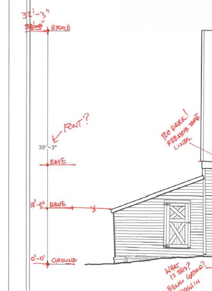
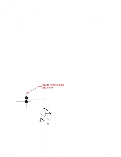
I work for a firm that has horrible drafting conventions - i.e. exploded dimensions, etc. So, I am *trying* to match their crappy hand-drawn dimension style with a standard style. My question is how to remove the lines perpendicular to the extension lines that extend outside of the arrows when the dimension is very tight. See the attached sketch. I DO NOT want to have to explode the dimensions to make this stupid change I am being asked to do. Also, is there any way to add a leader arrow on the dimension text leader? Thanks!
-

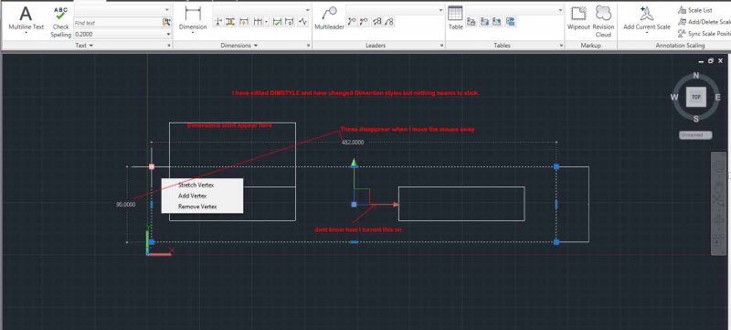
How do I control display of dimensions?
Vagulus posted a topic in AutoCAD 2D Drafting, Object Properties & Interface
Having drawn this spacer for the tutorial I am following, I decided to add the dimensions. The dimension shown here is 200mm but you wouldn't know that. How do I set the dimensions so I can see the arrowheads and read the text?
-

How to control lineweight i dimension?
jrn posted a topic in AutoCAD 2D Drafting, Object Properties & Interface
When drawing in .stb-file (with layer dependent plot style, plotting in monochrome) and when Dimension Text Style is set to Romans (must not be changed), then how to change line weight of Lines and Text separately? Please help. Thanks. -
This used to work, then my computer dies and AutoCad was reinstalled. I am trying to dimension some cut-outs in a 19" rack panel. I can dimension them, it shows the correct dimensions but then when I hit enter it wont save the dimensions. I've gone into DIMSTYLE and everything looks fine but I cant get this simple task to work. Any help would be much appreciated.
-

Dimnsion style changes without dimension style being changed
Epicurwin posted a topic in AutoCAD 2D Drafting, Object Properties & Interface
I'm working on a drawing that was converted into cad and it seems like every dimension has its own style. When I copy use the move comand or try to change the dimension the text changes from being above the dimension line to centered and the text gets closer together horizontally. When I compare a copied dimension to the original it has all the same properties including the text pos vert still being above text. The actual dimension style hasn't changed at all but what is showing up on screen is different. Anyone have this problem before? Here a image showing three dimensions with the same properties, the top 2'-10" is what it should look like, the bottom is what it looks like when I copied it and the 1'-2" is when I make a new dimension.