Search the Community
Showing results for tags 'loft'.
Found 14 results
-

How to select a "loft" surface via lisp to thicken
Hachi posted a topic in AutoLISP, Visual LISP & DCL
Hey guys! I'm trying to write a lisp that creates a 3D reducer. Once I create the 3D surface via command "_Loft" it remains to create a 3d solid body with the "thicken" command. I can't select the 3D loft surface. Can anyone help with this? Thanks in advance for the answers! Here is my code: (defun c:ccs (/ DK DN L P1 P2 P3 P4 RK RN S NS) (setq Dn (getreal "Adja meg a nagyobb vezeték külső átmérőjét:")) ; Give me the biger pipe diameter (setq Dk (getreal "Adja meg a kisebb vezeték átmérőt:")); give me the reduced diameter (setq L (getreal "Adja meg az átmenet hosszát:")); give me the length in which have to be reduced (setq s (getreal "Adja meg a falvastagságot:")); give me the thickness of the pipe (setq Rn (/ Dn 2)) (setq Rk (/ Dk 2)) (setq ns (min s (- 1))) (setq p1 '(0 0 0)) (setq p2 (list 0 0 L)) (setq p3 (polar p1 0 Rn)) (setq p4 (polar p2 0 Rk)) (setq p5 (polar p3 (/ pi 2) Dn)) (setq p6 (polar p1 pi Dn)) (command "_Circle" p1 Rn "") (command "_Zoom" "_All" "") (command "_Circle" p2 Rk "") (command "_Zoom" "_All" "") (command "_loft" p3 p4 "" "") (command "_select" p5 p6 "") ;(command "_THICKEN" ns "") (princ) ) -
In Inventor, I wish to model a piece of metal. I wish to create a loft between two (2) sketches, and then unfold the item. I am having trouble and I need some assistance. Even though my sketch geometry had correct material thickness and bend radius, consistent with the sheet metal rule, the part won't unfold to flat pattern. Why?? -MR
-
I have the beginning and ending elements of a tube. It seems like I should be able to loft the cross sections to create a tapered and offset tube. With rails selected I sometimes get the inner diameter to project in a straight line between the surfaces, but when I click OK I get an error, create loft feature failed. One time I was able to select the centerline as a path and saw the inner surface follow the curve, but usually when I click on the centerline icon in the loft window the preview of the loft disappears. I really want the whole tube cross section to loft, not just the inner and outer surfaces. End goal is a file for a 3D printer to build the tube.Intake Hose left and Right ends.ipt
-
Hello! I'm trying to make a model of a spinning top shown in the attached image, and I'm having trouble doing it, even though I think I know what each individual step should be. I've made a profile of one "fan blade" at its widest point, a tapered helix that it should follow, and a small circle at the narrowest point of the helix (the fan blade and the circle are separate sketches). I'm trying to Loft the fan blade around the helix into the circle, and although SW shows the preview, it won't complete the Loft. Also, the fanblade does not rotate around the helix axis as it gets Lofted around as I want it to. I thought maybe I should create intermediate Loft stages, but how do I rotate a sketch around some axis? Another approach I tried, was to just Sweep the blade around the helix - and that worked, however I wasn't able to apply "circular pattern" to that feature - it would show the preview, but when I hit accept nothing happens. Is there a tutorial on how to do something like this step by step? I'm missing some details and I would like to learn. Thanks guys!

-
i'm watching a video on youtube of a how to draw a helicopter blade, i understand what is going on in the video, but there is one point i can't follow. right when . I did exactly everything he did until that point, where i can't target the open loop(the line), instead it targets the sketch(3 lines connected to each other). I attached my last progress file blade5.SLDPRT .. i'm using solidworks 2015 sp2.1
-

Object made with Loft cannot be exported to Flow Design
Hagel123 posted a topic in AutoCAD 3D Modelling & Rendering
At the moment I am busy trying to create a Blended Wing Body. To test my designs I use Autodesk Flow Design. Unfortunately, this program does not accept .dwg so it is needed to change these files to .slt. The problem I encountered while doing this is that objects made with the Loft functions will not appear in the simulator and cannot change into .slt in contrary to the other AutoCAD-made objects which are transferring successfully. Does someone know how I can change these Loft-objects to non-Loft objects in order to successfully change them to .slt? -
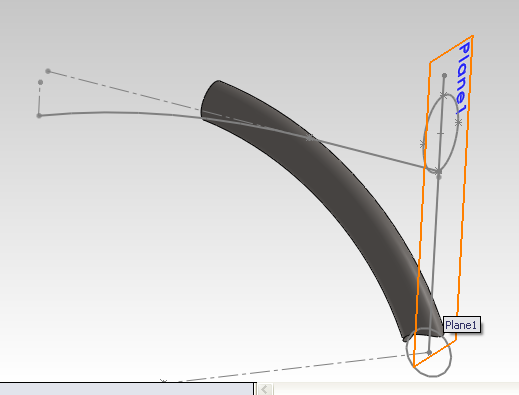
Hello; I have an unusual difficulty to ask help with. I've got a tube which is connected to another tube at an angle and I have to show the tube cut to fit. The ellipse is the shape that I need to extrude straight and then along the shown curve. I tried at first creating a loft (thinking I could build them together and break afterwards. However the loft didn't work. So I tried creating it as a surface, but the lofted surface wouldn't work either. Does anyone know why lofting is acting strangely? btw -this is SW2011 curved-downtube.SLDPRT
-

3D Splitting and lofting of a metal plate
paisis123 posted a topic in AutoCAD 3D Modelling & Rendering
Hello guys. I been requested by my company to start a bit in 3D work. (after 8 months of working here.) Anyway, to sum up my problem, I will break it down for you so this issue can be resolved and allow others to learn from this post as well. 1. Summary on what I'm trying to do. Basically we are trying to make a 3D plate (in this case a 2" thick piece of steel) and have a 3D hollow shape inside. Its split into Top and bottom, as shown as the below picture. I have tried the loft command (which I just learned off within the past hour or so) and it indeed works. But I wish to use its as the opposite, where the middle is hollow and the rest is a solid object. I have tried the loft command (which I just learned off within the past hour or so) and it indeed works. But for the life of me does not know how to get it as one big object with the middle shape hollow. Am i missing a step or is it another command completely? Also, once the object has been created, I want to split the object on its X axis mulitple times, almost like an exploded view. Each split will have its own set of top and bottom orifices which will represent multiple plates. Is there a way to do that? Also is there a way to gain and separate the top and bottoms of these newly split plates? Here is the drawing file as well to work on -> 3D-MK1.dwg
-
i have lofted two different triangles made by using line. they lofted fine but it is see through, how do i make it opaque? i use inventor 2013
-

Creating Terrain from 3D polyline (Loft?)
janetengo7 posted a topic in AutoCAD 3D Modelling & Rendering
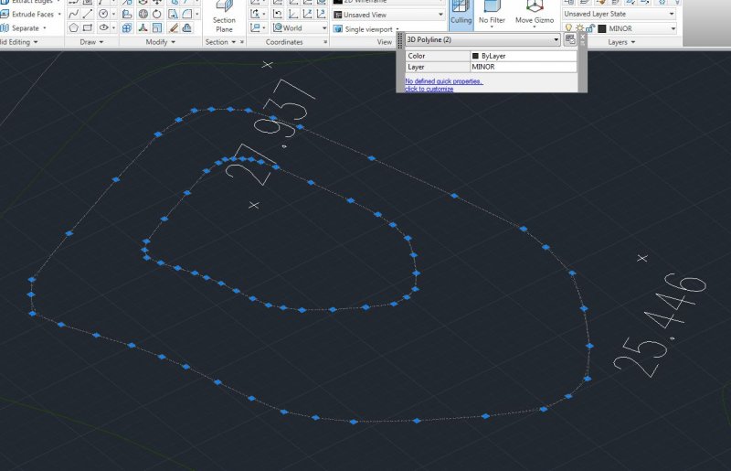
Hi, I'm new to this forum as well as Autocad. I'm currently facing this problem of lofting/elevating the drawing. The drawing had all the 3D polyline and I need to join them. I have no problem joining a 2D polyline, but now i'm facing this problem. see attached. Please help~~ Much thanks in advance!
-
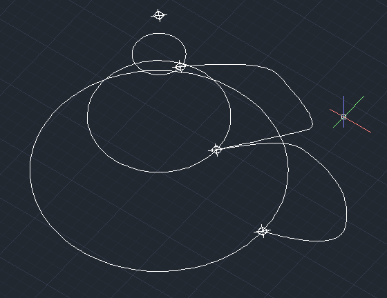
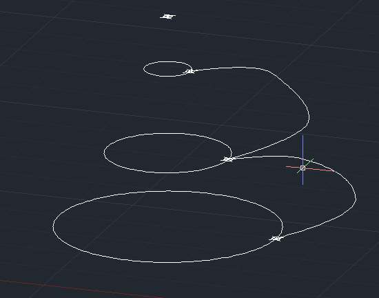
Hi, Here I have two views of my structure that I'm trying to LOFT/Extrude, but with the guides I've drawn. Objective: To LOFT the circles together (or extrude them) with the polyline as a guide, and I assume the effect of the guide would be on all sides (ie 360 degrees around the circle would exhibit the same guide effect) Problem For some reason I can LOFT, but I can't use the POLYLINE as a guide, like it says "it's invalid":glare: I'm trying to make the shape of a cartoon POO (crap)... Thanks a lot guys for your time! @Remark: I appreaciate your answer, but with Revolve I will get a uniform surface, which will still work in my case, but if I wanted to create a surface that also changes in the radial direction (the revolve direction), "revolve" wouldn't work. @SLW210: Thank you, but even if I choose "Path" it still wouldn't work @nestly: Thank you I will definitely review the limitations to see if I can work my way around. Hoping to see some more comments if anyone has an idea!
-

AutoCad2011 Lofting Problem: Guides doesn't work
Arvid93 posted a topic in AutoCAD 3D Modelling & Rendering
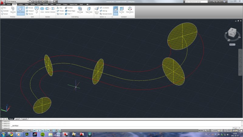
I try to loft (solid) a couple of circles with varying diameter and when I choose the guides (red) it tells me "The selected entities are not valid.". I cant understand why it doesn't work. Anyone wanna take a look at it? Lofting.dwg
-
'ello, I'm a fairly new user of Inventor 2009 and I've run into a problem I have no idea how to get around. I've created to separate shelled loft parts that that have no volume-they reflect two different surveys of interior tunnel walls. I've placed both of these parts into an assembly to make a representation of the tunnel, but then when I go to put it in .dwg format, nothing! No matter what view I select it's just an empty box. When I just put the part itself into a drawing it works fine, something about putting it in the assembly is making it not translate over? Has anyone else had this or know how to get around it?? Any help would be greatly, GREATLY, appreciated!!
-
Can a part of a loft profile be made with a 3D polyine? I have seen profiles done using 2D ellipses, but I just want to see if at least one of the profiles can be done 3 dimensionally, or if that would mess up the command? Thanks for the help.


.jpg.7cbb90048bb1b34a73db6d6b2b3c96e4.jpg)
.jpg.dd560eb19c1fb867645719d66f15ba7d.jpg)