Search the Community
Showing results for tags 'rotate'.
-

Dynamic Blocks | Rotate Parallel Lines and Maintain Perpendicular Distance
bluebravo posted a topic in AutoCAD Drawing Management & Output
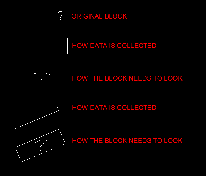
Hello! Quick FYI: (1) I am a brand new forum member, but I have looked up CAD issues on CADTutor various times! (2) I believe myself to be an intermediate level skilled CAD user Goal: I am trying to create a dynamic block of plywood that can be rotated, lengthened, and thickened. The block would contain two parallel lines and a hatch between them. I think I can achieve the lengthening with linear stretch and the thickening I can probably figure out, but I do need help with the rotation! Please see image for desired result: I have tried chained rotation actions, but the lines do not remain the same distance apart. Also, when all objects are rotated about the origin, the top line extrudes horizontally past the bottom (origin) which I do not want. I am not sure how wordy to be with my explanation, so I will leave it at this for now. Let me know if I need to provide anything else!
-

Rotating multiple objects in place
CDM-ARCH posted a topic in AutoCAD 2D Drafting, Object Properties & Interface
I have multiple abbreviations in drawings such as "FA" for first aid and need to have them all oriented in a different direction. Is there a way to select all of them and have them rotate in place or do I need to do each one individually? -
This mtext won't rotate. When I use the rotate command, the text moves around a point, but stays right side up the whole time. I remember this happening with xrefs as well. Anyone know what's happening here?
-

Dynamic block rotation (with fillet)
adylon posted a topic in AutoCAD 2D Drafting, Object Properties & Interface
Hi everyone, I am trying to make a block with a rotation parameter. Two lines connected with a rounded corner. One line you can rotate. The arc follows the rotation but should adjust accordingly to the angle between the lines, the radius stays constant. Can someone give me a kickstart to solve this?? RotationBlock_withFillet.dwg -

Insert a block at multiple points or lines and scale
grouch19 posted a topic in AutoLISP, Visual LISP & DCL
G'day all I'm working on and editing a mapping project from photogrammetry. I have a block which indicates a square manhole cover. (File is attached to this post) My project area has hundreds of these manholes and my client needs each of them scaled and rotated to fit the exact size of the manhole. I had been manually doing this with the help of an ECW image in the background. But the process is rather tedious and not all that accurate. My operators can pick up a three point string showing the height and length of the manhole. Some manholes are square and some are rectangular. I have a few lisp routines that get the block in there. The block insertion point comes in at the first plotted point as required. Is there any similar LISP that will insert the attached block dwg file at the first point collected and scale it based on the 2nd and third point whilst keeping the elevation heights? I've attached two dwg files... One is the block itself and one is a diagram with a better explanation. I've also added a screen shot of what is required. Any help would be appreciated Cheers guys Manhole.dwg BlockSample.dwg
-
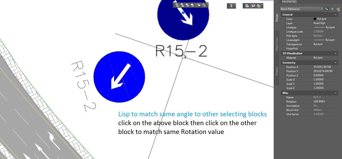
Lisp to match rotation angel to another block (first click on a block that rotation pick then another click on another block apply)
-

LISP to rotate group of Multileaders about end of leader
Edgtrimmer posted a topic in AutoLISP, Visual LISP & DCL
Had to rotate a floorplan 180 along with all multileaders and text. I can easily select multileaders and change angle to 0 in Properties but text ends up on top of leader or in wrong position relative to leader. It would be great to have a command able to select a group of multileaders and step through them rotating them a desired angle about the end of the leader. Any takers? Thanks! -

Rotating Text around base point based on azimuth of 3D polyline
cartographer posted a topic in AutoLISP, Visual LISP & DCL
Hi guys & gals, I came across a very repetitive problem. While working with a certain type of software data is output to *.dxf as set of 3D polylines and text. From the level of software I work with, I cannot configure any text formatting details. Hence an idea to ask You few questions. 1. Is there any way of rotating text based on azimuth of a 3Dpolyline which lies within 0.3m distance from the text base? Did someone ever came across LISP of this type ? 2. is there any other (more effective) way than OVERKILL to get a rid of duplicated text ? Thank you in advance ! Regards, Adam, Geophysicist.
-
Hello everyone. I am working with a code to copy object (s) and paste with rotation using the same base point as the axis of rotation. What I can't do is create a while cycle to be able to make multiple copies and rotate. I could only do it once. If someone helps me a little I would be very grateful. (defun c:cr (/ ss p1 p2 p3) (setq ss (ssget)) (command "copy" ss "" "0" "0") (setq p1 (getpoint "\n base Point: ")) (setq p2 (getpoint "\n destination point: ")) (command "move" ss "" p1 p2) (setq p3 (getpoint "\n reference point: ")) (command "rotate" ss "" p2 "R" "@" p3 pause) )
-

Dynamic block - Door: Zero value linear parameter bug, stretch after flip flaw
Jooogyerek posted a topic in AutoCAD Drawing Management & Output
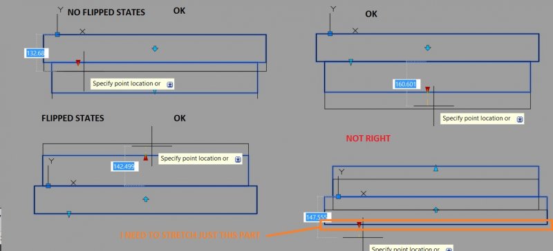
Hi for everyone. I made a dynamic block for doors by combining some tricks learnt from other dynamic block. By the way thanks for the shared ideas. I am almost satisfied with the result but I still have two things to figure out.: 1. If the block is rotated by a rotate action and I enter a zero value for an another linear parameter it gets messed up. The grip arrow turns horizontal or vertical (following the UCS not the current rotation) and if I re-enter a non-zero value it gets more messed up. 2. The other issue is harder to explain.: The block haves two rectangles, two linear parameters and one flip parameter. The first linear parameter stretches the shorter rectangle, the second stretches the longer one and stretch/moves the shorter one and also moves the flip parameter halfway. It works great as long as I don’t use the second linear parameter AFTER I used the flip parameter. I want to keep stretching the longer rectangle always downward and keep the sides of the rectangles col-linear but if I flip the short rectangle... well try it out. You will know what I mean. I include the current version of the dynamic door block and two other simplified block focusing just on the problems. PROBLEM 2.dwg PROBLEM 1.dwg DVERE A LA VIKTOR v13.dwg
-
Working on a utility to rotate polar type array half the angle between items to create a stagger effect of multiple concentric arrays. As far as my research turned up, there is no lisp property for the center point of the array. An array seems to be an anonymous block who's insertion point is always WCS (0 0 0), so if I apply a rotation property it does it from that point and not center point of array. Solution 1: Select the array, highlight grips with (sssetfirst), (getpoint) the center grip the rotate from that point... [not crazy about this option] Solution 2: Select the array, run the list command and extract the center point property from the log file [works marginally as the precision is only 8 decimal places so it ends up displacing it slightly] Any ideas?
-
Hello all, I would like to know if anybody has any bright ideas about a problem I face when drawing building elevations in 3D. I use 3D polylines to survey a facade on site. When back in the office I get an output of a 3D polyline with a point and node at each surveyed point. The point is aligned to 3d *top* view. I then rotate the current view aligned to the required building facade. My question is twofold: 1) Is there a way of rotating the point to see the point style in the current view? 2) As my point information plots in 3D as point, point number, and elevation is there a lisp routine to rotate the point number text and level text about the centre of the point to present as 'correct' in the current view? I don't expect miracles or written LISP routines but a couple of pointers would be really appreciated. Lownote
-

Dynamic block does not work in a new drawing
Faouweb posted a topic in AutoCAD 2D Drafting, Object Properties & Interface
Hi, I created some Dynamic Block and inserted them in a new Tool Palettes, but when I want to insert them in a new drawing the Block looses all the dynamic thing like rotation, flip... How can I solve this problem? Thank you. PID-SYMBOL.dwg -

Dynamic Block Copy/Rotate or Polar Array?
rhgrafix posted a topic in AutoCAD 2D Drafting, Object Properties & Interface
I am trying to make a dynamic block to somewhat mimic the 3D Revolve command, since I can't Sweep or Revolve 3D entities in the dynamic block, I want to fake it by making a revolved curved piece that travels 5° increments of a circle at a time, the dynamic part would be to make it copy itself end to end using the same axis as the part. I tried polar and rotate, they won't copy AND rotate, they always stay in a straight line. Anyone know how to do this? Thanks! R.L. Hamm -

Rotating multiple objects / text in 3d around their insertion point
tmduk posted a topic in AutoLISP, Visual LISP & DCL
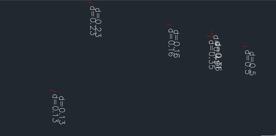
Hi there all First post and it's a request for help (although been a long time lurker) I've got a 3d drawing that has a load of levels in 3d positions with text displaying the height value. These are all orientated and readable in plan view. I want to create some sections using the 3d information, and what I would like to work out is the best way to manipulate the level cross (block) and associated text so that it is rotated to a side on section view. (in model space not just in a paper space viewport) I've tried using the rotate3d command on mass and can't quite get the results I'm after, basically it rotates the text so that it is now readable in the section but when selecting multiple items it rotates the whole lot around one datum rather than rotating each item around it's own insertion / justification point. in the above image, to the left is what I'm starting with levels (red) in 3d - next is the result I get from using the command rotate3d (levels in white) when they are selected in one go. the text is rotated so that it's legible but has moved away from the 3d polyline - the 2 to the right show what i'm aiming for, having manually moved them to their representative points and then rotated, however there's gonna be quite a few to rotate and shift along different sections, so it would be good to have this a bit more automated any suggestions? am I not using rotate3d to it's full potential or is this something that would need to be solved with a lisp routine? picking a temp ucs along the section line and then selecting the relative objects to rotate thanks in advance -

Cannot rotate copied lines by changing the angle of degree in properties
djleon posted a topic in AutoCAD Beginners' Area
I did an F1 search in CAD and couldn't find the answer. I have be remodeling a floor plan and notice that when I copy a room or single line, I am unable to change the angle in properties. The calculator shows up in the properties angle cell, but when it's there, It doesn't work. Is there a setting to change this? Thank you. -
Hello internet, Chelsea here. So for my graphics assignment I am making a lego character (to be specific Unikitty from the Lego Movie). I'm going pretty well so far, but I want to rotate the head along the neck in the assembly so that it isnt as straight as it is right now. Maybe like a 30 degree turn from where it is so it looks like it is looking to the side (not fully) instead of straight ahead. HOW? Thanks! Also, this assignment is due in two days *facepalm*
-
I am pulling my hair out..... First I insert a tiff fila and when I try to rotate afterwords it become transparent or the image quality denigrates. I have tried image quality command, and looked in setting to see if something changed like the background transparency but to no avail.
-

Xref - rotate - causing fatal error in AutocadLT 2015
zwei_kat posted a topic in AutoCAD Bugs, Error Messages & Quirks
We have an ongoing problem running AutocadLT2015 with Xrefs causing fatal errors accross a few computers in our office. What happens is: Error occurs after deploying an existing acad dwg into the 2015 file (which saves as 2013). Select Xref, Clip Xref, and then rotate Xreflaunches the fatal launch error 'runtime error' R6025 - pure virtual function call We have tried: Save out to a DXF file, re-launch Acad, and audit always yields 81 errors (fixed), re save as a dwg and re-launch. But the problem keeps on happening! -
Hi, I’m experiencing a particularly perplexing bug/issue. I am attempting to perform the mvsetup command (as I have done many times before without issue). I go through the following steps via the command line: Firstly – making sure I am in paper space in the view port I want to carry out the mvsetup command. 1. ‘mvsetup’ 2. ‘A’ 3. ‘R’ 4. ‘select my point of rotation’ 5. ‘enter my numeric value for angle of rotation’ Normally when I perform the above steps the viewport rotates the view to the angle I have entered. On this occasion (and I cannot duplicate this in any other drawing), the screen flickers and you briefly see the view rotating, but then it flickers back to its original state. In the command line the following appears: Command: _.UNDO Current settings: Auto = off, Control = All, Combine = Yes, Layer = Yes Enter the number of operations to undo or [Auto/Control/Begin/End/Mark/Back] : _EN Command: I have copied the drawing objects into a new drawing, created a new layout and viewport and the mvsetup command works fine. However this is not a practical solution because to do this properly would result in too much time being spent reformatting all the sheets associated with the drawing. Any help that anyone can offer would be greatly appreciated. Thanks in advance Gman1979 Windows 7 Professional 64-bit AutoCAD 2015 64-bit 8GB Ram Intel CORE i7
-
I have a drawing with a parcel. I want one of the lines to be straight across with no angle. On the older version of cadd I was able to align a view port to a line. Is there a way to do this with Civil 3D 2015? If so, how would I go about do this? Or does anyone know of a trick they use to achieve this? Any and all reply's is greatly appreciated! Thanks! Miller
-

how to rotate obj 90 degree in assemble world Inventor 2014
Sengna posted a topic in Autodesk Inventor
I tried to use the free rotate tool but i can't get to rotate 90 degree so that i perfectly set inside the frame structure. when i insert the tank Scrubber in the assembly how can rotate so Y coordinate go vertical?? any trick? or "free rotate" tool is the only option. Thanks
-

How to utilize built-in Rotate command with SelectionSet?
Alex_AMF posted a topic in .NET, ObjectARX & VBA
Hello, Our users must be able to rotate a bunch of lines, circles, blocks etc (which result in looking like a conveyor). I am trying to pass a SelectionSet using the built-in rotate command of AutoCAD. I got a lot of help on the AutoDesk forums: http://forums.autodesk.com/t5/net/how-to-pass-objectidcollection-into-built-in-rotate-command/m-p/5429159#M42620 I seem to be in a stalemate right now. I don't have AutoCAD 2015 so I use a RunCommand wrapper to enable me to use the editor.Command(). Imports System.Collections.Generic Imports System.Linq Imports System.Text Imports System.Linq.Expressions Imports System.Reflection Imports Autodesk.AutoCAD.ApplicationServices Imports Autodesk.AutoCAD.EditorInput Module EditorInputExtensionMethods <System.Runtime.CompilerServices.Extension()> _ Public Function Command(editor As Editor, ParamArray args As Object()) As PromptStatus If editor Is Nothing Then Throw New ArgumentNullException("editor") End If Return runCommand(editor, args) End Function Dim runCommand As Func(Of Editor, Object(), PromptStatus) = GenerateRunCommand() Private Function GenerateRunCommand() As Func(Of Editor, Object(), PromptStatus) Dim method As MethodInfo = GetType(Editor).GetMethod("RunCommand", BindingFlags.Instance Or BindingFlags.NonPublic Or BindingFlags.[Public]) Dim instance As ParameterExpression = Expression.Parameter(GetType(Editor), "editor") Dim args As ParameterExpression = Expression.Parameter(GetType(Object()), "args") Return Expression.Lambda(Of Func(Of Editor, Object(), PromptStatus))(Expression.Call(instance, method, args), instance, args).Compile() End Function End Module I then populate my SelectionSet using an object ID collection that was built. Here is my code that I use to try and use the already built-in rotate command that AutoCAD has to offer: <CommandMethod("My-Rotate")> _ Public Sub MyRotate() 'Get the current document and database Dim acDoc As Document = Application.DocumentManager.MdiActiveDocument Dim acCurDb As Database = acDoc.Database Dim acObj As Object Dim entRes As PromptEntityResult Dim entOpts As PromptEntityOptions Dim rb As ResultBuffer Dim FoundHunter As Boolean Dim acBlkTbl As BlockTable Dim acBlkTblRec As BlockTableRecord Dim pickedPolyline As Polyline = Nothing Dim SelSet As SelectionSet Dim Lst_ObjId As New List(Of ObjectId) 'Prompt user to select the conveyor he wants to rotate Autodesk.AutoCAD.Internal.Utils.SetFocusToDwgView() entOpts = New PromptEntityOptions(vbLf & "Choose the object you wish to rotate") entRes = acDoc.Editor.GetEntity(entOpts) If (entRes.Status = PromptStatus.OK) Then 'Start a transaction Using acTrans As Transaction = acCurDb.TransactionManager.StartTransaction() acObj = entRes.ObjectId.GetObject(OpenMode.ForRead) 'Make sure the selected object was a polyline If Not TypeOf acObj Is Polyline Then MsgBox("You must choose a line or polyline") : Exit Sub rb = New ResultBuffer rb = entRes.ObjectId.GetObject(OpenMode.ForRead).XData() 'Sets the correct Project Conveyor ProjectConveyor.SetByDataTable(GetPKFromResultBuffer(rb), Project.PK_Project) 'Open the Block table for read acBlkTbl = acTrans.GetObject(acCurDb.BlockTableId, OpenMode.ForRead) 'Open the Block table record Model space for write acBlkTblRec = acTrans.GetObject(acBlkTbl(BlockTableRecord.ModelSpace), OpenMode.ForWrite) 'Go through the Block Table Record and build the collection ID For Each acObjId As ObjectId In acBlkTblRec rb = New ResultBuffer rb = acObjId.GetObject(OpenMode.ForRead).XData() FoundHunter = False If Not rb Is Nothing Then For Each tv As TypedValue In rb If tv.TypeCode = DxfCode.ExtendedDataRegAppName Then If tv.Value = "MY_PROGRAM_NAME" Then FoundHunter = True End If If FoundHunter And tv.TypeCode = DxfCode.ExtendedDataInteger32 Then If tv.Value = ProjectConveyor.PK_ProjectConveyor Then Lst_ObjId.Add(acObjId) 'Sets up all object IDs correctly here Exit For End If End If Next rb.Dispose() End If Next 'Create a selection set from object IDs SelSet = SelectionSet.FromObjectIds(Lst_ObjId.ToArray) 'Use AUTOCAD's Rotate function knowing we have all selections in selection set acDoc.Editor.Command("_.rotate", SelSet, "") 'Save the new objects to the database ProjectConveyor.Update() acTrans.Commit() End Using End If End Sub My issue is, whenever I get to the acDoc.Editor.Command() portion, it does not prompt the user to rotate anything. It returns Error(-5001) ... Any ideas? -

Rotated Viewport now My Text is No Longer "E" with the viewport
MillerMG posted a topic in AutoCAD Drawing Management & Output
Used to use servCAD that had a tool that rotated text to "E" no matter how the viewport was rotated. Say the viewport is rotated where W is straight up. The text would need to have a rotation of "N" for it to be horizontal across the page in model space. Now that I have Civil 3D 2015 I do not see any tool pac or command that I can use to be efficient in this. The problem is time. Time is money. If a viewport was originally with North straight up and text had a rotation of "E" and I changed the viewport to West straight up, is there a quick way to change the properties of all the text? Besides match properties. It takes too long to individually select each text and rotate all of them. Even if I select all the text and change the rotation in the properties I have to go back and move all the text so it lines up with leaders and whatnot. I feel like I may have rambled on a little too much but hope this all makes sense. I am the worlds worst describer of my thoughts. Any insight would be wonderful. Thanks, Miller -

Insert Blocks off of List with Attributes and Rotate the Blocks when inserted
numberOCD posted a topic in AutoLISP, Visual LISP & DCL
Good Morning, I am brand new to AutoLISP and am not picking it up quite as well. I'm trying to make a LISP that will insert around 1500 blocks at designated coordinates off a list I will make in Excel (or can transfer to a txt). The excel list will have X,Y coordinates, an angle of rotation, and 2 or 3 attributes. This LISP will not be for a long time use, it's mainly to get a large insertion completed for editing as construction comes along, so I only need to make it for functional purpose. If someone can guide me better in how to extract the information from the list into the LISP, that's the main thing I'm having trouble picking up. Thanks for any help!