Search the Community
Showing results for tags 'labels'.
Found 14 results
-
I've never had this issue before and it's beginning to drive me bonkers! I have a combined surface that I've created from an existing topo file and a couple of new survey files. But I cannot label my new surface. When trying to add a single (or multiple) contour label, the drawing will not allow me to select the surface or a contour line. I can click my cursor all over the place and it will not select the surface, and I have to hit Escape to exit the command. Once I am out of the command, the surface is easily selectable, but for some reason it will not let me label it. How do I label this surface?
-
Could anyone help me please? I currently use CAD 2016 for setting out groundworks on site. I have taught myself with the help of online videos etc and am making slow progress. I am stuck on how to import and export points to and from my drawings and total station control unit. I will try to explain the typical process that I'm trying to understand. From an existing .dwg I want to add and select multiple points and export them to my control unit. I can currently do this but cad labels the points automatically and I would like to control how they are numbered. I'm certain it's easy but I can't seem to find any video that answers my problem. Thanks in advance for any advice or hints.
-
I've been searching for an answer to my problem for the past couple hours now to no avail. I hope someone here is able to help me with this. Thanks in advance. I'm using AutoCAD Civil3D 2014 and I'm trying to create labels, but the labels are not being created. It doesn't matter on the type of label I'm trying to make or label style; there is no label type or style that is working. I've checked layers to make sure both my current layer and my style layers are turned on, thawed, and unlocked. Label style and label component visibility is set to display. I've tried creating the labels, then doing a quick select to select only labels, but there is always 0 items selected when trying this, which makes me think the labels aren't being created to begin with. I believe this problem to be file specific, as it is only affecting two files. I've successfully made labels in other files after discovering the problem with these two files. Is there some type of setting that prevents labels from being created? Some other setting that may affect this?
-
Hello, I am hopeful that someone has found a way to utilize or extract the data in the surface properties --> statistics --> volume list for use in an expression for a volume label. I want to be able to create labels that let me dynamically show volume comparisons. Any and all help is appreciated. Thanks, Phil
-
Hi all, How do you get the inch or foot or labels to show. I have the numerical value, but I'd like the " symbol to show up to indicate inches. Thanks,
-
Hello I haven t been able to find an answer by searching the forum so I am starting this topic although it may have been answered before. I am trying to create a volume grid map showing cut fill elevation differences at the grid corners and labels in each grid square stating how much cut fill is in that square. I created 2 tin surfaces, Existing Ground Surface and As Made Surface after excavation. I then created a Tin Volume Surface. I closed the EG surface and the As Made Surface leaving only the Tin Volume Surface visible on screen. Next I defined and turned on the grid. Finally I turned on the Levels layer, showing the depth of excavation in shades of blue. Now I am stuck. I am using Autocad Civil 3D 2009 and XP. Any help would be very welcome now Thank You John
-
Hello all, I have my sleigh packed and ready to go, the only problem is when I label my reindeer they don't show up as Dasher, Dancer, Prancer, Vixen etc. Their names are all mixed up. I tried an audit, recover and even ran overkill to try to sort this out. Any help would be appreciated, I have to get this done within the next 48 hours. Thanks and Happy Holidays to All!! Phil
-
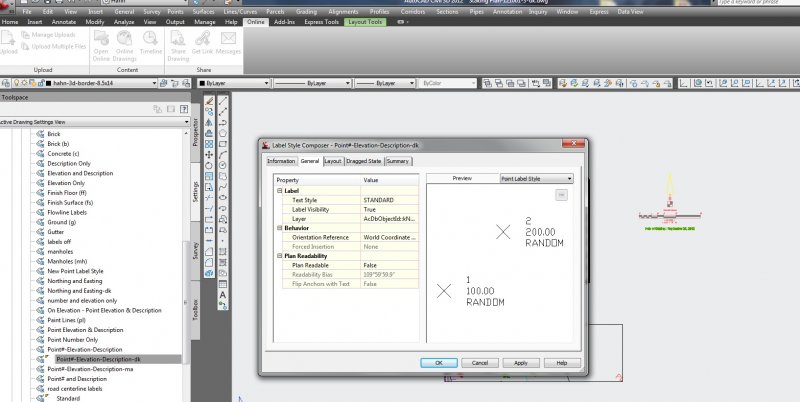
Hi All, I have a dwg that looks great in modelspace, however I created a couple paperspace layouts and then used AlignSpace to rotate to those views. The problem is that my point label style rotates the point labels based on the alignspace rotation. I looked into the point label settings and changed the orientation reference to the World Coord. Sys., but it does not help the points rotate correctly. (world reference is the goal) Any thoughts? Please see attached images.

-
:lol:hello,every1. been following this forum for 2 years.read and learned lots of problems solved here.hope my annoying problem can be solved here. :cry:whenever i make visible the "labels at vertical geometry points" and/or "ticks at vertical geometry points" in profile data band style,display tab,the label(level) will show up with 1st label outside my profile view, mostly beginning of my alignment, the last label(level) show up at end of my alignment. my profile view is set to user specified range.
-

Line type Scale for 3d polylines / blocks using XREF
Mayfly posted a topic in AutoCAD Beginners' Area
Morning all, I am very very new to autocad and trying to solve an issue I have at work regarding line types not showing up correctly. I have several .dwg files which I attach using XREF so that I can ensure I have the latest versions combined. The problem is that the line types do not show up correctly. After looking up on google I have found that this is a problem due to it being a 3d model rather than it being flat. I managed to half solve the issue by inserting each drawing into one, then exploding the whole image. Then changing the scale in the bottom right to around 1:200 to make the line types visible. My problem is this ends up being alot of work as the separate drawings can be updated daily. Is it possible to have all the drawings Xref'd in and to be able to have the scale changed to be able to read the line types? I tried to save the XREF setup as a template, then just bind all the drawings into one, explode and change the scale. But for some reason this doesnt work for me. I end up with just solid lines, rather than line types. I don't think it helps that the drawings are made up of several lines, all of different length. (This I have been told is why the scales do not appear correctly) I have been shown one method to work around this, which is to open the Xref drawings, explode them, then take each section of line and manually change each scale to the biggest that shows up. A very painful process when I might need to do it everyday!!! Any help would be appreciated. -
Hi All, I am currently working in a profile where the end point is very close to a grid line and the two labels are overlapping. I would like to remove the end point label on the grid altogether. Is there a way of doing this? Would I need to do this on the alignment first? Thanks Sooz
-
I want to put an elevation figure in along my alignment at a same intervals as the stations. Can this be added to the the station label in some way? I seem to be going around in circles with this. Any help would be gratefully received. Thanks Sooz
-
I have successfully created a whole range of particular settings for labeling my points (which are topos points with the headers of N,E,el) in the Label Style Composer and created a new style particularly for these kinds of points. Actually, i created 3 different Label Styles based on the description of the topo point) My predicament, is that clients will send me their .dwg files, and i have to import the points i collect onto there drawing which obviously don't have all the label styles I just learned to create so the points don't label correctly and i have to re-create all the styles each time?! question: How can I apply my Point Label Styles onto another .dwg? TIA!!
-
Hi all, I'm working on street profiles and I am trying to use Civil 3D's (2011) Profile Labels - Major Station Labels. I've gotten the labels to display, but they rotate in relationship to the profile line. I'd like all of the station labels to be oriented at the same angle (90°). Does anybody know how to do this, or if it is possible? Thanks.