Search the Community
Showing results for tags 'bearing'.
Found 3 results
-

Draw a Lot using Latitude and Longitude from Google Earth
Subiran posted a topic in AutoCAD Beginners' Area
Hi. I'm a beginner in CAD, I'm going to ask how to draft a lot using the coordinates(latitude and longitude) from google earth. Example: Point A. Latitude: 11 Degree 18'2.22"N Longitude: 124 Degree 57'46.89"E Please check my attachment picture. -
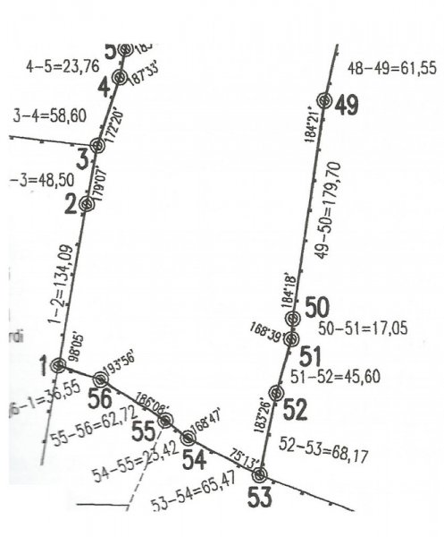
 Hi everybody, I've been reading tutorials about entering surveyor data, but still there is something I don't get it. Let's say I want to draw this scan in autocad (I already know how to enter relative xy/polar coordinates). I guess I should start the polyline at point named 1 and then enter @134.09 Segment 1-2 is visible less than 90º north, but even if I draw a visual aproximation angle for 1-2 to start de drawing, how would I then add the second segment 2-3 with the new bearing respect 1-2? How would I get a true to scan polygone? I will be gratefull of there is any explanation/example. Thanks. Paul
-
I have 2 lisp routines help draw bearing line and label them but i would have to do 2 command seperately so i am seeking someone help me combine them together. command 1 is to draw the bearing... ;Tip1741: BD.LSP Bearing/Distance lines (c)2001, Joon Hong $50 Bonus Winner (defun C:BD () (setvar "cmdecho" 0) (initget 1) (setq PT (getpoint "\nPick a starting point: ")) (initget 1 "NE NW SE SW") (setq BR (getkword "\nPick bearing (NE/NW/SE/SW): ")) (setq OPT (strcase BR)) (initget 1) (setq LEN (getreal "\nType the length: ")) (setq DEG (getstring "\nType the degree: ") minx (getstring "\nType the minute: ") SEC (getstring "\nType the second: ")) (if (= DEG "") (setq DEG "0")) (if (= minx "") (setq minx "0")) (if (= SEC "") (setq SEC "0")) (cond ((= "SW" OPT) (setvar "angbase" (cvunit 270 "degree" "radian")) (setvar "angdir" 1)) ((= "SE" OPT) (setvar "angbase" (cvunit 270 "degree" "radian")) (setvar "angdir" 0)) ((= "NW" OPT) (setvar "angbase" (cvunit 90 "degree" "radian")) (setvar "angdir" 0)) ((= "NE" OPT) (setvar "angbase" (cvunit 90 "degree" "radian")) (setvar "angdir" 1))) (command "line" PT (strcat "@" (rtos LEN) "<" DEG "d" minx "'" SEC "\"") "") (setvar "angbase" 0) (setvar "angdir" 0) (setvar "cmdecho" 1) (princ)) (princ "\nType 'BD' to draw lines with bearings") (princ) command 2 is to label the bearing line ; TIP752.LSP Distance and Bearing (c)1992, Roy Cook ;* distance and bearing label for lines (graphscr) (prompt "\nloading. . .") ;convert radians to degrees (defun rtd (R) (/ (* R 180.0) pi)) (defun C:brg2 () ;input for line notations (setq P1 (getpoint "\nfirst point: ")) (while (setq P2 (getpoint p1 "\nsecond point: ")) (setq T1 "text height: <default = " T2 ">: " T3 (getvar "textsize") );setq (terpri) (setq TH (getreal (strcat T1 (rtos T3 2 2) T2))) (if (= TH nil) (setq TH t3)) ;determine if bearings are true north, south, east, or west (defun nsew () (if (and (= (car P1) (car P2)) (< (cadr P1) (cadr P2))) (setq BNG "north") );if (if (and (< (car P1) (car P2)) (= (cadr P1) (cadr P2))) (setq BNG "east") );if (if (and (= (car P1) (car P2)) (> (cadr P1) (cadr P2))) (setq BNG "south") );if (if (and (> (car P1) (car P2)) (= (cadr P1) (cadr P2))) (setq BNG "west") );if );defun ;place text on line (setq AA (angle P1 P2) DS (distance P1 P2) P3 (polar P1 AA (/ DS 2.0)) AA1 (strcat (rtos (/ DS 12.0) 2 2) "'") );setq ;calculate bearing from coordinates and format for printing (defun bearing () (setq O (- (car P2) (car P1)) T (- (cadr P2) (cadr P1)) AZMTH (/ (* (atan (/ O T)) 180.0) pi) A (abs AZMTH) D (fix A) M (* 60 (- A D)) S (* 60 (- M (fix M))) M (fix M) );setq (if (= "60" (rtos s 2 0)) (setq M (+ 1 m))) (if (= "60" (rtos s 2 0)) (setq S 0)) (if (= "60" (rtos m 2 0)) (setq D (+ 1 d))) (if (= "60" (rtos m 2 0)) (setq M 0)) (if (< (cadr P2) (cadr P1)) (setq G "s") (setq G "n")) (if (< (car P1) (car P2)) (setq H "e") (setq H "w")) (setq BNG (strcat G "" (if (< D 10) (strcat "0" (rtos D 2 0)) (rtos D 2 0)) "%%d" (if (< M 10) (strcat "0" (rtos M 2 0)) (rtos M 2 0)) "'" (if (< S 10) (strcat "0" (rtos S 2 0)) (rtos S 2 0)) "''" "" H)) );setq ;bearing and distance on line (if (or (= 0 (- (car P1) (car P2))) (= 0 (- (cadr P1) (cadr P2)))) (nsew) (bearing)) (command "text" "m" (polar P3 (rem (+ AA (/ pi 2)) (* pi 2.0)) TH) TH (rtd AA) AA1) (if (or (> (car P1) (car P2)) (= (rtd AA) 270)) (command "rotate" "last" "" P3 180.0) );if (command "text" "m" (polar P3 (rem (+ AA (* pi 1.5)) (* pi 2.0)) TH) TH (rtd AA) BNG) (if (or (> (car P1) (car P2)) (= BNG "south")) (command "rotate" "last" "" P3 180.0) );if (command "line" P1 P2 "") (setq P1 P2) ) (princ);end program cleanly );defun thank you in advance