Search the Community
Showing results for tags 'automation'.
Found 16 results
-
Hello, I'm trying to write a code that changes the dimension style of all dimensions in layer Dimension(ISO). I need the code to change it to variable "DimStyleOverrider" and this variable must be dependant on another variable. When OldFactor = 10 I need "DimStyleOverrider" to be "Change10" and when OldFactor = 5 I need it to be "Change5". You can assume these styles already exist in the file. I hope someone can help me.
-

LISP for Selection of alternate lines from the selection set of lines like 1st, 3rd, 5th, .....etc lines in autocad.
Pranesh Rathinam posted a topic in AutoLISP, Visual LISP & DCL
Hello guys, I am new to this forum. I need LISP for Selection of alternate lines from the selection set of lines like 1st, 3rd, 5th, .....etc lines in Autocad. I am attaching the file with my requirement. Alternate Selection of lines.dwg Please help me out with an possible lisp solution. Also, Is there a Autocad Plugin to do this? If so Please share the link Thanks in advance, Pranesh Rathinam -

How to use Wire Copy (AECOPYWIRENO / WD_COPY_WN) in LISP
NicholasCAD posted a topic in AutoLISP, Visual LISP & DCL
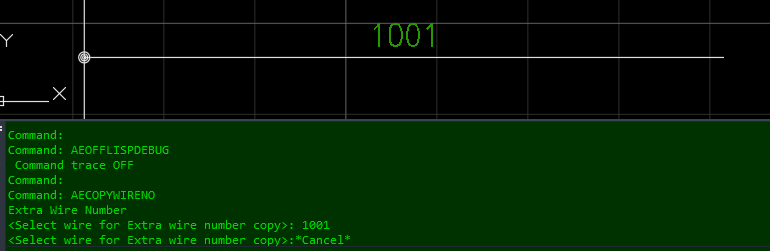
(Hopefully this Question has not been asked. The Search gave no Results.) For Context: I have created a Program that generates a complex Component (Block, Wiring, Text) onto a Sheet. The Program uses .LSP and .DCL for ease of Use for our Operators. The Prompt has Options to configure the Component to any Options we need. Inquiry: I need to update the Program to include Wire Numbers and Wire Number Copies. (I will be trying to use "WD_PUTWNXY" Command for New Wire Networks, although I have yet to do so.) For Wire Number Copies, I was hoping to use either the "AECOPYWIRENO" or "WD_COPY_WN" Commands. The Problem with these Commands is that they do not allow for Coordinate Placement. When running either Command, the Command Line is requesting to select a Wire as an Entity. What I would like, is an example of a LISP that completes this Task using a Coordinate System to select and place the Wire Number Copies. Any Advice would be much appreciated!
-

Need help editing a LISP command I am using for better usability
eb14 posted a topic in AutoLISP, Visual LISP & DCL
Hey guys, this is my first post on this forum so thanks in advance for any help. Currently I am using Lee Macs "Field to attribute" lisp command to get the length of a line (a steel beam in this case) and insert the field into a block to get an item count. Currently I've modified the LISP command to format the length from feet-inches into a single number to represent a 1' spacing of our product. What I want to do is either take that field value (the length of the beam) and and 1'-0" to it, or take the formatted value and add 1 to it. The reason is when we draw our beams we like to shorten the lines by 6" on each side so we know what beams are separate members and which are continuous. This causes the field value to be 1'-0" less than it should be. Any help on this would be appreciated. -

EXPLODE ALL BLOCKS EXCEPT IN THIS SPECIFIC LAYER
williamferenal posted a topic in AutoLISP, Visual LISP & DCL
Hi. I am a newbie with Lisps. But was just wondering if there is an existing lisp out there to explode all blocks (both model space and paper space) except for blocks in this layer "A3_TT"? I am trying to look for a routine cause I need to apply it to almost thousands of drawings. Any help would be much appreciated. Best regards, William -

automation How to create random but "inline" stipple line or hatch pattern
pseudoclay posted a topic in AutoCAD 2D Drafting, Object Properties & Interface
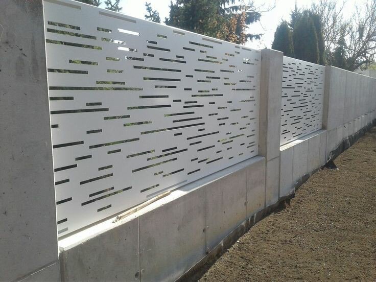
Good Day AllI've turned to forum advice and I really hope someone can help me.I have to create 13 wall panels that will be laser cut. The panel drawings were done in Inventor and I'm editing the flat pattern in AutoCAD. If you look at the attached images of one of these panels you will get the idea, each panel cut-out "pattern" must be randomly generated and I was hoping someone could give me some advice as doing this manually, by hand, is insane and after all we work on machines and machines can automate right!? I am also attaching a flat pattern of one of the panels (they all have different height and width dimensions too). Just as a side note I did try a scatter script but it doesn't give the appropriate result because if you look closely you will see the dashes are inline but randomly knocked out. I was thinking maybe a random dashed line script or procedure that can then be exploded to rectangular shapes for DXF export or a custom random hatch but I don't know how to do either. Hope I'm making sense. Thank you in advance.
-
HI, I need to create a Lisp to do the following in a series of drawings within a folder and then save as a new file. Superflatten entire drawing. Audit and fix errors. overkill entire drawing Convert all. Purge all. Remove Hatching. Remove DIms. Create boundary box from most southern and most western extremities of building. move boundary box and content from basepoint to be 2000,2000 from 0,0. Id like to type "deepclean" as command in future, I have over 1000 drawings to run this on so ideally id like to find a routine which will automatically do this to all files within a folder, without the need to manually open each one?
-

Pack of plugins to automize design engineering processes in AutoCAD
AADB Software posted a topic in .NET, ObjectARX & VBA
Hello. I would like to show you my pack of plugins to automize design engineering processes in AutoCAD. My professional field is Audio/Video/Radio/TV etc complexes. I need your professional feedback. Is it useful or not? Is it comfortable to work?Is it make your work easier? Please, visit aadbsoftware.com. Also there is Youtube Channel where I put all videos with working plugins. P.S I forgot to mentioned that only for two plugins are paid because of databases. Other, such as DrawRack and FillRack, are free to use forever. If you download and install DEMO you will have them for free. -
Hello All, This is my first post on CADTutor forum. This is a pretty extensive request, however I am looking to essentially do this exact routine: https://www.youtube.com/watch?v=FLOif87iLMw This automated process of creating the stepped boundaries to angled polylines based on the size of a panel, as well as automatically drawing panels into the drawn boundaries, etc, is everything that I need. Creating profile views, cross sections, etc. The question is, are there any AutoCAD commands that would expediate this programming or do I need to brute force this and essentially create a lisp routine from scratch? The more basic the steps, the easier I would be able to understand because I am relatively new to AutoCAD in general. In general where do I start? Thank you in advance for any help!
-
Check out this new Engineering & CAD automation service. AutoEngr.com. Our services include CAD API programming and parametric modeling services for zero up-front costs. We create custom automation to match you needs, then run it whenever you need to complete the task. It's a hassle free low cost solution to automation. Request a custom service or use an existing off-the-shelf service today!
-
Hello everyone, my name is Bruno and this is my first post here!! Is important to say that I work with cad since 2014. I'm good in 2-D , and I have a little of experience in 3-D drawning. I'm sorry, but I've never used a Lisp. This is what is happening: I was teaching numerical integration to my brother using autocad. I made a drawning and divide it into ten equally spaced segments, as showed below. I used " ID " to get the length of each chord, so I could paste into a excel sheet and calculate the area. My doubt is: Is there any way to get the ID of multiple lines without click one by one? This is fine when you divide a drawning into 100 , 1000 or 1 000 000 of spaces. Cheers!!
-
Hi, was wondering if there was any routine which would automate dimensions in an architectural plan. This is present in refit, and we could have it in Autocad where we could draw a line through a floor plan and "stretch" the dimensions of all the intersecting lines to a convenient point. Thanks
-

Automation/Macros in drawings, templates, and part making
andar424 posted a topic in Autodesk Inventor
Hey guys, Just curious and looking for suggestions, but like the title says, what kind of automation or macros do you guys like to run in your Inventor? For example, we tend to have to send pdf's of part prints instead of actual Inventor or CAD formats to manufacturers for release or what not. So, in the drawing template there is a rule that runs and creates (if one doesn't exist) or resaves (if it does exist) a pdf file every time you save. And as always, I like to hit save a bunch so I lose as little info as possible if my computer crashes or Inventor does. As long as you have the option to not preview the file after it is exported/saved, it doesn't slow your saving down too much. Other than that really, I don't have much else. I've thought of a few I might like to add or research how to do myself through macros and VBA, but can't seem to find the down time to work on it much. Any other little tools/add-ons you like to run with your Inventor? -

Automatically generate a Layout Tab
dblclkmatt posted a topic in AutoCAD Drawing Management & Output
Hey guys, This seems like an impossible maneuver, but I'd kick myself if I didn't ask the question. What'd I'd like to do: Essentially draw a selection box/window around an object in model space, and it is auto-magically captured inside of a viewport on a brand new Layout tab (duplicating the layout settings of an already existing "master" tab). I'm so used to using the "Print Window" feature, it seems liked it'd be possible to snapshot objects in this manner in a more permanent fashion, making plotting quicker and easier. Especially if I need to do multiple prints. Thoughts? Suggestions? Alternatives? Thanks guys! -
Hello Everyone! I am using vanilla AutoCad (R14-2012) and was wondering what the best solution would be for this problem (other than manually drawing each outline which I currently do!) I am looking to draw polylines along each point creating a polyline outline (perimeter) around the selected points. This in itself is quite difficult to do well(haven't found a great method yet) but there are multiple groups of points that I would like polylines around without selecting each individual group of points (in an ideal world). I realize that getting something 100% right is impossible and some manual editing (maybe a lot!) will be required. Attached is a sample of the points I usually have to work with. Test 05 2013.dwg I have done a bit of research and found some close solutions which I will post below. 1. Draw the polyline by point ID (can't remember author) (vl-load-com) ;;; to make a 3d polyline******************************************* (defun c:pol (/ adoc spc ss cnt plst 3dline) (setq adoc(vla-get-activedocument(vlax-get-acad-object))) (setq spc(vlax-get adoc (if (equal (getvar "cvport") 1) 'PaperSpace 'ModelSpace );_if ) );_setq (setq ss (ssget '((0 . "POINT"))));_select only point objects (if ss (progn (setq cnt 0);_loop counter (setq plst '());_empty list (while (< cnt (sslength ss)) (setq plst (cons(cdr(assoc 10(entget (ssname ss cnt))))plst));_make point list (setq cnt (1+ cnt));_incerase counter );_while (setq 3dline (vla-add3dpoly ;_make 3d polyline spc (vlax-safearray-fill (vlax-make-safearray vlax-vbDouble (cons 0 (1- (length (apply 'append plst))))) (apply 'append plst))) );_setq add 3dpoly );_progn );_if (princ) );_defun ;;; to make a 3d spline****************************************** (defun c:spl (/ adoc spc ss cnt plst 3dline stpt ept) (setq adoc(vla-get-activedocument(vlax-get-acad-object))) (setq spc(vlax-get adoc (if (equal (getvar "cvport") 1) 'PaperSpace 'ModelSpace );_if ) );_setq (setq ss (ssget '((0 . "POINT")))) (if ss (progn (setq cnt 0);_loop counter (setq plst '());_empty list (while (< cnt (sslength ss)) (setq plst (cons(cdr(assoc 10(entget (ssname ss cnt))))plst)) (setq cnt (1+ cnt));_incerase counter );_while (setq stpt (vlax-3d-point '(0.0 0.0 0.0)));_start pt for spline (setq ept (vlax-3d-point '(0.0 0.0 0.0)));_end pt for spline (setq cline (vla-addspline spc (vlax-safearray-fill (vlax-make-safearray vlax-vbDouble (cons 0 (1- (length (apply 'append plst))))) (apply 'append plst)) stpt ept ) );_setq add 3d spline );_progn );_if (princ) );_defun 2. Convex Hull (Lee Mac ftw) ;; Convex Hull - Lee Mac ;; Implements the Graham Scan Algorithm to return the ;; Convex Hull of a list of points. (defun LM:ConvexHull ( lst / hul p0 ) (cond ( (< (length lst) 4) lst ) ( t (setq p0 (car lst)) (foreach p1 (cdr lst) (if (or (< (cadr p1) (cadr p0)) (and (equal (cadr p1) (cadr p0) 1e- (< (car p1) (car p0))) ) (setq p0 p1) ) ) (setq lst (vl-sort lst (function (lambda ( a b / c d ) (if (equal (setq c (angle p0 a)) (setq d (angle p0 b)) 1e- (< (distance p0 a) (distance p0 b)) (< c d) ) ) ) ) ) (setq hul (list (caddr lst) (cadr lst) (car lst))) (foreach pt (cdddr lst) (setq hul (cons pt hul)) (while (and (caddr hul) (LM:Clockwise-p (caddr hul) (cadr hul) pt)) (setq hul (cons pt (cddr hul))) ) ) hul ) ) ) ;; Clockwise-p - Lee Mac ;; Returns T if p1,p2,p3 are clockwise oriented or collinear (defun LM:Clockwise-p ( p1 p2 p3 ) (< (- (* (- (car p2) (car p1)) (- (cadr p3) (cadr p1))) (* (- (cadr p2) (cadr p1)) (- (car p3) (car p1))) ) 1e-8 ) ) (defun c:test1 ( / i l s ) (if (setq s (ssget '((0 . "POINT")))) (progn (repeat (setq i (sslength s)) (setq l (cons (cdr (assoc 10 (entget (ssname s (setq i (1- i)))))) l)) ) (setq l (LM:ConvexHull l)) (entmakex (append (list '(0 . "LWPOLYLINE") '(100 . "AcDbEntity") '(100 . "AcDbPolyline") (cons 90 (length l)) '(70 . 1) ) (mapcar '(lambda ( x ) (cons 10 x)) l) ) ) ) ) (princ) ) 3. Create surfaces out of points using triangulation and limit the length of triangle then use bounding box to create polyline(hard to do in vanilla AutoCad). 4. Neat solution shown by Tyke (which I don't have the code for) 5. Possibly use multiple Bpoly commands, somehow getting the Bpoly command to recongnize points??? 6. Outsource? Anywho, if you guys have any ideas as to (too?) other methods/possible solutions/software programs/ANYTHING that could be of help that would be awesome! Thanks again for reading, Kablamtron
-
Hi all ... Not new to v/lisp, but new to this great forum. I'm looking to automate title block revision, pdf generation and transmittals via lisp (which will probably be later converted to VB). My question is: Is it possible to create pdf's via script that will assign filenames [which I will extract from the drawings] ? from what I have managed to ascertain this is achievable. 1) by a 3rd party pdf application (which I'm not against, but I would just prefer an all-in-one custom solution to save on portability/deployment issues) 2) by editing a registry entry (not keen on this, hopefully avoidable) to be passed to the pdf driver. If someone suggests using publisher, I have limitations using it - particularly in regard to assigning the file name exactly as I want it, and without a dialog. Have had no luck using the DWG to PDF.pc3 supplied by AutoDesk either.