Search the Community
Showing results for tags 'surfaces'.
Found 8 results
-

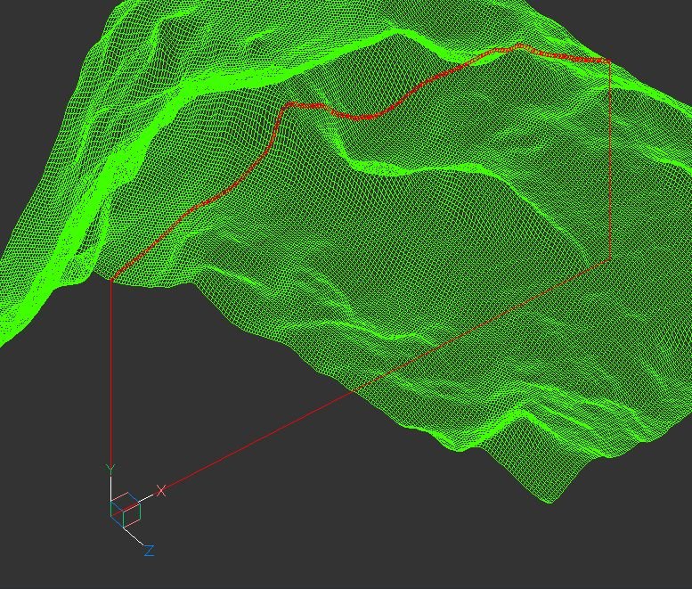
terrain Cross section of the 3D terrain
Andrej Skvarca posted a topic in AutoCAD 3D Modelling & Rendering
Hi guys, I've created an AutoLisp app which creates a cross section of the 3D terrain grid. The terrain can consists of raw AutoCAD entities: MESH / POLYFACE MESH / POLYGON MESH (one or more, even combined). As an author, I will be grateful for any comment, especially suggestions for improvements and developments. Andrej Skvarca TERRAIN_CROSS_SECTION.fas
-
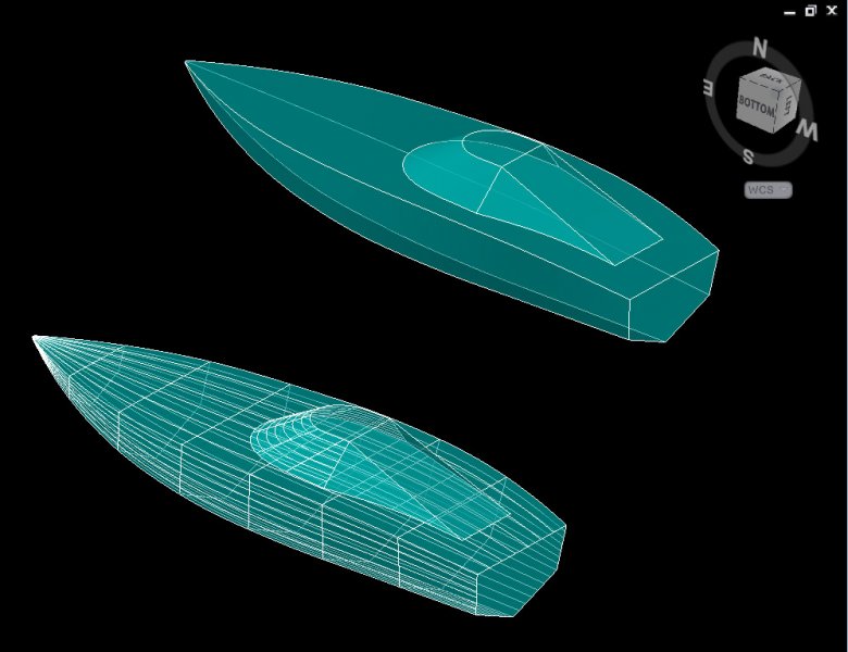
Hi! Is anyone who could help me to unfold surfaces from a drawing that I have made. I want to make a RC boat. Thank you in advance!
-
Hello I am trying to understand the logic behind the display of 2D solid surfaces in autocad 2000. if you have a same area covered by different 2d surfaces in different layers with different colour which layer or surface hides what surface or layer. Does it depend on the order they are created, does it depend on the colour , is there a method to make one layer cover another. All layers must be on. And what about lines that cross these surfaces , some times they show and some times they don't. Is there a logic behind this? Thanks in advance for your answers
-

How do I show machined finishes on selected surfaces in 3D models?
Vagulus posted a topic in Autodesk Inventor
That's it! How do I? I can't find it in Autodesk Help or in my textbooks. Google and YouTube were similarly unhelpful. Still, most models I see in books have finish representation. How is it done? Thanks -
 Hi, I have an urgent problem that I'd be really grateful for some help with. I've built a model in AutoCAD 2013 - which is the software Ihave available - and I need to export it to SketchUp in order to transfer itfurther to yet another program. But I get stuck on just getting it saved in an old enough AutoCAD-version. It all looks fine in AutoCAD 2013, but when I try saving as a 2007-file and then import it in SketchUp almost everything is lost. The model consists of surfaces, and a few that originally were made in AutoCAD 2000 remain, but all the others are considered incompatible and are simply disregarded. On forums concerning SketchUp it is stated that surfaces based on splines are not supported and I guess all my swept surfaces are then not accepted, but how canI convert my model - or the surfaces - to something edible for SketchUp or even the old AutoCAD 2000-version I still have on my old computer? Exactly the same thing happens there, the surfaces that show up in 2000 are the same that show up in SketchUp. I have tried converting to 2007 and 2000, and just save as 2007 and 2000 drawings, I've broken the connection between the lines used to create the surfaces and the surfaces themselves and nothing seem to help. Its a rather large model that has taken me weeks to build and I should have been finished weeks ago, so I'm a bit desperate and I definitely don't want to have to redo the entire project....
 -

turn off one of two overlapping surfaces
tomhoban posted a topic in AutoCAD 3D Modelling & Rendering
Hello all I am using 3dc 2014. I have two surfaces which overlap (existing surface and proposed surface). I would like to analyse each surface to check for errors, e.g.look at the contours, slopes, triangles etc. I want to do this one surface at a time but can not see how to turn one surface off. Turning on or off the various options (contours, slope, etc) in "edit surface style>display, will apply the changes to both surfaces. I have tried locking one surface but this does not work. Any help would be appreciated. Thanks Tom -

3D Meshed surface from a extruded spline irregular shape.
Skyhigh posted a topic in AutoCAD 3D Modelling & Rendering
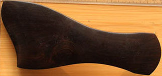
Hello All, I am trying to create a 3D meshed surface from an irregular shaped solid I created using firstly a SPLINE, FILLET, PEDIT, and EXTRUDE. I have a solid in the basic shape now, but I am trying to create a meshed top and bottom (x, y, z,) to change the contours of those surfaces. Can anyone help in this regard? I have looked at 3DMesh but it asks for (n,M,) coordinates like it is a regular shaped surface (square, rectangle) where one can calculate the required even spacing needed. My goal is to create in CAD something like a fine art carved piece of wood, with irregular shaping and no straight planes or surfaces. I have included a basic picture in JPEG format for your review. This is the item from which I am trying in ACAD 2010 to construct into a usable adjustable form so I may parametric for my needs. Thank you, Sky....
-
Hi, This is my first post. I hope someone can help me. I have been given a file initially made in Solidworks that consists of the front end of a car made with surfaces. I have the Solidworks file as well as a IGES export and a STEP file version. The ultimate goal is to slice this model into 1-1/2 " slices so that it can be exported to BobCAD/CAM and milled. I have tried creating a plane off to the side of the model and drawing a pair of rectangles then extruding a cut through the model. Inventor does not allow me to even select the cut feature (I think this is called 'subtract', sorry I am not in front of my Inventor PC at the moment.) My question is, how can I take a 3D model made entirely of surfaces, and make a set of cuts so that I am left with only a slice of the model, which I can then export as an IGES or STEP file to be milled? I am fairly well versed in Inventor, but only making solid parts, not working much with surfaces. Thanks.