Search the Community
Showing results for tags 'points'.
-
Version 1.0.0
931 downloads
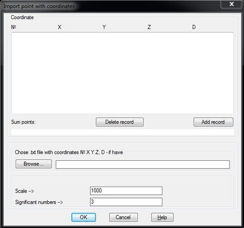
This lisp import point from txt file with № X Y and if have (H and D). In the lisp can add records and delete records. command: PointIn -

Select points from point cloud and make aproximate planar surface
ibach posted a topic in AutoLISP, Visual LISP & DCL
I'd really love to be able to select points from a point cloud and create a planar surface from selected coordinates. Further on I'd like to be able to select the points to be used as polygon boundary of that surface. So... Pick a lot of points from the point cloud, select points for boundary vertices, calculate the middle value of x, y, z for all selected points, not taking the boundary vertices into the account for the direction of the plane but projecting them onto the calculated plane as a boundary vertices only, create the planar shape in the calculated plane. -
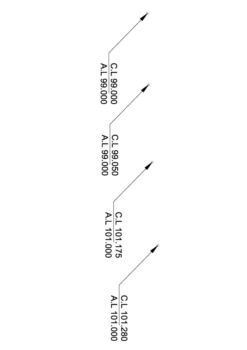
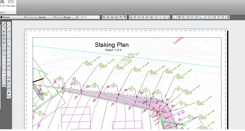
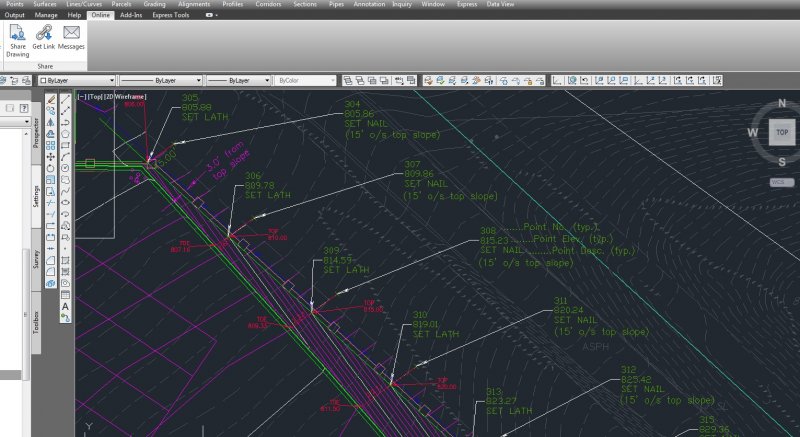
 Hi Everyone, i,m looking for LISP Program that will display Z value of 3D points as A.L=0.000 (Asphalt Level) and prompt for height between Asphalt level and top of curbstone levels because its varies and display as C.L=0.000 (Top of Curbstone level) on screen. i have a lot of data to process. for format please see the attached image.
-
Could anyone help me please? I currently use CAD 2016 for setting out groundworks on site. I have taught myself with the help of online videos etc and am making slow progress. I am stuck on how to import and export points to and from my drawings and total station control unit. I will try to explain the typical process that I'm trying to understand. From an existing .dwg I want to add and select multiple points and export them to my control unit. I can currently do this but cad labels the points automatically and I would like to control how they are numbered. I'm certain it's easy but I can't seem to find any video that answers my problem. Thanks in advance for any advice or hints.
-
Greetings, everyone ! May I introduce myself a bit : I'm Gauvain Boiché, I'm currently studying Video Games in Belgium. I am now in an internship in a small company. We usually use 3DS Max 2017 for modelling, but now I'm struggling on a problem, as I have to use AutoCAD 2018. And I am totally lost. To be honest, I'm not intended to use AutoCAD after that, so this is really a one-shot of despair It is for a very-very small problem. We have to sell some of my products for a bigger company, but they are asking it in DWG. And I have to convert my FBXes with Material IDs to DWG, with the good colors, to Revit. We found a "good" tutorial about it, here : Long story short : I don't speak Spanish ( or Portugese ) and the shower is not telling anything I can understand. Probably he is using a shortcut I can't translate. He lost me at 5:10 in the video. I managed to re-organize my workspace, which looks like this : http://i.imgur.com/IMhfktT.png Now, I'm really struggling, and I have basically no time to just learn about AutoCAD, and not even Revit then. So, my question is : - How did he select point on the object, bypassing in the process the unwanted ones ? And, to be shorter, if you know any way to just export an object from 3DS Max with material IDs and good color directly to Revit, I would be eternally grateful Thank you in advance for your time !
-
I was given a document (not a point file) of lat and longs, is there a way to create a points using LAT LONG instead of northing and eastings? I can't seem to find anything on this. I created a new .txt file using the lat and long but it only seems to recognize northing easting. Which in turn brings the points in close to 0,0 and not the coordinates it needs to be in. Thanks! I am currently using Civil3D 2015
-

creating layer with code for each point
john-g posted a topic in AutoCAD Drawing Management & Output
hello guys !! im trying to import Points from Leica device and i want to creat a layer for each Point depending on its code ,if anyone have ideas how to do it i will be thanksfull best regards !!! -
Good afternoon, I need to delete all points between 0 cm and 15 cm spacing. If I can use an object as a base or a layer it will be even better. With OVERKILL command it deletes randomly objects that only are overlapping. Is there any lisp that can make this?
-

3d points or 3d polyline along the given path
MAINISL2 posted a topic in AutoLISP, Visual LISP & DCL
Hi there I am looking for some kind of lisp to import points or 3d polyline along with a reference line. I am attaching reference files for study. thanks Bridge Plan.dwg Profile Data.csv -
Hi everybody, this is my first post. I need a Lisp to generate a polyline from existing points. The polyline should be created from all the points at the edge of the cloud of points generated by a 3d scanner. The points are in 3 dimensions, but they could be flatted to zero. The polyline can be close or open: it does not matter. Any idea? Thank you folks in advance. dave:acad:
-

Linking points with a 3dpoly line automatically
toxicsquall posted a topic in AutoLISP, Visual LISP & DCL
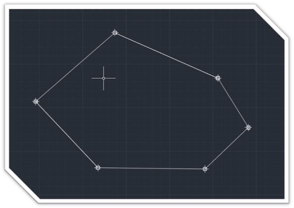
I’d like to know if you have one LSP that links points with some 3D POLY LINE between then. Something like an outline, just like this: It is link points given by coordinates. I upload from a device the coordinates and import points to AutoCAD, but I have to link them like the picture. It doesn't have an order, but the 3d lines are only the outside. It will be good if I can select them to link or even link by layer, because I work with tunnels and each point represents the edge of it.
-
It would seem that the Place Component function can no longer place a Pivot in this version. How can it be done?
-
Hey guys, I'm trying to make a lisp where the user would pick a point in the model and the lisp would create a multileader in paperspace with the coordinates pulled from the model. Here's the code I got so far: (defun c:test (/ WorkingPoint Easting Northing Point) (command "_.mspace" );;end command (setq WorkingPoint (getpoint "\nWhere is Working Point?: ")) (setq Northing (cadr WorkingPoint));;set "y" value of WorkingPoint to Northing (setq Easting (car WorkingPoint));;set "x" value of WorkingPoint to Easting (command "_.point" WorkingPoint );;end command (setq point (entlast));;set the workingpoint to point (command "_.chspace" point "" "" );;end command (setq pspaceworkingpoint (entget point)) (setq mleaderinspt (list (car pspaceworkingpoint)(cadr pspaceworkingpoint))) (princ mleadinspt) );;end defun Whenever I run this, for the "mleaderinspt" variable I get nilnil What I want to do is create the multileader insert point where the user picked the original working point but I'm having a hard time translating that to the paperspace. Please note I haven't added error checking yet as this is still in the developmental phase/proof of concept. Any and all help is appreciated. Thanks! EDIT: Think I figured it out, I'll update this thread if it works.
-
I'm new at the forum and have to get a drawing out the door. I am a surveyor. Here's what I have, It just started. When I go to import points, then click the folder for the destination of the .txt or ascii file it gives me a fatal error. Never had this happen. I did open up another drawing someone set me that was pretty old but I did have any problems with it. Also, it remember the last destination folder and I tried to import it and it had no problem. So I put that folder on the jump drive to see if it would give me a fatal error and didn't, just couldn't find it, but when I click the folder icon(destination folder for .txt) I get a fatal error every time. Any Ideas???? Thank you.
-
I look for a routine that will resolve the following task: 1 - I select a group of text entities (in this case numbers) 2 - Then I draw a point near the position of one 3 - Finally, the routine must be able to replicate the point in the other text strings, maintaining the same close relationship defined in step 2 Attached a drawing to better understand Tanks for help! cadtutor_test_points.dwg
-
Hello all, I have received a redesign from a sub that is a bit problematic. I will explain it as best I can. The plan has a main road alignment. I have received a redesigned pipe design. I have the pipe alignment, no problem there. It runs along the road alignment, not parallel, and crosses from one side of the road alignment to the other in several places. The issue is with the pipe profile. The sub created, reused, my road alignment profile and drew their pipe profile on it. They labeled station and elevations on their profile. The stationing is based on the road alignment and elevations are for their pipe profile. Since their profile is drawn on the road profile it is 'stretched' in some areas and greatly foreshortened in others. Does someone know of a slick way for me to project the pipe profile elevations to the pipe alignment so I can generate a feature line? Civil only wants to place the points on the road alignment. I'd just do it manually but it's about 3,500' and a lot of points. Thanks in advance for any help or ideas. Phil Additional info There are only a very few pipe profile elevations that match the pipe alignment geometry points.
-
I have tried several combination and gone thru about a 100 posts but I can't figure out what I am doing wrong. I am filtering thru objects and pulling out a 3D coordinate from the database. Then I am turning that into a 3 point list (x y z). Then I want to create a list of those points and add to them to the existing list as the program filters thru the remaining objects from the selection set. (progn (setq unitpoint_orig (vl-string-right-trim ";" (substr (vlax-get entvla 'points) 12))) (if (and(or (= Z_pref "Y")(= Z_pref "y"))(/= Z_height nil)) (progn (setq unitpoint_mod (comma_pull unitpoint_orig "REAL_NUM")) (setq unitpoint (list (car unitpoint_mod) (cadr unitpoint_mod) (caddr Z_height))) ) (setq unitpoint (comma_pull unitpoint_orig "REAL_NUM")) ) (setq unitpoint_lst (append unitpoint_lst 'unitpoint)) ;(command "insert" pl_block unitpoint "1" "1" "0") ) Current Result: (105.13 3165.22 0.0 105.13 3194.65 0.0 105.13 3142.5 0.0) Desired Result: ((105.13 3165.22 0.0)(105.13 3194.65 0.0)(105.13 3142.5 0.0)) Once I get this part working, I am then planning on filtering for duplicates using Lee Mac's subroutines. Then inserting based off those points.
-
Is there a simple way to export points from the three different axis in a .dxf file for three different views (top, side and front) in autocad 2012? I need to export the points in to excel to run a macro in CATIA to create the surface of an aircraft. I got the .dxf file from the boeing website http://www.boeing.com/boeing/commercial/airports/3_view.page it is a 777-200 Thanks!
-

Making points selectable
Baber62 posted a topic in AutoCAD 2D Drafting, Object Properties & Interface
Hi Folks, I have got points from a GIS software into AutoCAD, the problem is that I am unable to draw a polyline between the points to get a distance between the points. Does someone have a lisp routine which can convert the points to make them selectable. I have attached the drawing I am working on for those of you who want to have a go at this one. Thanks in advance. Gullies.dwg -
Hello Everyone! I am using vanilla AutoCad (R14-2012) and was wondering what the best solution would be for this problem (other than manually drawing each outline which I currently do!) I am looking to draw polylines along each point creating a polyline outline (perimeter) around the selected points. This in itself is quite difficult to do well(haven't found a great method yet) but there are multiple groups of points that I would like polylines around without selecting each individual group of points (in an ideal world). I realize that getting something 100% right is impossible and some manual editing (maybe a lot!) will be required. Attached is a sample of the points I usually have to work with. Test 05 2013.dwg I have done a bit of research and found some close solutions which I will post below. 1. Draw the polyline by point ID (can't remember author) (vl-load-com) ;;; to make a 3d polyline******************************************* (defun c:pol (/ adoc spc ss cnt plst 3dline) (setq adoc(vla-get-activedocument(vlax-get-acad-object))) (setq spc(vlax-get adoc (if (equal (getvar "cvport") 1) 'PaperSpace 'ModelSpace );_if ) );_setq (setq ss (ssget '((0 . "POINT"))));_select only point objects (if ss (progn (setq cnt 0);_loop counter (setq plst '());_empty list (while (< cnt (sslength ss)) (setq plst (cons(cdr(assoc 10(entget (ssname ss cnt))))plst));_make point list (setq cnt (1+ cnt));_incerase counter );_while (setq 3dline (vla-add3dpoly ;_make 3d polyline spc (vlax-safearray-fill (vlax-make-safearray vlax-vbDouble (cons 0 (1- (length (apply 'append plst))))) (apply 'append plst))) );_setq add 3dpoly );_progn );_if (princ) );_defun ;;; to make a 3d spline****************************************** (defun c:spl (/ adoc spc ss cnt plst 3dline stpt ept) (setq adoc(vla-get-activedocument(vlax-get-acad-object))) (setq spc(vlax-get adoc (if (equal (getvar "cvport") 1) 'PaperSpace 'ModelSpace );_if ) );_setq (setq ss (ssget '((0 . "POINT")))) (if ss (progn (setq cnt 0);_loop counter (setq plst '());_empty list (while (< cnt (sslength ss)) (setq plst (cons(cdr(assoc 10(entget (ssname ss cnt))))plst)) (setq cnt (1+ cnt));_incerase counter );_while (setq stpt (vlax-3d-point '(0.0 0.0 0.0)));_start pt for spline (setq ept (vlax-3d-point '(0.0 0.0 0.0)));_end pt for spline (setq cline (vla-addspline spc (vlax-safearray-fill (vlax-make-safearray vlax-vbDouble (cons 0 (1- (length (apply 'append plst))))) (apply 'append plst)) stpt ept ) );_setq add 3d spline );_progn );_if (princ) );_defun 2. Convex Hull (Lee Mac ftw) ;; Convex Hull - Lee Mac ;; Implements the Graham Scan Algorithm to return the ;; Convex Hull of a list of points. (defun LM:ConvexHull ( lst / hul p0 ) (cond ( (< (length lst) 4) lst ) ( t (setq p0 (car lst)) (foreach p1 (cdr lst) (if (or (< (cadr p1) (cadr p0)) (and (equal (cadr p1) (cadr p0) 1e- (< (car p1) (car p0))) ) (setq p0 p1) ) ) (setq lst (vl-sort lst (function (lambda ( a b / c d ) (if (equal (setq c (angle p0 a)) (setq d (angle p0 b)) 1e- (< (distance p0 a) (distance p0 b)) (< c d) ) ) ) ) ) (setq hul (list (caddr lst) (cadr lst) (car lst))) (foreach pt (cdddr lst) (setq hul (cons pt hul)) (while (and (caddr hul) (LM:Clockwise-p (caddr hul) (cadr hul) pt)) (setq hul (cons pt (cddr hul))) ) ) hul ) ) ) ;; Clockwise-p - Lee Mac ;; Returns T if p1,p2,p3 are clockwise oriented or collinear (defun LM:Clockwise-p ( p1 p2 p3 ) (< (- (* (- (car p2) (car p1)) (- (cadr p3) (cadr p1))) (* (- (cadr p2) (cadr p1)) (- (car p3) (car p1))) ) 1e-8 ) ) (defun c:test1 ( / i l s ) (if (setq s (ssget '((0 . "POINT")))) (progn (repeat (setq i (sslength s)) (setq l (cons (cdr (assoc 10 (entget (ssname s (setq i (1- i)))))) l)) ) (setq l (LM:ConvexHull l)) (entmakex (append (list '(0 . "LWPOLYLINE") '(100 . "AcDbEntity") '(100 . "AcDbPolyline") (cons 90 (length l)) '(70 . 1) ) (mapcar '(lambda ( x ) (cons 10 x)) l) ) ) ) ) (princ) ) 3. Create surfaces out of points using triangulation and limit the length of triangle then use bounding box to create polyline(hard to do in vanilla AutoCad). 4. Neat solution shown by Tyke (which I don't have the code for) 5. Possibly use multiple Bpoly commands, somehow getting the Bpoly command to recongnize points??? 6. Outsource? Anywho, if you guys have any ideas as to (too?) other methods/possible solutions/software programs/ANYTHING that could be of help that would be awesome! Thanks again for reading, Kablamtron
-

Adding points at multiple intersections
SAFeSTeR posted a topic in AutoCAD 2D Drafting, Object Properties & Interface
Hi, I need to know if there is a simpler way of adding points to a string 3D polylines which are intersected with multiple 3D faces. Up until now I've been doing it manually which is taking ages, not to mention quite tedious. I've looked on Lee Mac's site for a LISP, but it's a bit hit and miss searching for a answer, in fact I've only missed! Any help appreciated. -
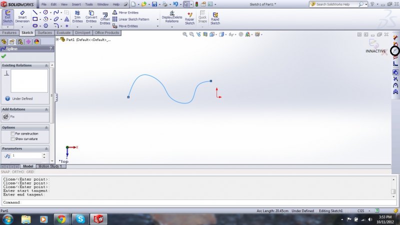
Hi, I'm using SolidWorks 2012 and when I'm trying to sketch the basic spline, the Spline Points feature is innactive. So, basically, I cannot draw it in the way I need to. Screenshot is attached. How to make it active ? Any ideas ?
-
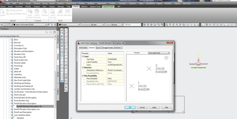
Hi All, I have a dwg that looks great in modelspace, however I created a couple paperspace layouts and then used AlignSpace to rotate to those views. The problem is that my point label style rotates the point labels based on the alignspace rotation. I looked into the point label settings and changed the orientation reference to the World Coord. Sys., but it does not help the points rotate correctly. (world reference is the goal) Any thoughts? Please see attached images.
-

Survey Points, symbol scales, and xref's...
Supermanny73 posted a topic in AutoCAD Drawing Management & Output
In Civil 3D 2012 I set up a base drawing where I insert field survey points. The points come in with appropriate feature code symbols. These symbols (power poles, hydrants, valves, manholes, etc.) will scale up or down relative to the drawing scale. If my base drawing is set at 1"=100' (thereby making my symbology 100 times bigger) and i reference it into a sheet drawing that is set up to 1"=20', how can I appropriately scale the symbology to be the right size (1"=20') in my sheet without having to change the scale in my base drawing? Is there a way to make the point symbols annotative according to the drawing it is refenced similar to pipe networks? -
How do I move point from one file to another in Civil 3d? Copy/Paste won't work. I need to import them to the second drawing somehow. Thanks.