Search the Community
Showing results for tags 'circles'.
Found 10 results
-
I remember coming across a function that would highlight or mark a specified drawing area. Kind of like what you get when the hatch command detects a gap in the boundry selected. Small red circles that remain until a regen or redraw. Did I imagine it or does such a function exist? I know it can be replicated by some sort of entmake or grvecs/grdraw combo... but like I mentioned I thought I remember seeing that exact function somewhere. Anyway thanks for your time.
-

Multiple Clipping Boundaries for One Image File.
WINTERMUTE posted a topic in AutoCAD 2D Drafting, Object Properties & Interface
Hello, I'm just re-familiarizing myself with AutoCAD after a four year stint as a CNC operator, and I'm trying to remember a little trick I used to know. I would like to clip an image file with multiple polylines as the clipping boundaries. The problem I'm having, however, is that there doesn't seem to be an "all-in-one" solution for this task. XCLIP only handles a single clipping boundary. So I tracked down "XClipM.lsp", which covers multiple clipping boundaries, but not arcs, circles, splines, etc. Then I tried CLIPIT. That handles the arcs and circles, but NOT multiple clipping boundaries. Are the developers of AutoCAD "special needs" students, or what? It seems completely obvious to me that these functions should all be integrated into one command, and it seems completely obvious that if you want to clip something with one boundary of one shape, you're probably eventually going to want to clip something with multiple boundaries of multiple shapes. Duh. Does anyone know of a solution or a .lsp that can handle this? Your expertise is greatly appreciated. AutoCAD 2013, BTW. -
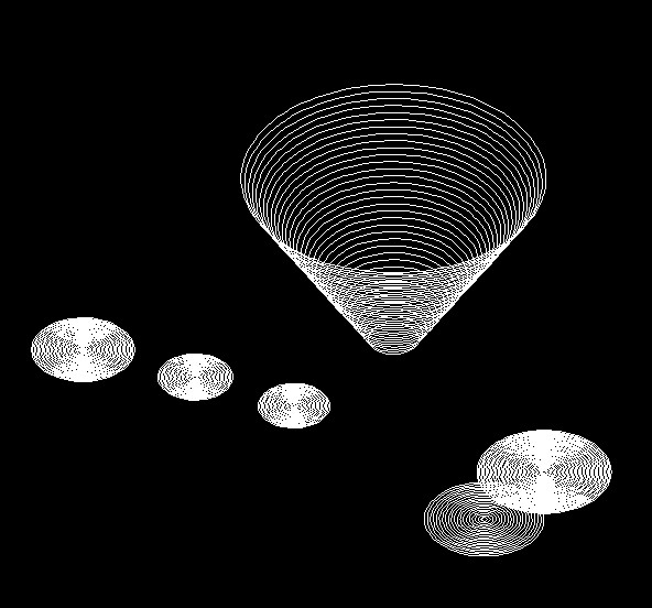
First post so cut me some slack if this isn't in the right spot! I have software that creates a script file and essentially dumps circles into AutoCad. The manual part is using rulesurf to connect them (each circle has a different 'z' elevation - and x,y for that matter). Basically, I'm trying to further automate the process and create the 3D image with minimal user input. I've played around with the rulesurf command in the .scr file but I'm not having any luck. Two of the circles and the rulesurf attempt is below - I add the radius of the circle to the center point's 'y' value in order to select the object circle 3.76,-4.83,-190.00 59.00 circle 3.72,-5.03,-310.00 59.00 surftab1 30 rulesurf 3.76,54.17,-190.00 3.72,53.97,-310.00 The weird thing is, when I look at the command window after the failed attempt, I can see my x,y,z point I use to find the circle being rejected When I type the x,y,z point in manually it never has issue finding the circle. I'm using ACAD 2015 with a acad3D.dwt file. Any advice would be great as I'm just getting started with my dive into .scr files and the POWER they hold! Recommended readings would be awesome too. I'm a darn good drafter now working on my engineering degree - so I'm not afraid to learn or take criticism! Thanks
-

Draw a maximum number of circles inside in polygon
teknomatika posted a topic in AutoLISP, Visual LISP & DCL
Hello! I've been here and here, and both are good jobs. But, as a challenge, I wanted a routine that would allow to draw inside a polygon within the largest possible number of circles with a radius value that would be provided as a variable. Example: -
In creating circles and arcs, they work fine, I can fit them, stretch them and make all my interior design details look nice. Often, when I use the move command (or other times/ways) the curved lines suddenly go faceted and no longer curves. When I move/copy item just next to itself, all is well. Seems to happen when I move the item from one space on the grid up to another place on the grid area. Once there, I can copy it, and the arc/curve returns on the copies item, but the original stays with the faceted sides. I spent an hour drawing a huge display of greenery, ivy leaves, etc. with 2 arcs simply face to face to create "leaves". The poly-lines seemed to stay with original curves, but the arcs and circles keep changing on me in my drawings. any curve ( So far I create all of mine through the circle and arc icon button commands) Sometimes moved within my grid area, and sometimes moved off the grid and moved back on again. I cannot say exactly when the format changes,, but I sure notice once I'm working on the final versions of drawings. Any advice to prevent this, & any advice to pick a complicated drawing of leaves/vines and return the whole thing back to curves? Current drawing; Limits; 500. , 500. / Grid spacing 0.2258 Snap is off. Ortho on and off - no effect. AutoCAD LT 2014 / HP DesignJet500 plotter / Windows 7 Professional / Dell Precision M6700 / Intel Core i7 2.60GHz RAM 8.00GB 64bit / Razer Orochi 2013 Mouse.
-
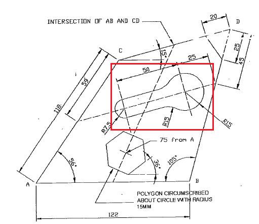
Hello. I need to connect two circles with different radius. Sorry, I don't really know how to explain my question using the right terminology or in the right words. So, here's the snapshot of what I need to draw, the one in the red rectangle.

-
Doing a drawing for the bridge wing of a ship at the minute in isometric, there is a bulkhead (wall) that is angled @ 11degrees and i need to put a rectangular window (with 100mm radius corners) and a circular penetration in a similar bulkhead....is it possible to make the iso circles/fillets look right on this? really got me stumped this one!!!
-
Greetings. I've been doing some very simpes routines. One of them is designed to draw a sequence of circles with a radius increment values and the z coordinate. Unfortunately, without my being able to understand (I am still basic), the routine works properly sometimes, not others, drawing circles but without changing the z coordinate. After the routine had wanted an evolution in order to draw a sphere composed of circles, but here I know that the requirement is complicated because the radius of each circle will have an appropriate value. I appreciate the help. ;;v1 (defun c:scir () (setq pnt1 (getpoint "\n Sets center point of 1s circle:")) (setq rcir (getreal "\n Sets the radius of circle:")) (setq rinc (getreal "\n Sets a radius increment:")) (setq incz (getreal "\n Sets z coord increment:")) (setq ncir (getint "\n Sets n of circles:")) (repeat ncir (command "circle" pnt1 rcir) (setq xpnt1 (car pnt1)) (setq ypnt1 (cadr pnt1)) (setq zpnt1 (+(caddr pnt1)incz)) (setq pnt1 (list xpnt1 ypnt1 zpnt1)) (setq rcir (+ rcir rinc)) );repeat (princ) );defun (prompt "\nType SCIR")
-
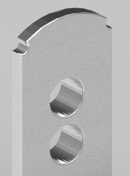
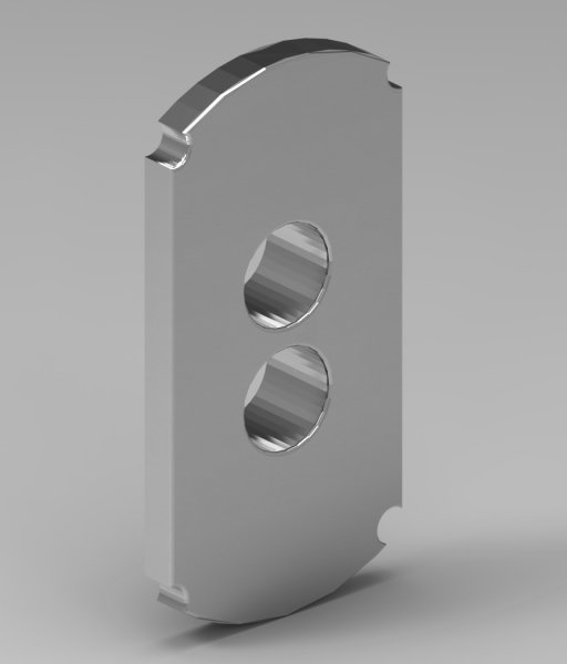
I could really use some help with this. I’ve been using AutoCAD for about eight years now for architectural support in 2D. Lately drawing models for my smaller parts and rendering really helps to get the message across. Problem is rendering. I can never remove the segmenting of arcs and circles even in the highest of setting. Does AutoCAD have fundamental problems with rendering solids? I’ve used 3rd party programs for rendering also with the same results. I must be missing something. Example of my setting: Viewres = 20000 Facetres= 10 Whiparc = 1 segments in a polyline curve = 30000 attached are samples of segmented renders. Thanks in advance.
-

Dynamic Blocks - Circles and Lookup Parameter / Actions
TheyCallMeJohn posted a topic in AutoCAD General
Hello All, I am having some difficulty with circles & lookup parameters in my dynamic blocks. I have two circles at the end of a rod and I want to have it set so that when the users selects equipment A using a lookup, circle 1 gets set to a certain radii and circle 2 gets set to a different radii. If a user selects equipment b, circle 1 gets set to a certain radii and circle 2 gets set to another different radii and so on so forth. Also I can not use my visibility parameter for this as it is getting used for something else in the block. Any help would be appreciated.