Search the Community
Showing results for tags 'isometric'.
Found 14 results
-

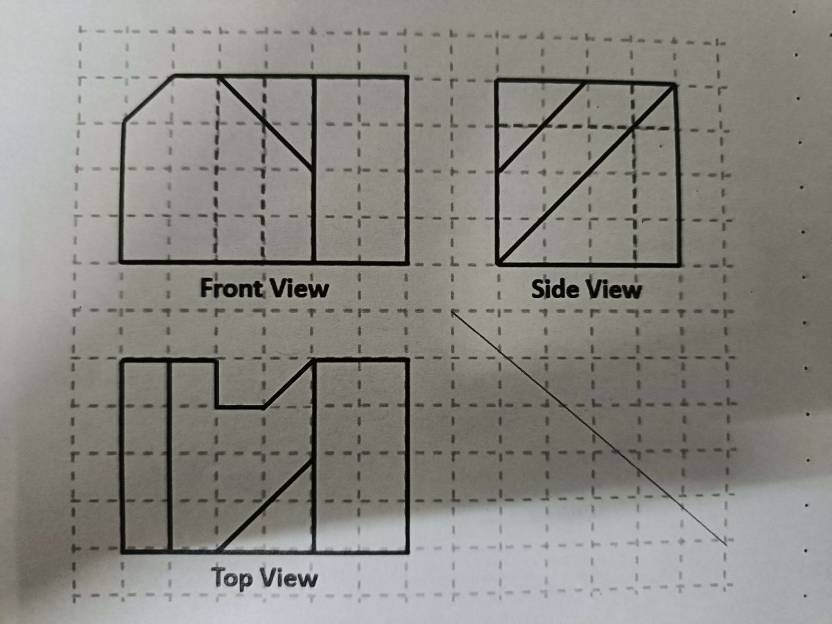
Need help to create an isometric view from first angle orthographic view.
CadLearner2023 posted a topic in AutoCAD Beginners' Area
Hi there, i need help on creating a isometric view by following this orthographic first angle projection. I've tried to use the command WSCURRENT to 3D modelling but still failed to complete the isometric drawing. Any idea or steps to be considered ?
-
i use isometric drawing in autocad , and i draw a line length 20mm autocad draw a line length 20 but if i use a lisp isoblocks.lsp https://autocadtips1.com/2012/03/21/autolisp-easily-create-isometric-blocks/ the lengt hof the lines change? why?is another isometric projection?
-
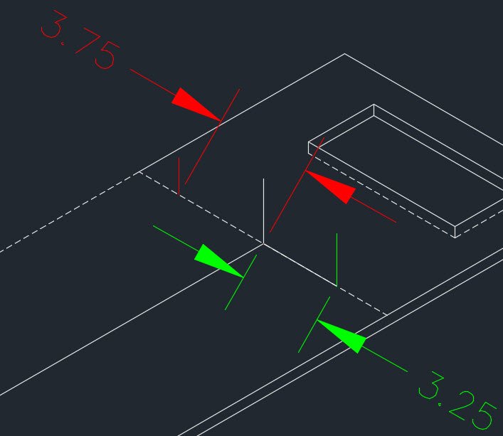
hello, sorry if post in the wrong forum, what is the correct way to offset a line in autocad Isometric drawing, i want to offset red line 3.25 in from mid point just like the distance in green, when i typed 3.25 in it turned out to be 3.75 in. Is that something to do with wrong plane? i can simply just draw a line command from midpoint 3.25 in but i thought there should be easier way. sorry i m new to Iso. Thanks
-

Creating Isometric slope hatches in AutoCAD 2014? HELP!
tmelancon posted a topic in AutoLISP, Visual LISP & DCL
Hello all, I work primarily in the piping industry and we do not use Autocad 3D Plant because we aren't in the design industry but rather more in the maintenance part of it. That being said we do not have the piping slope hatching functionality. See Photo for slope hatching example. We use this for 45 degrees, rolled 45 degrees and rolled 90 degree elbows. If someone can chime in a maybe share something that would be useful to us to aid in the automation of creating this hatch quickly I would greatly appreciate it. -
You can control the orientation of holes on a PCD while working in Isometric, but it's an intricate and tedious piece of projection. Here is an easier way. I hope this helps someone.
-
I have set my drawing background colour to a pale beige because it's easy on the eyes. Unfortunately, when I am using Isometric Snap the pickbox in the pointer is all but invisible (being white). I have searched the Drawing Window Colors dialog without success. Can someone tell me how to set the pickbox colour? Thanks
-
Hi all, trying to draw a hex nut in isometric...I've got the ellipse with the inside/outside dimensions but as far as placing the lines and connecting them to make the hexagon perimeter I keep coming up wrong.... any ideas?
-
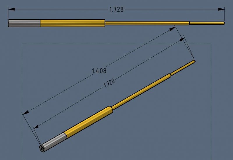
I have been racking my brain as to how to make this work and am at a loss so please help me figure this out. I have a simple assembly of a pin and hood. The pin has a spherical end and the hood has a fillet edge that continues to wrap spherically inward. When trying to dimension the OAL on the side view it is easy and obvious. When trying to do it on the iso view the measurements are never correct. I do not have a good point to choose from on the hood as it has a fillet edge not a square point, which would be easy. Without a flat surface to go off of and in the paper space there is no way to specify quadrants/edges/planes when annotating. The space bar trick helps but does still does not dimension to the right point. When I try to use the RETRIEVE DIMENSIONS action, I can get the OAL of the pin and OAL of the hood separately, but not as an assembly OAL. I tried to go into the assembly and create random sketches, planes, fake dimensions that might be used by the retrieve dim action, but to no avail. This is the simplest part I am using as a reference, I have much more elaborate parts that are giving me the same issue. It would seem straightforward, but for the life of me cannot find an easy way to get that simple OAL. Thanks for the help. Go Sun Devils!
-

How to do isometric view and top view in autocad?
gen_shao posted a topic in AutoCAD Beginners' Area
im doing both isometric view and top view of a floor plan in a single paper at the same time. the problem is ..when i change the view to isometric.. the drawing that is intended for top view changes to isometric view also.. how can i change the view of a single object to isometric isolatedly,, without affecting the other drawings and remain in its current position?? btw im using autocad 2007....thnx.. -
Doing a drawing for the bridge wing of a ship at the minute in isometric, there is a bulkhead (wall) that is angled @ 11degrees and i need to put a rectangular window (with 100mm radius corners) and a circular penetration in a similar bulkhead....is it possible to make the iso circles/fillets look right on this? really got me stumped this one!!!
-

Cursor doesn't display in isometric view?
trk97a posted a topic in AutoCAD 2D Drafting, Object Properties & Interface
When I switch from 2D top view to an isometric view my cursor disappears. This is a completely new drawing file so maybe something is not set right. Any suggestions are welcome. -
I am drawing an isometric drawing. In order to draw a dimension line, the tutor says I have to change the obliquing angle to s0 for left plane and -30 for right plane. I could find anything in: Modify Dimension Style Where should I change this angle?
-
Hello. I'm currently a freshman an engineering student at UVM. I'm in a basic autocad class now, and am only using orthographic and isometric views (don't know 3-d autocad yet). For a final project, I am constructing a treehouse using either a pentagon or hexagon shape. What neither I nor my professor can figure out is how one would build this using the iso setting. Using the ellipse to construct this seems to be the right way, but I can still not determine what the angles would be. Also, because it is to be done in isometric view, all the sides of either the polygon or pentagon would have to be true lengths (equal lengths). Any and all help is welcome. Thanks! -Alex
-
Hi, i'm wondering how to get orthographic views isometric view (with some dimentions) from an object ive already assembled with proengineer (student). Would be nice if somebody could point me in the right direction. Thanks