Search the Community
Showing results for tags 'modelling'.
Found 7 results
-
Hello Guys Im new to sketchup and only played around with photoshop and GIMP so im new to 3D modelling and only been on the program for around 3 hours. As you may have guessed i'm still pretty bad having not had time to properly practice. Anyway I am looking to design 3 wolves heads in to a metal side case of a PC.If its possible the coloured parts would be the bits that are cut out of the case .Eventually its a project as im in to PC case modding and would like to take it to a company and get it case cut in to the side. How would I go around this and is there a tutorial that could help me that you could think of. Any help would be a benefit right now as im completely stuck. Thank you in advance Ryan

-

Beginner: help with modelling 3d curved solids
dementia posted a topic in AutoCAD 3D Modelling & Rendering
Dear community, I'm a relatively new acad user, somewhat managing myself well with 2d drawing, and venturing into 3d drawing and modelling. I've struggled with some curved parts for the hull of a vehicle I'm designing, especially bringing it to be a solid object. I've been able to achieve the surfaces of the body I was looking forward to compose, however, I'm having what seems to be a very common problem, no watertight envelope. I've read about it and seems that Inventor is capable of stitching these minimal holes in the envelope. I acquired the program but really don't know how to use it. Could someone help me sealing this up to make a solid, whether it's inventor or autocad? My filesize is too big (more than 1mb), so cannot attach directly, here is download link instead: https://www.dropbox.com/s/ouzd1tzt3jll933/hull%20quarter.dwg?dl=0 Thannks! -

Draw pulldown showing the word modelling instead of icon
acarpenter posted a topic in AutoCAD 2D Drafting, Object Properties & Interface
I use Autocad 2013 and i use the classic set up. and last week i accidentally clicked and lost my classic set up. When i tried to pull up the icons and reset but nothing happens. I have managed to confiqure it back to autocad but the pulldowns are not showing the commands it should. the draw for example is just showing the word modelling. I presume that its been reset in some kind of 3d mode, has any one else come across this and is there a command or series of commands that convert it back to the normal 2d set up. Any help would be very much appeciated. thank you -
Right, I’m racking my brain here and I’m finally giving in and looking for assistance from the collective knowledge on the forum. I am having some mapping difficulties with regards to applying a jpeg as a material map onto a surface material. Below are the details. I have a surface model which was generated from topographical information. I have aerial photography of the area the topographical information is based on. The photography covers approximately 1000m2 area. The topography area in contained within this area, it is in the upper right hand corner of the square photo. I have applied planar mapping to the surface I resized the mapping area of the surface to suit the area that the photo covers (I created a boundary rectangle and adjusted the mapping size to suit). I created a customer material using the jpeg photo I applied it to the surface The image scale is set to 1000 All other settings remain as default settings. The mapping displays over my model, but its on the wrong location, i.e. information contained within the jpeg that is out with the topographical area is appearing on the model. When I turn off tiling the mapping disappears from my model completely. I have read a few tutorials today and went back to basics on a few trials by creating blocks and applying the material and scaling it that way. All behave as anticipated. Apart from this. Any help that could be given would be great. Thanks in advance G AutoCAD 2011 Windows XP Professional.
-
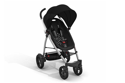
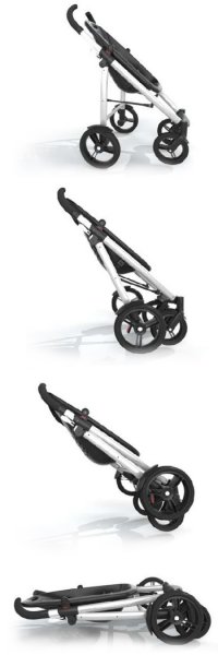
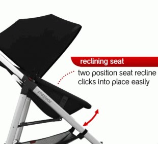
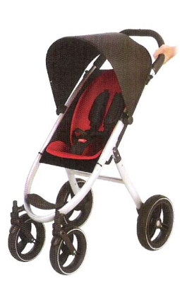
Hi CADTutor. I am new to this forum. I need some help on a project i'm currently trying to do and I have no idea where to begin. I am hoping some kind soul out there will show me the way.. I am fairly new to Solidworks but not a complete newbie. The main commands I know is the Extrude, Cut, Shell and other features. The bits I struggle on is the Sweeps, Reference gemometry, mates, and other stuff.. THe project i am working on is trying to make a pushchair/baby stroller in Solidworks. I have images of what I want to model, have the main measurements i need, i just to make it in Solidworks, Assemble and then test using the Simulation software... But i have no clue where to begin Someone please help! Images of the stroller push chair i want to model are at the end of the thread post. A breakdown of what I want to do: 1) I want to make the frame of the stroller + the wheels. With this assembled, I will be able to do an initial Displacement Test and check my Factor of Safety. 2) I want to make the seat and the Sunhood of the stroller. This will be added to the main assembly. 3) I want to make my Stroller have the ability fold, and the seat to be reclined backwards as shown in two of the images. Stroller's website: http://philandteds.com/products/push/smart By the way, I don't want to make the model using surfaces etc. THe main tool i need to make the frame and stuff is the Sweep. I am using Solidworks 2011 version. Thanks for reading, I appreciate any help that can be offered, Raz. Images of the Pushchair I want model: http://4.bp.blogspot.com/_pUw8FCLgav8/TR-t_-BjG1I/AAAAAAAAASA/riX1YaBq_30/s1600/phil%2526teds2.jpg
-

Where to look for fully dimensioned drawings? Please Help!
cancer24 posted a topic in Autodesk Inventor
Hi, I have been learning Autodesk inventor lately, and I am quite excited about it. I have been doing a lot, the problem though I need dimensions to model things, because I am at the beginning stages, and I don't have any sort of experience in design, I mean I have zero knowledge about design principles and philosophies. So my approach has been to imitate what I see, I get pictures like this http://iadesigns.com.au/53_Bevel_Gear_Support_exercise.jpg http://furnituredesignbank.com/Blog/Entries/2011/4/1_8_This_stool_can_be_made_in_various_heights._files/dimensioned%20drawing.jpg Like so, I prefer pictorial drawings, they are easier to understand that side views. I am sure there is somewhere to look for these kind of things, so please help me. I tried google images search engine.. key words like "dimensioned drawings", but no avail... Thank you very much! -
Hi guys im new to this forum and i have a question about inventor. is there a way to know ho much time i have spent on a modell or assembly? Ive been making some changes in some parts but i need to know if its really worth it, and how much modelling or editing time it takes. thank you very much and sorry for my bad english