Search the Community
Showing results for tags 'civil3d'.
Found 17 results
-

Need help automating object layer change based on OD
David B. posted a topic in AutoLISP, Visual LISP & DCL
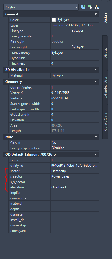
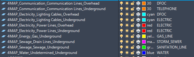
Good afternoon, One of our vendors has sent us several shp files with lines/polylines and ones with points. All the data comes in on a single layer, but I would like to sort the data with a LISP based on existing layers I've created and some of the Object data. Below is an example of the OD I want to use, and the layers I would like to have the objects sorted into. Could anyone help with some code that I could use to sort these objects? The OD table name will change depending on the file we receive, if that matters. Thanks
-
We regularly export Civil3D files to CAD so we can use them in either CAD and Revit. We have run into a few problems with this workflow, since any xrefs that aren't detached before exporting become blocks in the CAD file. Additionally, Revit automatically enables all the layers when you insert the CAD file, so you have to manually disable them again. I have created a simple lisp that detaches the xrefs and deletes the listed layers using code I pulled from various forums. However, I've got two issues: 1. The dellayers function claims to delete the DR_X_Text layer, but the layer and the entities on that layer remain in my drawing after running the command. 2. I'd like to princ the list of removed xrefs as well, but I'm not sure where to place that code. (defun c:Civil3DtoCAD (/) (c:detachxrefs) (c:dellayers) (princ) ) (defun c:dellayers (/ e) (foreach layer '("DR_X_Text" "_11-2606G1K-1-24" "_11-2607G1K-1-24" "_11-2608G1K-1-24") (if (setq e (tblobjname "layer" layer)) (progn (vl-catch-all-apply 'vla-delete (list (vlax-ename->vla-object e))) (princ "Layer ") (princ layer) (princ " deleted.\n") ) (progn (princ "Layer ") (princ layer) (princ " not found.\n") ) ) ) (princ) ) (defun C:Detachall (/ *error* mip:layer-status-restore mip:layer-status-save delete-xref-img-underlay delete-all-dict ) (vl-load-com) (defun *error* (msg) (mip:layer-status-restore) (princ msg) (princ) ) ;_ end of defun (defun mip:layer-status-restore () (foreach item *PD_LAYER_LST* (if (not (vlax-erased-p (car item))) (vl-catch-all-apply '(lambda () (vla-put-lock (car item) (cdr (assoc "lock" (cdr item)))) (vla-put-freeze (car item) (cdr (assoc "freeze" (cdr item))) ) ;_ end of vla-put-freeze ) ;_ end of lambda ) ;_ end of vl-catch-all-apply ) ;_ end of if ) ;_ end of foreach (setq *PD_LAYER_LST* nil) ) ;_ end of defun (defun mip:layer-status-save () (setq *PD_LAYER_LST* nil) (vlax-for item (vla-get-layers (vla-get-activedocument (vlax-get-acad-object)) ) ;_ end of vla-get-layers (setq *PD_LAYER_LST* (cons (list item (cons "freeze" (vla-get-freeze item)) (cons "lock" (vla-get-lock item)) ) ;_ end of cons *PD_LAYER_LST* ) ;_ end of cons ) ;_ end of setq (vla-put-lock item :vlax-false) (if (= (vla-get-freeze item) :vlax-true) (vl-catch-all-apply '(lambda () (vla-put-freeze item :vlax-false)) ) ;_ end of vl-catch-all-apply ) ;_ end of if ) ;_ end of vlax-for ) ;_ end of defun (defun delete-xref-img-underlay (/ count txt) (mip:layer-status-save) (vlax-for Blk (vla-get-Blocks (vla-get-activedocument (vlax-get-acad-object)) ) ;_ end of vla-get-Blocks (if (and (= (vla-get-IsXref Blk) :vlax-false) (not (wcmatch (vla-get-name Blk) "*|*")) ) ;_ end of and (progn (setq count 0 txt (strcat " Erase Xref and Underlay in " (vla-get-name Blk) ) ;_ end of strcat ) ;_ end of setq (grtext -1 txt) (vlax-for Obj Blk (setq count (1+ count)) (if (zerop (rem count 10)) (grtext -1 (strcat txt " : " (itoa count))) ) ;_ end of if (if (and (vlax-write-enabled-p Obj) (or (and ;_ XREF (= (vla-get-ObjectName obj) "AcDbBlockReference") (vlax-property-available-p Obj "Path") ) ;_ end of and (and ;_ UNDERLAY (wcmatch (vla-get-ObjectName obj) "*Reference") (vlax-property-available-p Obj "UnderlayName") ) ;_ end of and (= (vla-get-ObjectName obj) "AcDbRasterImage") ;_ IMAGE ) ;_ end of or ) ;_ end of and (VL-CATCH-ALL-APPLY 'vla-Delete (list Obj)) ) ;_ end of if ) ;_ end of vlax-for ) ;_ end of progn ) ;_ end of if ) ;_ end of vlax-for (mip:layer-status-restore) ) ;_ end of defun (defun delete-all-dict (dict) ;;; dict - dict name (like "ACAD_IMAGE_DICT", "ACAD_PDFDEFINITIONS" ... ) (vl-catch-all-apply '(lambda () (vlax-map-Collection (vla-item (vla-get-dictionaries (vla-get-activedocument (vlax-get-acad-object)) ) ;_ end of vla-get-dictionaries dict ;_ "ACAD_IMAGE_DICT" ) ;_ end of vla-Item 'vla-delete ) ;_ end of vlax-map-Collection ) ;_ end of lambda ) ;_ end of vl-catch-all-apply ) ;_ end of defun (vl-load-com) (delete-xref-img-underlay) (command "_-xref" "_d" "*") (while (> (getvar "CMDACTIVE") 0) (command)) (mapcar 'delete-all-dict (list "ACAD_IMAGE_DICT" "ACAD_PDFDEFINITIONS" "ACAD_DWFDEFINITIONS" "ACAD_DGNDEFINITIONS" ) ;_ end of list ) ;_ end of mapcar (command "_.regenall") (command "_.externalreferences") (princ) ) ;_ end of defun (defun c:detachxrefs ( / block-lst xref-lst nxt-blk n) (PROGN (SETQ block-lst (LIST (TBLNEXT "BLOCK" T))) (SETQ xref-lst NIL) (WHILE (SETQ nxt-blk (TBLNEXT "BLOCK")) (SETQ block-lst (APPEND block-lst (LIST nxt-blk))) ) ;_ end of WHILE (FOREACH n block-lst (IF (AND (ASSOC 70 n) (EQ (BOOLE 1 4 (CDR (ASSOC 70 n))) 4)) (SETQ xref-lst (APPEND xref-lst (LIST (LIST (CDR (ASSOC 2 n)) (CDR (ASSOC 1 n))) ) ;_ end of LIST ) ;_ end of APPEND ) ;_ end of SETQ ) ;_ end of IF ) ;_ end of FOREACH (IF xref-lst (c:detachall) (PROGN (PRINC "\nNo References to Detach... ") (PRINC) ) ) ;_ end of IF (PRINC) ) ;_ end of PROGN ) ;_ end of defun
-
I was wondering if anyone knows of a way to stretch alignment labels in a label group once they're already in the drawing - straight out from the origin point in a straight line. There is a stretch option for the labels but instead of stretching the label straight out in a linear way, it flips the text 90 degrees and adds a leader with an arrow. But we can't use that since it's not what DOT wants. You could obviously explode the entire group and adjust everything manually. But trying to avoid that. It seems odd that it would flip the text 90 and add a leader with an arrow. There must be some setting built in to civil3d that tells the program how to do this. Is this an option that can be tweaked though? Is this a feature embedded within the label group settings somewhere? We just want to be able to stretch individual labels straight out from the origin point in a straight line without flipping the text - in cases where individual labels overlap key features and lines on the plan sheet. Thanks! ChriS
-
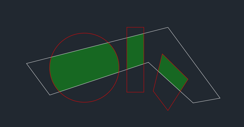
I have two polygons. One is my corridor (see white), and my other are disturbances (see red). I'm looking for a lisp that creates polygons everywhere where there is an overlap between the two (see green hatch). I currently have a lisp that gives me the area of the intersecting hatch but it is only a single use. I want to be able to click the white boundary layer and then the red intersecting layer and have it make intersecting polygons between those two.
-
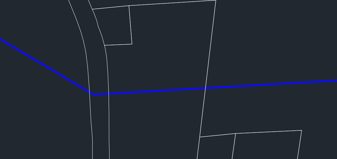
I have a line that crosses through multiple polygons. Is there a LISP to give me a count of how many polygons this line goes through?
-
I have recently been asked to learn the Pressure Network part of Civil3D for an upcoming project but there are a couple of things I'm having trouble with. I will need to create approx 25km of water main supply pipe. I have worked out how to create pipes manually and assign the entire line to a pre-designed profile instead of offsetting from surface model with no real problems. But for the length and complexity of pipe involved the "Create pressure network from object" tool would probably speed things up enormously. My problem is that although this tool adds bends etc with ease, it does not seem to allow for pipe deflections at joints. ie. if the bend is actually 46 degrees it does not simply allow for a 0.5 degree deflection at the joints at each end. It instead realigns the downstream pipe and introduces 11.25 bends here and there to fix it's mistake. Also the same with straight pipes that might have a 1 degree deflection somewhere to follow road alignment. Instead of simply allowing the deflection between straight pipes, it introduces an 11.25 bend with deflection at it's joints over and above that allowed in the parts catalogue. Is there a setting or a box to be ticked that I am missing? Or am I destined to do all of the design manually? Any help will be greatly appreciated.......
-
I'm Labeling flow information of a pipe (RCB to be specific, but I'll use pipe), and almost at random parts of the expression disappear leaving me with an error for the labels and having to go through the tedious process of fixing the expressions. This happens with several expressions but the same information is missing. So for example: HYDRAULIC RADIUS RCB: (AREA_OF_PIPE_RCB)/(2*{Inner Pipe Height}+2*{Inner Pipe Width}) Becomes (AREA_OF_PIPE_RCB)/(2*+2*) It always seems to be losing the information related with the pipe's property. While it does it this when I restart AutoCad it doesn't do it everytime, I cant find to seem to find any pattern to when it does it. I'm new here, I did a quick search and didn't find anything, I asked a few of the veterans in my office and they haven't seen anything like this, so hence I'm posting here. I appreciate everyone's time.
-
Recently upgraded to Civil 3D 2015 from 2013 but am having trouble using one of my most used AutoLISP commands to connect a string of points (connectpts) When I load the command I get the following error message; "; error: Automation Error. Problem in loading application" Any ideas out there? This is file; ;|Platform: AutoCAD Civil 3D Routine to draw 3dPoly between points with identical descriptions, in ascending Pt# order. by Jeff Mishler, July 25, 2007. Tested only in C3D2008. Type (vl-load-com) at command prompt first. |; (vl-load-com) (defun c:Connectpts (/ appstr coords desc grps pline point point#s points pt qbldr ss tmpgrp vrsn ) (setq vrsn (vlax-product-key)) (cond ((vl-string-search "R16.2" vrsn)(setq appstr "3.0"));;2006 ((vl-string-search "R17.0" vrsn)(setq appstr "4.0"));;2007 ((vl-string-search "R17.1" vrsn)(setq appstr "5.0"));;2008 ((vl-string-search "R17.2" vrsn)(setq appstr "6.0"));;2009 ((vl-string-search "R18.0" vrsn)(setq appstr "7.0"));;2010 ((vl-string-search "R18.1" vrsn)(setq appstr "8.0"));;2011 ((vl-string-search "R18.2" vrsn)(setq appstr "9.0"));;2012 ((vl-string-search "R19.0" vrsn)(setq appstr "10.0"));;2013 ((vl-string-search "R19.1" vrsn)(setq appstr "11.0"));;2014 ((vl-string-search "R20.0" vrsn)(setq appstr "12.0"));;2015 (t (alert "This version of C3D not supported!")) ) (if (and appstr (or *acad* (setq *acad* (vlax-get-acad-object)) ) (or *AeccApp* (setq *AeccApp* (vla-getinterfaceobject *acad* (strcat "AeccXUiLand.AeccApplication." appstr))) ) (or *AeccDoc* (setq *AeccDoc* (vlax-get *AeccApp* 'ActiveDocument)) ) (setq ss (ssget ":S:E" '((0 . "AECC_COGO_POINT")))) ) (progn (setq pt (vlax-ename->vla-object (ssname ss 0)) desc (vlax-get pt 'RawDescription) grps (vlax-get *AeccDoc* 'PointGroups) tmpgrp (vlax-invoke grps 'Add "__TEMP__") ) (setq qbldr (vlax-get tmpgrp 'querybuilder)) (vlax-put qbldr 'IncludeRawDescriptions desc) (if (> (length (setq points (vlax-get tmpgrp 'Points))) 1) (progn (setq point#s (vl-sort points ' (setq points (vlax-get *AeccDoc* 'Points)) (foreach pt# point#s (setq point (vlax-invoke points 'Find pt#)) (setq coords (append coords (list (vlax-get point 'Easting) (vlax-get point 'Northing) (vlax-get point 'Elevation) ))) ) (setq pline (vlax-invoke (vla-get-modelspace *AeccDoc*) 'Add3dPoly coords)) (vla-put-layer pline (vlax-invoke *aeccdoc* 'getvariable "Clayer")) ) ) (vlax-invoke qbldr 'clear) (vlax-invoke grps 'remove "__TEMP__") ) ) (princ) )
-
 I need to turn off the line weights in layout. Civil 2014 had an icon at the bottom just like all the rest of ones I have worked with. I do not see anywhere to toggle line weight on 2015. Please help!
 -
In Civil 3D, under the Insert tab, there is a menu selection that allows you to insert a Google Earth image directly from Google Earth. This image is inserted to match the coordinates of your ACAD drawing. However, it does not always match the known correct line work, depending on the drawing settings. For example, if one was working on a project in California in Cal. Coordinate System, zone 2, the available coordinate systems (under the Units and Zone tab) could be HARN, NAD27 or NAD83. Then there is the transformation settings (under the Transformation tab) like: Sea Level Scale Factor and Grid Scale Factor. My question is: What are the best drawing settings to use for the best fit between the Google image and the drawing so that the image matches linework that you know is correct (based on certified surveys)? Thanks.
-
Hello all, How can I create a smooth transition between subassemblies with different daylight slopes? I have a corridor with 2 subassemblies used. I set the regions up so type 1 is from Sta. 0+0 to 0+100, type 2 from 0+100 to 0+125, and then from 0+125 to end is type 1 again. The daylight slope for type 1 is 1.5:1 and it is 100:1 for type 2. Thanks in advance, Kyle
-
I'm wondering how to generate curves for alignments based on monuments. Say I have two monuments tha represent the start and end of a curve. The old method is to draw two perpendicular lines from the monuments and draw a circle with a radius where those lines connect. What is the new way using Civil 3d? Thanks.
-
I've got an assembly of a crown road and daylight sloping running along a corridor. At one point there is a retaining wall along the shoulder which I want to daylight to (the rest of the road daylights to the original ground). I've inserted a "LinkOffsetandSlope" subassembly that will do what I want in the area of the wall (represented by a feature line). But for areas of the road where there is no wall, it still shows a link running to the default offset. Is there any way I can make this work without making another assembly and separate region? Thanks...
-
I am using ACAD Civil 3D 2011 and when you stop the cursor in a surface area, a pop up info window shows data such as surface elevation, station offset etc... The problem I am having is the font is light grey over a cream colored background which I find hard to read. Is there anyway to change the font and background color for this information pop up window? I have tried the accessability options under Windows (using windows 7) with no help. Our computer administrator in our office has blocked some of these accessability options so if it works for you, let me know anyway and I can request our administrator to help me. Thanks in advance for your help.
-
I have successfully created a whole range of particular settings for labeling my points (which are topos points with the headers of N,E,el) in the Label Style Composer and created a new style particularly for these kinds of points. Actually, i created 3 different Label Styles based on the description of the topo point) My predicament, is that clients will send me their .dwg files, and i have to import the points i collect onto there drawing which obviously don't have all the label styles I just learned to create so the points don't label correctly and i have to re-create all the styles each time?! question: How can I apply my Point Label Styles onto another .dwg? TIA!!
-
I have finished all my subdiviions designs in Civil3D CAD ( roads, profiles, etc...) and am getting ready to "cut" all my sheets (25 sheets) to be able to issue the construction documents. I have experimented with the Plan Production Tool (Viewframes,Sheets,etc...) I like the fact that it can actually get the profiles legible at the right scale,etc... I like the automated features: Matchline Text,etc... QUESTION: Does any consulting company REALLY use this "wizard" or is there a ? QUESTION: How can I "edit" the SHEET TEMPLATE that Plan Production Tools is using (I have my own customization I would like to do)...How do I access ALL the Settings for the Plan Production Wizard ? **NOTE: I feel that the rest of the Civil Engr Indutry is NOT switching to Civil3D but sticking to the LandDesktop Transition..... After several months, I am finally convinced that Civil3D is more flexible....I am all alone in trying to create Construction Documents with Civil3D ?***
-

CLEAN INSTALL OF WINDOWS 7 (replacing 64 VISTA) Civil 3D 2011 Database Backup?
Old Timer posted a topic in AutoCAD General
I am getting ready to perform a CLEAN install of Windows 7 (to replace VISTA) Are all the Civil3D 2011 "Database" (Surfaces, Alignments, Style Settings,etc...) sotred within each .dwg file, or is there a master database faile ? I am NOT using AutoCAD Vault Any tips on the reinstall to be able to get all my settings, plot style EVERYTHING, back to where they were ?

.thumb.jpg.09a08ecad2685cb2c8053165bd65e191.jpg)