Search the Community
Showing results for tags 'polar'.
Found 9 results
-
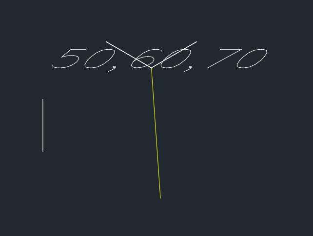
Hello all - I'm jim - New to forum, and auto cad. Over the last few weeks ive been using this site and others to learn AutoCad. I have gleaned lots of useful information however i'm struggling with UCS rotations/ Drawing 3D in a lsp. I'm half way through developing my first lsp that calculates the difference in X,Y,Y. It then draws lines showing deviation directions (for example deviation from design). X and Y devition lines seem to be working ( not fully tested negative coordinates yet) but I cannot resolve the Z line. I have highlighted area that is causing problems. and have attached a screen dump of current results. I know it is probably somthing simple I am missing, but I think i have been looking at the problem t0o long, with too much autocad inexperience If anyone has any ideas or pointers please let me know. Regards JM ;Written by JM 2019 ;STILL UNDER CONSTRUCTION (defun rtd (r) (/ (* r 180.0) pi)) ;Angle conversions (defun dtr (d) (/ (* d pi) 180.0)) ;Angle conversions (defun c:delta (/ p1 p2 x1 x2 y1 y2 z1 z2 xp yp zp dx dy dz coorddiff Tolerence) (command "_UCS" "World") ;Ensure WCS is current (setq osm (getvar "osmode") ocmd (getvar "cmdecho") textStyle (getvar "textstyle") ) ;(setq Tolerence (getdist "\nTolorence in mm : ")) (while (setq p1 (getpoint "\nPick Design Position: ")) (setq x1 (car p1)) (setq y1 (cadr p1)) (setq z1 (caddr p1)) (setq p2 (getpoint "\nPick Asbuilt Position: ")) (setq x2 (car p2)) (setq y2 (cadr p2)) (setq z2 (caddr p2)) (cond ((<= x1 x2) (setq dx (rtos (- x2 x1))) (setq xp (polar p2 (dtr 0) 50)) (command "line" p2 xp "") ) ;_ end of the first condition x ((> x1 x2) (setq dx (rtos (- x1 x2))) (setq xp (polar p2 (dtr 0) -50)) (command "line" p2 xp "") ) ;_ end of the first condition x ) ;_ end of cond statement for X (cond ((<= y1 y2) (setq dy (rtos (- y2 y1))) (setq yp (polar p2 (dtr 90) 50)) (command "line" p2 yp "") ) ;_ end of the first condition y ((>= y1 y2) (setq dx (rtos (- y1 y2))) (setq yp (polar p2 (dtr 90) -50)) (command "line" p2 yp "") ) ;_ end of the second condition y ) ;_ end of cond statement for y ;**********************************************************Rotation Causing 3D Line issue? (cond ((<= z1 z2) (setq dz (rtos (- z2 z1))) (command "_UCS" "y" -90) (setq zp (polar p2 (dtr 180) -50)) (command "line" p2 zp "") ) ;_ end of the first condition z ((> z1 z2) (setq dz (rtos (- z1 z2))) (command "_UCS" "y" -90) (setq zp (polar p2 (dtr 180) 50)) (command "line" p2 zp "") ) ;_ end of the second condition z ) ;_ end of cond statement for z ;**********************************************************Rotation Causing 3D Line issue? ;;Displayes co-ordinates (command "_UCS" "World") (setq coorddiff (strcat dx "," dy "," dz)) (command "text" "j" "c" p2 25 -45 coorddiff) ) )

-
Working on a utility to rotate polar type array half the angle between items to create a stagger effect of multiple concentric arrays. As far as my research turned up, there is no lisp property for the center point of the array. An array seems to be an anonymous block who's insertion point is always WCS (0 0 0), so if I apply a rotation property it does it from that point and not center point of array. Solution 1: Select the array, highlight grips with (sssetfirst), (getpoint) the center grip the rotate from that point... [not crazy about this option] Solution 2: Select the array, run the list command and extract the center point property from the log file [works marginally as the precision is only 8 decimal places so it ends up displacing it slightly] Any ideas?
-

Dynamic Block Copy/Rotate or Polar Array?
rhgrafix posted a topic in AutoCAD 2D Drafting, Object Properties & Interface
I am trying to make a dynamic block to somewhat mimic the 3D Revolve command, since I can't Sweep or Revolve 3D entities in the dynamic block, I want to fake it by making a revolved curved piece that travels 5° increments of a circle at a time, the dynamic part would be to make it copy itself end to end using the same axis as the part. I tried polar and rotate, they won't copy AND rotate, they always stay in a straight line. Anyone know how to do this? Thanks! R.L. Hamm -
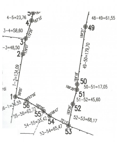
 Hi everybody, I've been reading tutorials about entering surveyor data, but still there is something I don't get it. Let's say I want to draw this scan in autocad (I already know how to enter relative xy/polar coordinates). I guess I should start the polyline at point named 1 and then enter @134.09 Segment 1-2 is visible less than 90º north, but even if I draw a visual aproximation angle for 1-2 to start de drawing, how would I then add the second segment 2-3 with the new bearing respect 1-2? How would I get a true to scan polygone? I will be gratefull of there is any explanation/example. Thanks. Paul
-

use command or button during a command
Sandervp posted a topic in AutoCAD 2D Drafting, Object Properties & Interface
Is it possible to use a command or button when you are drawing something? For example; I've made a toolbar for changing the polar angle into different angles. One for 30 degrees, one for .... degrees, etc. If I am drawing a polyline, and I need to change this angle, I can not use any button from this toolbar, otherwise the command stops. I can use the polar button to change the angle, at the bottom of the screen, between the other status toggles. I can use these status toggles any time. But because I need to switch very often, it takes a lot of time to use this. I also want to use the "snapang" command during this (or an other) command. If I need to change the angle of the polyline, just select 2 magnet points and my angle is oke. At this moment, I need draw the first part of a polyline, folowing change the snapang angle, draw the second part of the polyline and at last, use "pedit" to join the 2 polyline parts together. In short; I want to change my toolbar buttons so I can use them just like the status toggles. Usable at any time. Thank for your advice or solution. -

Polar tracking problem
SAFeSTeR posted a topic in AutoCAD 2D Drafting, Object Properties & Interface
Hi, I've always used polar tracking instead of ortho mode where possible, but just recently I've noticed that it seems to be a bit 'off' when drawing verticle lines. I first noticed this issue a few days ago when I offset a horizontal line but the extreme right verticle line would not trim. When I zoomed right in, the lines were not touching. I made a few tests by drawing 6 verticle lines, 2 each at 1000, 2000 and 3000 units in length, using polar tracking of course. I looked at the co-ordinates of all the lines vertices and the X values did not match, indicating a diagonal line, albeit very slight. However, when I compared these X values I noticed that for every 1000 units the difference was between the vertices increased by 0.11 units, which seemed a bit uniform and something was at fault for these fluctuations. I also drew some lines with ortho mode activated and the lines were perfectly straight. Has anyone else experienced this or have any ideas as to why this may occur? Is there a 'fix' or some things I can check? Could it be a bug (although this has never happened to me until recently)? I know the difference is negligible, but at the same time it's bugging me a little bit. Thanks in advance. -

Placing Object Not Locking with XLINE
D1-Xen posted a topic in AutoCAD 2D Drafting, Object Properties & Interface
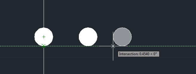
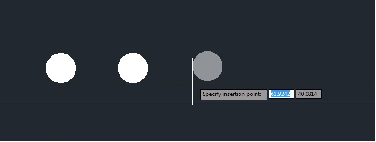
Hi AutoCAD members, I have a very frustrating issue with placing my repeated pattern of holes. I want my holes to be equally spaced from one & another, but the XLINE can only start tracking from the 1st Circle. ie: each circle have to be 0.25 mm apart from each other. Worked well for the 1st one, but the second one does not lock on the line anymore. Please tell me what function I need to enable to do this. Refer to attachment for more info. Thank you very much in advance. Can track from Circle 1 >>> But cannot track from Circle 2, why??? >>>
-

insert block at distance & angle from first block, then repeat until stopped
BudPerry posted a topic in AutoLISP, Visual LISP & DCL
In this portion of a continuing program I'm putting together, a 4' block is inserted at a user point at a defined angle, then it is again inserted but this time 4' away at the same angle so that the two blocks form an 8' line. This is continued until the user stops the program. However, when the second block is inserted, it is rotated correctly but inserted somewhere north of where it is supposed to be. Obviously my polar calc or something is off: (defun c:blockinsert () ; ; ; ;part 5 of overall program ; ; (setq p1 (getpoint "\nSELECT POINT: "));user inputs first point (setq p2 (getpoint "\nSELECT NEXT POINT: "));user inputs second point - for use in part 6 of program ; (setq ang1 (angle p1 p2));get angle from user points (setq angreal (* 180.0 (/ ang1 pi)));convert from radians to degrees ; (setq blockpt "@48<");create a string that puts the next block at 48 inches away at same angle - from first point ; (command "_insert" "I:/documents/pog-panel-4" P1 "1" "1" angreal "1" "category text" "lf");first insertion at first point with two attributes filled ; (setq nextpoint (polar p1 angreal 48));add 4' from p1 at same angle (setq nextp (strcat blockpt angreal));this line is wrong, but I can't figure out how to get the info into the command line... ; (command "_insert" "I:/documents/pog-panel-4" nextp "1" "1" angreal "1" "category text" texttwo) ;insert 4' from last one ; ; ;now I need to add a line that will increase the amount from 4' to 8', ;then to 12', and so on in multiples of 4' - the block is 4' long ;until the user hits escape to stop the block insertions ;maybe use the repeat function? ; );end defun Any ideas on how to correct the insertion and how to create the repeat function and user break? -
So i am confronted with this All my polar tracking options are turned to Zero. (sorry, no pic) strangly enough its does give me one tracking option (read line) wile drawing at 5° and when i draw a square it seems like my plane is off a bit (prolly 5°, looks like a perspective) Tried fiddling around with the DSETTINGS command but nothing goes. so i s my plane off, UCS off, am i a retard Hopefully this is a simple answer , also i get sometimes 1 out of 10 times an innorect SNAP ( snap to a point and its off by a 0,x margin. i Maybe this is connected? I tried google-ing and all but nothing goes. Hope i could get some help here, TNX.