Search the Community
Showing results for tags 'split'.
Found 7 results
-

Trim split hatch with holes problem !! Why after trim hatch there is holes in trimmed
LULU1965 posted a topic in AutoLISP, Visual LISP & DCL
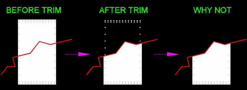
Trim split hatch with holes problem !! Why after trim hatch there is holes in trimmed parts. HATCH TRIM.dwg
-
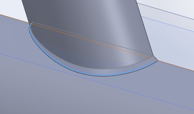
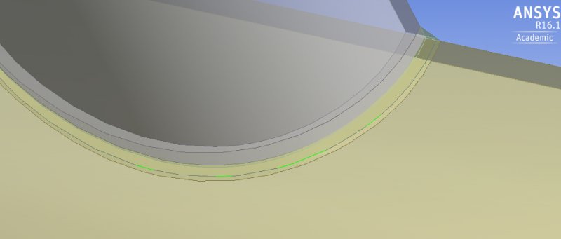
I am having a problem with Solidworks discreetizing 3D curved lines which is giving me problems down the road when importing my model into Ansys DesignModeler. I'll illustrate the problem by way of example: I have a number of bodies that I want to "cut up" for better meshing. In the instance I have attached, I used a slightly over-sized sketch of the chord profile and the split feature to divide the weld into two sections. As you can see in the first attachment, the resulting split *appears* to be a continuous line in Solidworks. This is want I want. In Ansys, however, the continuous line is broken up into discreet segments (see attachment two). I'm fairly certain this issue is on the Solidworks side, but if there are any Ansys experts who think otherwise, I'm happy to explore all options. I've sunk the better part of a few days into this issue and I can't seem to move forward with it.
-
Is there a way to split a single part in an assembly in order to show two separate halves during an animation. Scenario: My company wants to split a 40 ft shipping container in half to scab in a 4' section to make a 12' wide container. I have designed a jig on tracks to show how the container can be split and half of the container to be rolled away to allow for the "scab" to be built in the middle. IS there a way to animate this in Inventor.. The container is in the assembly model as a single part.
-

3D Splitting and lofting of a metal plate
paisis123 posted a topic in AutoCAD 3D Modelling & Rendering
Hello guys. I been requested by my company to start a bit in 3D work. (after 8 months of working here.) Anyway, to sum up my problem, I will break it down for you so this issue can be resolved and allow others to learn from this post as well. 1. Summary on what I'm trying to do. Basically we are trying to make a 3D plate (in this case a 2" thick piece of steel) and have a 3D hollow shape inside. Its split into Top and bottom, as shown as the below picture. I have tried the loft command (which I just learned off within the past hour or so) and it indeed works. But I wish to use its as the opposite, where the middle is hollow and the rest is a solid object. I have tried the loft command (which I just learned off within the past hour or so) and it indeed works. But for the life of me does not know how to get it as one big object with the middle shape hollow. Am i missing a step or is it another command completely? Also, once the object has been created, I want to split the object on its X axis mulitple times, almost like an exploded view. Each split will have its own set of top and bottom orifices which will represent multiple plates. Is there a way to do that? Also is there a way to gain and separate the top and bottoms of these newly split plates? Here is the drawing file as well to work on -> 3D-MK1.dwg
-
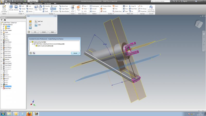
Hi, I want to cut a section of a part and make it into a new section without the constructional elements - planes, axis and so on on which it actually depends. I tried to create a solid body of it using the split tools. However in sectioning the part I want, It also included a bit of the original part with it due to the cutting tool being a plane (it does not accept two planes as cutting tools).. I re-use split with the solid body and a new plane but through it accept it, applying ok give an error dialogue box. Does anybody knows the solution to the problem. Thanks in advance.
-
Hello, I've made one very useful tool. It's called MLINE SPLIT and you guessed what it does. However it doesn't work on first and second vertices (1 and 2 vertex), and that is real mystery for me. Why are these vertices so different than all the other vertices. Below is my VBA code: Public Sub MLineSplit() On Error GoTo eh Dim ent As AcadEntity Dim p1 As Variant Dim p2 As Variant Dim x As Double Dim y As Double Dim atst As Double Dim min_atst As Double Dim taskas As Double Dim atst_nustatytas As Boolean Dim dblVertices() As Double Dim dblVerticesCnt As Double Dim dblVertices2() As Double Dim dblVerticesCnt2 As Double Dim sset As AcadSelectionSet Dim perdavimui As Variant Dim obj As AcadMLine Dim obj2 As AcadMLine Dim varpnt As Variant Dim krd(2) As Double Dim aa As Integer Dim objEnt As AcadMLine Dim objEnt2 As AcadMLine ThisDrawing.Utility.GetEntity ent, 1, "Select MLINE: " p2 = ThisDrawing.Utility.GetPoint(, "Select the SPLIT point in MLINE: ") x = p2(0): y = p2(1) atst_nustatytas = False dblVerticesCnt = -1 dblVerticesCnt2 = -1 'randam artimiausia If TypeOf ent Is AcadMLine Then 'AcadBlockRef isrinkimas Set obj = ent 'ThisDrawing.SetVariable "CMLSTYLE", obj.StyleName For aa = 0 To UBound(obj.Coordinates) Step 3 'MsgBox Str(obj.Coordinates(aa)) & "," & Str(obj.Coordinates(aa + 1)) & "," & Str(obj.Coordinates(aa + 2)) atst = DistanceBetween(obj.Coordinates(aa), obj.Coordinates(aa + 1), x, y) If (atst_nustatytas = False) Then min_atst = atst atst_nustatytas = True End If If atst min_atst = atst taskas = aa End If Next aa Else MsgBox "Must select MLINE!" Exit Sub End If Set perdavimui = obj.Copy Set obj2 = perdavimui 'Exit Sub For aa = 0 To UBound(obj.Coordinates) Step 3 'MsgBox obj.Coordinates(aa) 'MsgBox obj.Coordinates(aa + 1) 'MsgBox obj.Coordinates(aa + 2) If aa >= taskas Then dblVerticesCnt = dblVerticesCnt + 3 ReDim Preserve dblVertices(dblVerticesCnt) dblVertices(dblVerticesCnt - 2) = obj.Coordinates(aa) dblVertices(dblVerticesCnt - 1) = obj.Coordinates(aa + 1) dblVertices(dblVerticesCnt) = obj.Coordinates(aa + 2) End If If aa dblVerticesCnt2 = dblVerticesCnt2 + 3 ReDim Preserve dblVertices2(dblVerticesCnt2) dblVertices2(dblVerticesCnt2 - 2) = obj2.Coordinates(aa) dblVertices2(dblVerticesCnt2 - 1) = obj2.Coordinates(aa + 1) dblVertices2(dblVerticesCnt2) = obj2.Coordinates(aa + 2) End If Next aa If ThisDrawing.ActiveSpace = acModelSpace Then If dblVerticesCnt >= 5 Then obj.Coordinates = dblVertices If dblVerticesCnt2 >= 5 Then obj2.Coordinates = dblVertices2 Else If dblVerticesCnt >= 5 Then obj.Coordinates = dblVertices If dblVerticesCnt2 >= 5 Then obj2.Coordinates = dblVertices2 End If obj.Update obj2.Update Exit Sub eh: MsgBox "Error number: " & str(Err.Number) & " . Description: " & Err.Description End Sub
-
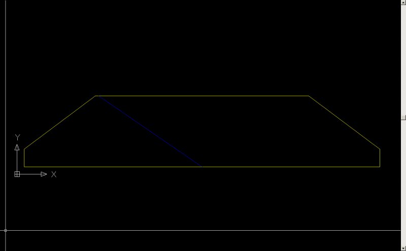
Hi, I'm trying to divide up a closed polyline with the blue line that intersects with it. I'm able to get the vertices for the intersection points. The end result should have 2 separate closed polylines. I've checked on the internet, and found some Lisp code, which unfortunately, I do not know how to interpret Does anyone know how to go about it? I'm progamming in C# .Net. Thank you. Special cases I will need to work out later: 1) One of the intersection points are on a vertex. 2) Both intersection points are on different vertices. 3) Both intersection points are on the same axis, i.e. the blue line is on one of the edges.


.jpg.7cbb90048bb1b34a73db6d6b2b3c96e4.jpg)
.jpg.dd560eb19c1fb867645719d66f15ba7d.jpg)