Search the Community
Showing results for tags 'tubes'.
Found 1 result
-
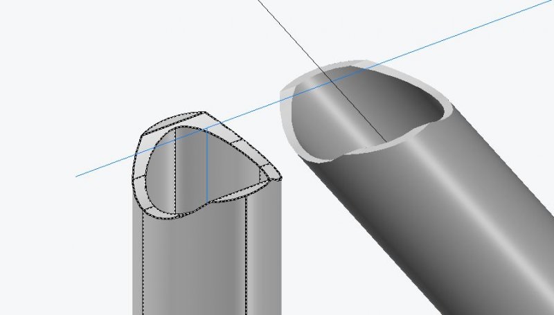
I have been struggling with this issue for weeks using Acad2012, Win 7. To draw the cope end I subtract one tube from the other, this creates a taper from wall thickness t at the intersection of the inner tube face to zero at the intersection of the outer wall face. This loss of wall thickness is not ideal. To get rid of this less than full thickness material I create a slicing plane through intersection of non-cut tube 1 and the inner wall of the tube to be cut, I establish this point by drawing a 2D cross section. I realise this a bit of a hack and it never works out spot on as the slicing plan never seems to match exactly the intersection point of the 3D tube inner wall. I have tried to get a work around. ie: - drawing a tube inner radius only subtracting from that then shelling-this only re creates the taper. -offsetting the intersection edge of the inner wall and trying to project onto outer at 90deg-this does not offset correctly due to the complex geometry. I was hoping the COPE file from SEANT post in the Customisation forum may answer my problems but I cannot get to work and would like to find out if this can be acheived using in built functions or methods? If anyone can provide me some help with the following I would be really grateful: 1. How to create a mitre maintaining full wall thickness. 90 degree intersections. 2. How to create a mitre maintaining full wall thickness. Non 90 degree intersections. 3. How to create a mitre maintaining full wall thickness. Tubes angled in 2 planes ie: for triangular space truss. 4. How to create a mitre maintaining full wall thickness. Tubes angled in 2 planes centres lines not coincident ie internal members offset to enable 2/3 to meet at same node. 5. How to deal with the above when using non round tubes.