All Activity
- Past hour
-

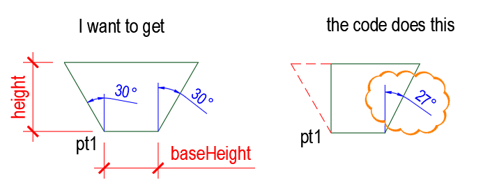
The coordinates of the trapezoid
marko_ribar replied to Nikon's topic in AutoLISP, Visual LISP & DCL
Untested, but it should work IMHO... (defun c:DrawTrapez30 (/ baseHeight height angle radian topBase pt1 pt2 pt3 pt4) (initget 7) (setq baseHeight (getreal "\nEnter the size of the bottom base: ")) (initget 7) (setq height (getreal "\nEnter the height of the trapezoid: ")) ;; Angle in radians (setq angle 30) (setq radian (* angle (/ pi 180.0))) ;; Determining the starting point (setq pt1 (mapcar (function +) (list 0.0 0.0) (getpoint "\nEnter the starting point of the lower base: "))) ;; Calculating the coordinates of the vertices of a trapezoid (setq pt2 (polar pt1 0.0 baseHeight)) (setq pt3 (polar pt2 (- (* 0.5 pi) radian) (/ height (cos radian)))) (setq pt4 (polar pt1 (+ (* 0.5 pi) radian) (/ height (cos radian)))) ;; Calculating the upper base (setq topBase (distance pt3 pt4)) ;; Drawing a trapezoid (command "_.pline" pt1 pt2 pt3 pt4 "_C") (princ) ) - Today
-
Hello everyone, can you tell me how to get the coordinates of the upper-left point of the trapezoid correctly? And the angle of 30 degrees does not work... (defun c:DrawTrapez30 (/ baseHeight height angle radian topBase pt1 pt2 pt3 pt4) (setq baseHeight (getreal "\nEnter the size of the bottom base: ")) (setq height (getreal "\nEnter the height of the trapezoid: ")) ;; Angle in radians (setq angle 30) (setq radian (* angle (/ pi 180.0))) ;; Calculating the upper base (setq topBase (* baseHeight (cos radian))) ;; Determining the starting point (setq pt1 (getpoint "\nEnter the starting point of the lower base: ")) ;; Calculating the coordinates of the vertices of a trapezoid??? (setq pt2 (list (car pt1) (+ (cadr pt1) height))) ; upper left point (setq pt3 (list (+ (car pt1) baseHeight) (cadr pt1))) ; lower right point (setq pt4 (list (+ (car pt1) baseHeight (* (sin radian) height)) (+ (cadr pt1) height ))) ; upper right point ;; Drawing a trapezoid (command "_.pline" pt1 pt2 pt4 pt3 "_C") (princ))

-
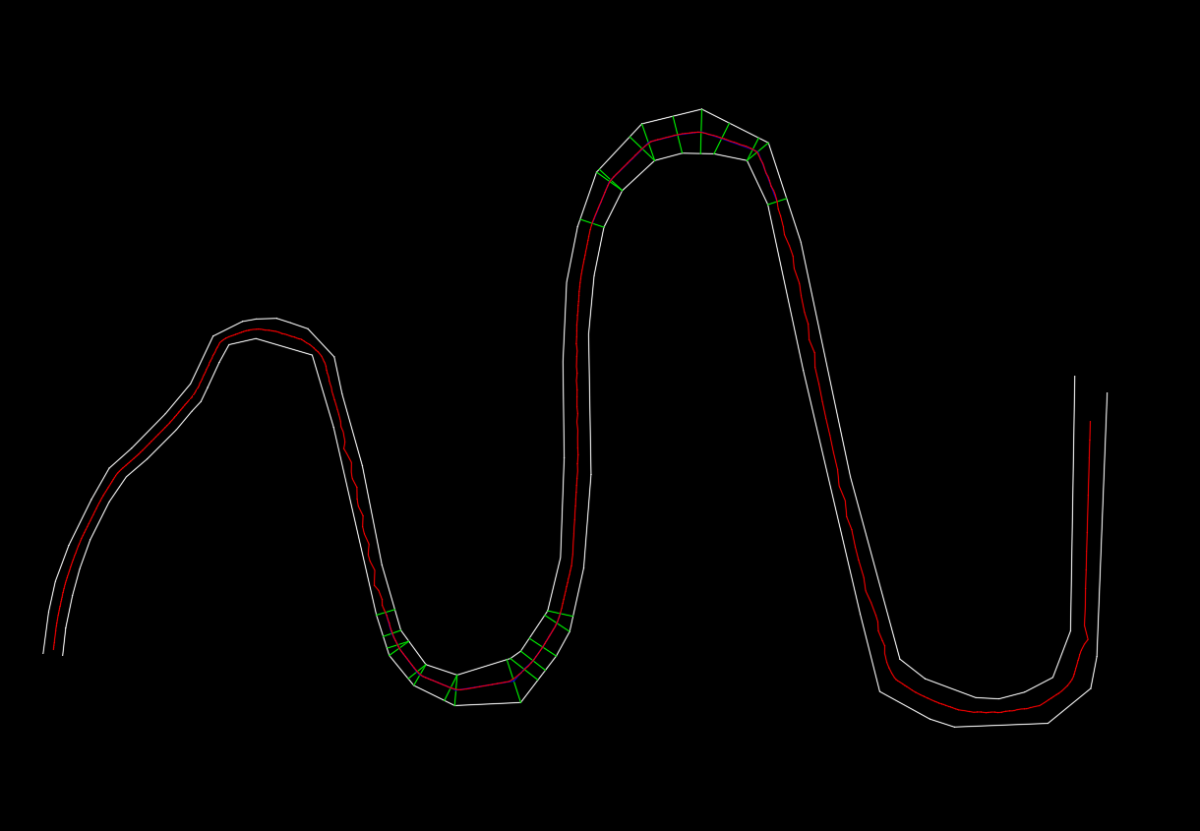
Pretty good, but still needs a lot of tweaking, it's really strange on the OPs AxisExample drawing. Looks very promising for a top notch solution, IMO. Good work.
-
In the future please use Code Tags for your code. (<> in the editor toolbar)
-

Optimizing Workflow with Loop Controls and Data Management
Steven P replied to maahee's topic in AutoLISP, Visual LISP & DCL
Reading about selection sets yesterday, if you are deleting from a selection set within your code, be aware that the entire set is indexed again which can add in delays (set contains entities 1 2 3 4 5 6 78 9, delete entity 5 from the set, then 6 7 8 and 9 are all indexed again to be 5 6 7 8 - time which can add up with very large selection sets). For case 1 I would be considering what you are doing in ';;;;code' to see if there are efficiencies in there (try running it as you write above to get a benchmark for the speed over your large selection set without any other codes) -
 faza joined the community
 -
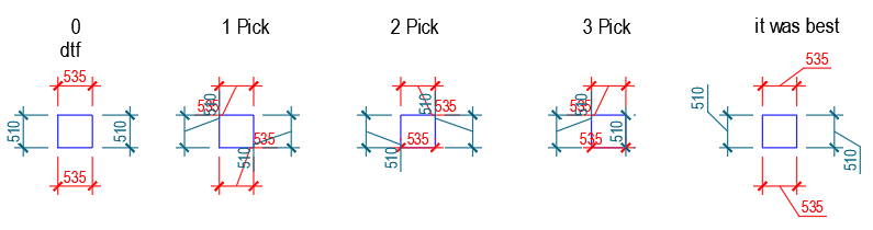
I've tested the code. In this way, it is difficult to guess the desired position of the dim text. Then you have to manually correct the position of the dim text. I'm using a macro *^C^C_aidimtextmove;1;\; to move dim text with an indication of position. You can write this macro as code, but the command works once with one size, I can't add a loop to change multiple sizes in one command call. (vl-load-com) (defun C:dimtxtmove (/ ) (vl-cmdf "_aidimtextmove" "1") (vl-cmdf pause) (vl-cmdf "") (princ) )
-
Your code looks brilliant, but for some reason I can’t get it to work. Is it possible I’m doing something wrong?
-
Yeah didn't think this would be so difficult. posting what I have so far. but I think ill stop here as this code is just for testing and only leaves points and not a drawing a continuous polyline. mid.mp4 -edit would notice that line types would stop the code for some reason so hard coded continuous. or maybe just my ganky code. midpoints.lsp
-
(defun c:dtf (/ *error* ent obj entg dimsc but counter) (princ "\n Move DIM Text to Various Points..") ;; https://www.cadtutor.net/forum/topic/97280-toggle-dimension-lisp/#findComment-666274 (defun *error* ( msg ) (setvar 'cmdecho 0) ;; 5.28.24 (vla-endundomark (vla-get-activedocument (vlax-get-acad-object))) (if msg (prompt (strcat "\n" msg))) (setvar 'cmdecho 1) (princ) ) (defun dotx (/) (princ "\n ** Reset **..") (command "dimoverride" "c" ent "") (command "dim1" "hometext" ent "") ) (defun dotl (/) (setq tpos (mapcar '+ (cdr (assoc 13 entg)) (list 0 dimsc 0.0))) ;; (vlax-put obj 'TextMovement 1) (vlax-put obj 'TextPosition tpos) ) (defun dotr (/) (setq tpos (mapcar '+ (cdr (assoc 14 entg)) (list 0.5 dimsc 0.0))) (vlax-put obj 'TextMovement 1) (vlax-put obj 'TextPosition tpos) ) (defun dobl (/) (setq tpos (mapcar '+ (cdr (assoc 13 entg)) (list 0.0 (- dimsc) 0.0))) (vlax-put obj 'TextMovement 1) (vlax-put obj 'TextPosition tpos) ) (defun dobr (/) (setq tpos (mapcar '+ (cdr (assoc 14 entg)) (list 0.0 (- dimsc) 0.0))) (vlax-put obj 'TextMovement 1) (vlax-put obj 'TextPosition tpos) ) (setvar 'cmdecho 0) (setq counter 2) (while (setq ent (car (entsel "\n Pick DIM: "))) (setq entg (entget ent)) (setq obj (vlax-ename->vla-object ent)) (setq dimsc (vlax-get obj 'scalefactor)) (if (= but nil) (setq but 1)) (cond ((= counter 1) (dotl)) ((= counter 2) (dotr)) ((= counter 3) (dobl)) ((= counter 4) (dobr)) ((= counter 5) (dotx)) ) (setq counter (+ counter 1)) (if (= counter 6) (setq counter 1)) ) (setvar 'cmdecho 1) (*error* nil) (princ) )
-
This gets the current styles (if (not ah:vercheck)(load "vercheck")) (ah:vercheck) ; version check see vercheck.lsp (setq lst '()) (vlax-for j (vlax-get *AeccDoc* 'SurfaceS) (setq lst (cons (cons (vla-get-name j) j) lst)) ) (princ lst) It should be possible to make a single new style using the data from an existing style. I need to dump say a few of the styles to see what is in them. It will take a little while as have to go elsewhere to work on CIV3D. Then use a VLA-add a style. Similar to add description keys. Just a side comment we had a survey dwg form other software so rather than import the styles we just copied all of the other dwg into our company DWT, so everything was set up correct. The dwg had 3faces so we could make a TIN. Sounds easier way. vercheck.lsp
- Yesterday
-
Getting inside the CIV3D database can be difficult. Its not a straight forward task to just get this item out of a CIV3D dwg. I did a few tasks re CIV3D and often have to look at different spots in the data base than what you would think hold the information your after. One thing I did was a IMPORT Description key sets, as you could only export. I did some other stuff with surface styles, I have a toolbar that allows you to set the current surface style without using Toolspace set contour interval, on/off etc. In Civ3D depending on version there is sample code for making different CIV3D objects like import points, make a surface style, I have limited access to CIV3D but the sample code is a few levels deep in the CIV3D directory, they have lisp and .NET examples. I think in later releases they removed some of the sample code. I will see if I can find something. Have a look at this. https://www.google.com/search?q=get+alignment+style+detials+civ3d+autolisp&rlz=1C1CHBF_enAU856AU856&oq=get+alignment+style+detials+civ3d+autolisp&gs_lcrp=EgZjaHJvbWUyBggAEEUYOTIJCAEQIRgKGKABMgcIAhAhGI8CMgcIAxAhGI8C0gEKMTcxMDRqMGoxNagCCLACAfEFrEvci61nuFXxBaxL3IutZ7hV&sourceid=chrome&ie=UTF-8
-
 Lana_ joined the community
 -

Optimizing Workflow with Loop Controls and Data Management
mhupp replied to maahee's topic in AutoLISP, Visual LISP & DCL
You can limit what ssget selects by entity, layer, color, size, basically anything in dxf codes. please read up on ssget This means you could just make a window selection. And not have to zoom in and out to make selections. also @Steven P already said "ssadd does a check if the entity exists in the set" check the length of SS before and after to see if it was already in the list. also also looks like your not using localized variables could be why its taking so long. (defun C:123 ( / ss pick l) (setq ss (ssadd)) (princ "\nSelect Entity: ") (while (setq pick (ssget)) (foreach ent (vl-remove-if 'listp (mapcar 'cadr (ssnamex pick))) (setq l (sslength ss)) ; Length before adding (setq ss (ssadd ent ss)) ; Try adding entity (if (= l (sslength ss)) ; If length is the same, item was already in list (princ "\n\nDuplicate Selected Line") ) ) (princ (strcat "\n" (itoa (sslength ss)) " Entities now in Selection SS")) ) ; rest of code goes here (princ) ) (defun C:bm ( / ss ent) (while (setq SS (ssget (ssget "_+.:E:S"))) ;exits if selection isn't made (setq ent (ssname ss 0)) ;CODE ) ) -
Is it possible to import surface styles from my template using lisp? I asked Claude and the lisp provided inserts all object styles. ;;-------------------------=={ Import Alignment Styles }==---------------;; ;; ;; ;; Imports Alignment Styles from Power Generation template ;; ;; Uses INSERT method to import block with embedded styles ;; ;; ;; ;;----------------------------------------------------------------------;; (defun C:PG-INS-ALIGN ( / template_dwg curecho curlayer block_name *error*) ;; Error handler (defun *error* (msg) (if curecho (setvar "CMDECHO" curecho)) (if curlayer (setvar "CLAYER" curlayer)) (if (not (member msg '("Function cancelled" "quit / exit abort"))) (princ (strcat "\nError: " msg)) ) (princ) ) ;; Save current settings (setq curecho (getvar "CMDECHO")) (setq curlayer (getvar "CLAYER")) (setvar "CMDECHO" 0) ;; Set template path and block name (setq template_dwg "C:/WSB-DT/Autodesk/Power Generation/Templates/Utility Scale Solar/RENEWABLES-CT-DESIGN.dwt") (setq block_name "TPLT-Alignment-Styles") ;; Check if template file exists (if (findfile template_dwg) (progn (princ "\n----------\nImporting Alignment Styles...") ;; Set layer to 0 (setvar "CLAYER" "0") ;; Insert block from template ;; Format: blockname=filepath (command "_.INSERT" (strcat block_name "=" template_dwg) "0,0,0" ; Insertion point "" ; X scale (default) "" ; Y scale (default) "") ; Rotation (default) ;; Check if insert was successful (if (entlast) (progn ;; Explode the inserted block (command "_.EXPLODE" (entlast)) ;; Purge the block definition (command "._-PURGE" "_B" block_name "_N") ;; Run audit to verify drawing integrity (command "._AUDIT" "_Y") (princ "\n----------\nPower Generation Alignment Styles Have Been Imported!") ) (progn (princ "\n----------\nERROR: Block insertion failed!") (princ (strcat "\nBlock '" block_name "' not found in template")) (princ "\n----------") ) ) ;; Restore settings (setvar "CLAYER" curlayer) (setvar "CMDECHO" curecho) ) (progn ;; Template file not found (setvar "CMDECHO" curecho) (princ "\n----------\nERROR: Template file not found!") (princ (strcat "\nLooking for: " template_dwg)) (princ "\nPlease verify the path is correct") (princ "\n----------") ) ) (princ) ) ;;----------------------------------------------------------------------;; ;; Load Confirmation ;; ;;----------------------------------------------------------------------;; (princ "\n----------") (princ "\nAlignment Style Import Command Loaded:") (princ "\n PG-INS-ALIGN - Import Alignment Styles") (princ "\n") (princ "\nNote: Template must contain a block named 'TPLT-Alignment-Styles'") (princ "\n with embedded alignment style definitions") (princ "\n----------") (princ)
-
 david.o joined the community
 -
 Tamsan joined the community
 -
@Marko Ribar has a Travelling Salesman here at CADTutor. TSP.ZIP (Travelling Salesman Problem) - AutoLISP - Programs and Scripts - AutoCAD Forums I was just thinking of the relationship of this to the Travelling Salesman. One of the examples I ran across was similar to @GLAVCVS recess example, as well as the problem of a river that splits around an island or branches ( even a road, ROW, etc.). Even GIS tools need pre and post work and have conditions... Polygon To Centerline (Topographic Production)—ArcGIS Pro | Documentation I think I see why my daughters coworkers use CAD to do the center lines, I am guessing as haven't heard back on details, but I wouldn't be surprised if they used Gian's LISP or similar or just do manually like lrm's demonstration. I also saw an example of that on Bentley MicroStation forums. You may have seen a recurring tool on the GIS forums, etc. called v.centerline. v.centerline - GRASS GIS manual -A link to the source code is at the bottom.
-
Scott, This works with one problem. I hope you can fix it. The leader line becomes to long when selecting the dimension to relocate. If it could stayat the original length, this would be awesome. Thank you for your efforts.
-
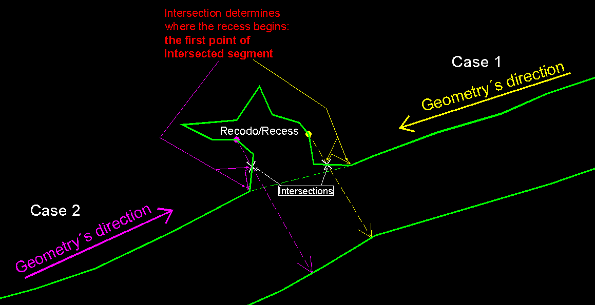
Everything SLW210 has researched is very interesting. I had no idea this had been such a thoroughly discussed topic — and with such limited success. I guess that makes it even more interesting. In my opinion, it is possible to obtain a center polyline that is equidistant from both edges. But two conditions must be met: 1. The user must ensure that the geometry of both edges is correct: they must be 2D polylines with no repeated points and no geometric inconsistencies of any kind. And, in principle, to avoid extending the search for a solution, these polylines should not contain arcs. 2. One must accept that any edge containing “recesses” (“recodos”) must be handled using auxiliary axes. What is a recess? It is a geometric setback, in any direction, along one of the edges. For example: if you advance segment by segment along an edge (in either direction), the start of a recess would be defined as any vertex from which the shortest distance to the opposite edge forces the projection to intersect its own edge. My conclusion: for edges without recesses, I believe it is possible to find an equidistant centerline or axis. And for edges with recesses, although considerably more code will be needed, they should be solvable using auxiliary axes. I hope to have code soon that supports all of this.
-
I think ronjonp posted something that if you clicked two points on a polyline it would find the shortest path. (traveling salesman) The method I was working on but haven't finished. two open polylines find start and end points of each test how they are oriented and revers one to use to make a closed polyline find the longest distance between the two original polyline divide that by like 500 and offset in using entlast and eventually will end (cant offset anymore) find the polyline with the lowest area but still has the same amount of vertex as the original boundary. using that smaller boundary to draw vector lines between smallest and original boundary. (where im at now) take all other polylines inside smallest and add them to a point list. remove any points that are Collinear with any of the drawn vector lines. this should leave only the points on the center line. starting at one end need to start group points that are Collinear to each other. of those points entmake a line on the farthest distance. these lines are incomplete segments or might not be touching and will need to be extended to each other or the vector lines or both. problem i am finding/trying to solve what slw210 pointed out about if two segments are close to being parallel points wont be found. need three points to calculate collinear working over a group of points to split out each segment.
-
I just use the QGIS Import for drawings from AutoCAD and I get the layers. I think for surfaces, QGIS needs DEM, IIRC _SurfaceExportToDem is in Civil 3D. Maybe in QGIS Import the SHP or just the .dwg and Go to "Layer" then "Add Layer" then "Add Vector Layer". My QGIS is at home, so I think those steps are close.
-
The "removeDuplicates" function is missing.
-
Hi all, I get a DWG with multiple layers with lines and such. Now... each line has Object Data linked to it. I need to make a export to GIS, where each layer is its own layer in QGIS. When i make a export to SHP or GML, and load it in QGIS, all layer informatie is gone and is put on only GIS layer. What is the most effective way to export AutoCAD layers to GIS layers?
-
I have been trying to explain the issues to the OP to no avail. From what I gather from my daughter, her coworker does the centerlines in CAD not ArcGIS, then imports them. From what I gather, CAD is better for tweaking a more accurate line manually after running a LISP or other program. Which is apparently what some if not most of the surveyors, geologist, map/civil, etc. are doing no matter the GIS software or CAD software. Getting it close with a tool then tweaking it if needed, or probably if just a one time deal completely manually. I have a couple of new LISPs, I left one of them to draw a different centerline depending on which polyline is picked first, between the two centerlines, one goes close to perfect through the right curves, the other close to perfect through the left curves on the OPs AxisExample.dwg. As I posted, a Voronoi is what most of the tools use, apparently they can get off center as well, but generally work the best. The other option is to go LRM's method or along the lines of Jeffery P. Sanders rolling ball, but the rolling ball can take a while it seems to if looking for accuracy. Daniel's Python method would probably be the best IMO. I still plan on seeing QGIS results when I get the time.
-
Does it not create a polyline for you? I did post it without the 'animation' if that is what you mean.
-
Is it possible that your attached code is incomplete?
-
I copied another function of dijkstra's algorithm to find the shortest path. It might need a lot of optimization, but just as a proof of concept. centerline voronoi dijkstra.lsp Code I forgot to include: (defun RemoveDuplicatesAux ( x ) (cond ((vl-position x index)) ((null (setq index (cons x index)))) ) ) (defun RemoveDuplicates ( lst / index ) (vl-remove-if 'RemoveDuplicatesAux lst ) )
-
 ivv joined the community
 -
Using a voronoi diagram (code by ymg, ElpanovEvgeniy and Marko Ribar) You can get some very good reference points. Just have to find a way to get rid of all the 'branches' and then take al the midpoints of every line to get a good centerline. centerline-voronoi.lsp