Search the Community
Showing results for tags 'autocad'.
-
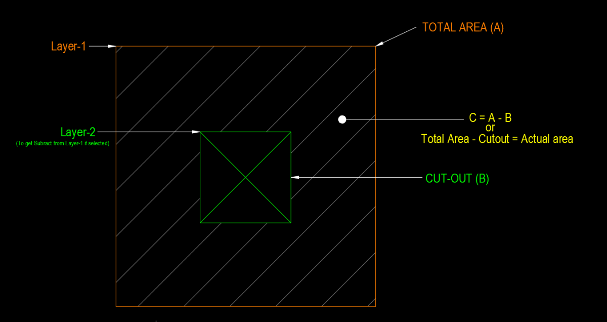
Hi Everyone, From few days I'm trying to make an auto lisp which can understand the difference between 2 different layers and calculate area according to that. Unfortunately I'm not getting proper results anyone can please help. I was trying to create the lisp in below steps. Step-1: After entering command user will select whole drawing in single selection Step-2: Lisp will select only object in Layer-1 & Layer-2 (Other layers objects will be ignored) Step-3: Lisp will calculated the area of Layer-1 & Layer-2 Step-4: Now it will Subtract the area of Layer-2 from Layer-1 Step-5: and paste it as Text.

-

LISP INCREASE INTERNAL CONSECUTIVELY IN BLOCK FROM OD
BRIAM RAMON posted a topic in AutoLISP, Visual LISP & DCL
Hi! With the help of the autodesk forum I have this lisp that consecutively increments a numeric value in a specific field of OD, also copies the block name to another field of the same OD. This lisp assigns the internal consecutively when the field INTERNO_SENAL has a data type of character, can the same process be done when the type of the OD field is as internal? Having this lisp is it possible that the value of INTERNO_SENAL is also copied in the INTERNO attribute of the block? ADD_ID.lsp -
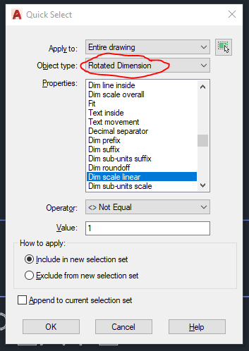
Hello, I was wondering if anyone has/ can whip up a LISP routine that selects any dimension (rotated, aligned, diametric, radial, ect) from the entire drawing (not just a selection) that has a "dim scale linear" value that is <> Not Equal to 1 I have been doing it in "qselect" then choosing the options but this is very time consuming. (Where it says "Rotated Dimension" I would like the command to check all dimension types at once, not just rotated) Thank-you kindly, Ola
-

create dropdown menu in autocad to select commands
Manuel_Kunde posted a topic in AutoLISP, Visual LISP & DCL
Hi all, I am trying to write a lisp that will create a DropDown list in Autocad. With the selection from the fields I want to execute different commands that I have defined before. (defun c:create_dropdown () (setq choise1 command1) (setq choise2 command2) (setq choise3 command3) (setq choise4 command4) (strcase (initget (getkword [choise1/choise2/choise3/choise4])))) ) -
How to transfer Link Template Data to Object Data - AutoCAD MAP 3D
BRIAM RAMON posted a topic in AutoLISP, Visual LISP & DCL
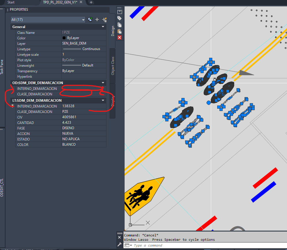
Hello Community! I have been researching this for some time, I am trying to know if it is possible through a routine (lisp) to transfer / copy the information from LT (link template associated with a database in access) to the OD (object data) as I show in the image. So i need a very specific Lisp/VLisp/VBA/Dotnet routine who asks for : -- The Link Template DB name -- Which DB fields are you interested for -- Which OD Table MAP to fill -- Which OD Fields MAP to create or to use (if already existing) -- Selecting objects -- Retain only objects which the correct parameters -- ACTION ... Copy Data to OD fields ... append DWG & MDB files as example. thanks for the help you can give me, greetings EJEMPLO.zip
-
I have received the attached drawing from one of my clients. (I have removed geometry to maintain confidentiality. But it retains the essence of problem that I have). I have to write VB/A program that extracts data from this drawing. For that I need to know the extents of the drawing. The system variable ExtMin shows a value of X (98331) which is greater than the X (92817) of min. point (left bottom corner of the border) of existing geometry. I have tried everything (purge, overkill, audit, recover) but can't find a way to correct the value of ExtMin. Assuming that this drawing is corrupt and can't be recovered, then I have another problem. How can I programatically find that the ExtMin value of this drawing is wrong and hence this drawing is corrupt. ExtMin Problem.dwg
-

automation How to create random but "inline" stipple line or hatch pattern
pseudoclay posted a topic in AutoCAD 2D Drafting, Object Properties & Interface
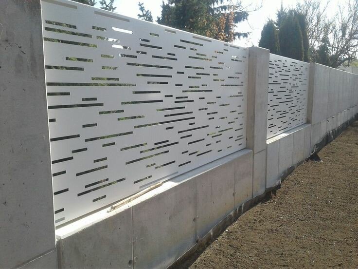
Good Day AllI've turned to forum advice and I really hope someone can help me.I have to create 13 wall panels that will be laser cut. The panel drawings were done in Inventor and I'm editing the flat pattern in AutoCAD. If you look at the attached images of one of these panels you will get the idea, each panel cut-out "pattern" must be randomly generated and I was hoping someone could give me some advice as doing this manually, by hand, is insane and after all we work on machines and machines can automate right!? I am also attaching a flat pattern of one of the panels (they all have different height and width dimensions too). Just as a side note I did try a scatter script but it doesn't give the appropriate result because if you look closely you will see the dashes are inline but randomly knocked out. I was thinking maybe a random dashed line script or procedure that can then be exploded to rectangular shapes for DXF export or a custom random hatch but I don't know how to do either. Hope I'm making sense. Thank you in advance.
-
Hello, I am new in AutoCAD. I draw 1:1 floor plan, I draw 1m in real like 1 in autocad. Now I have to plot it in pdf as 1:50. How can I do that
-
Hello! I have been getting suggestions and help from this forum for some time now, but have reached a point where I am currently at a loss. I am still relatively new to the topic of lisp and co, but I am trying to improve constantly. For my current problem, I am trying to select a block and insert a point into it. I have simplified my current lisp file into the function below so as not to go over the top. My problem is that I get back an empty selection set and thus can't execute the function from Lee Mac correctly. (defun TestFunction ( / ) (while (= ss NIL) (if (setq ss (ssget "_+.:S:E:L" '((0 . "INSERT")))) (progn (setq ent (ssname ss 0)) (setq Block (vla-item (vla-get-blocks (setq doc (vla-get-ActiveDocument (vlax-get-acad-object)))) (cdr (assoc 2 (entget (ssname ss 0)))))) (Insert_Point) ) ) ) ) (defun Insert_Point ( / ) ;; Block Einfügepunkt ermitteln (setq Message (strcat "\nEinfügepunkt wählen:")) (setq Pnt (getpoint Message)) (setq sel (ssadd)) (setq Point (vla-addpoint Block (vlax-3d-point Pnt))) (ssAdd (vlax-vla-object->ename Point) sel) ;; sel stays empty so the following line cant be executed properly (UpdateBlock doc ent sel) ) Many thanks for your help! Best regards Florian
-
Hi I work in a company, people come to us with their plot registry, on which are the dimensions (north,east,south,west) and area of their plots. But there are no angles. For example, a plot of 25 * 10 meters with an area (according to the mathematical calculations) should be 250 square meters. But 244.95 is listed on the registry.My question is how do I quickly draw this plot (according to the registry) in AutoCAD? Is there any lisp for this?
-
Hello! I need some advice on AutoCAD! The question is: our organization has moved back to remote work. What version of the program would you recommend to install on a laptop, taking into account that we need to use 5 computers simultaneously with "WorkTime" and "Zoom".
-

block insertion point and Block attribute value
Kubucama posted a topic in AutoLISP, Visual LISP & DCL
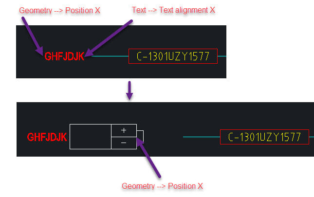
Hello everyone, The attached code that "Replace the text by block and transfer the value to the attribute" and the code is working. What I intend to do now and am not succeeding in doing is the following : 1) I noticed that, the block insertion point is being at the coordinate (Geometry --> Position X of variable T2B_Text). Is it possible to insert the block at the coordinate ( Text --> Text alignment X of variable T2B_Text)? (See image 1) 2) Is there any way to make sure that the total value of the variable "T2B_AttributeTag" is not all transferred to the block attribute? (See image 2) Example: T2B_AttributeTag = TO 1301-UZY-1826A Value of Block attribute (T2B_Block) = 1301-UZY-1826A (Accurate this way) Obs : The Txt file is by (DannyNL), taken from the AutoCad forum. Code Lisp.txt
-

autocad architecture Projecting generated sections to lines
Bojan posted a topic in Architecture & ADT
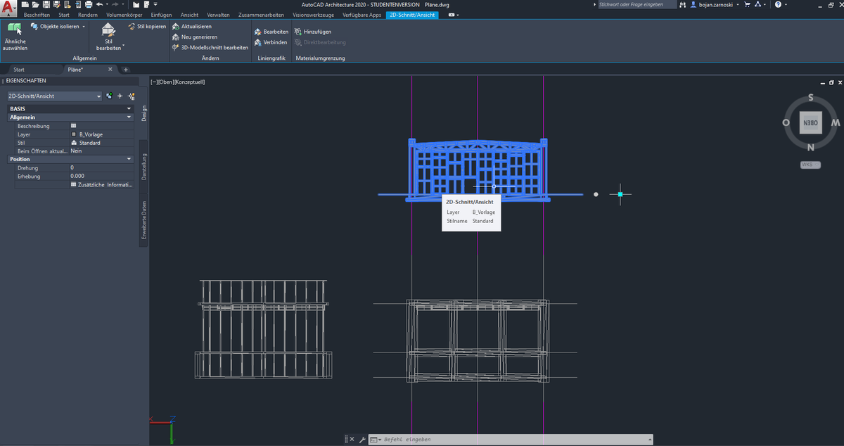
Hello fellow Autocad users, I've recently recieved a messy 3d model (consisting of various geometry types) in order to draw section plans from them. First I tried to generate a floorplan with Autocads "Generate Section/Elevation" tool, thus recieving the projection as intelligent object. In order to draw the plans cleanly from the messy projection I want to transform the projection into a linegrafic, but I can't find a way to edit the projections without crashing Autocad. I also can't use flatshot since the projection is not a Brep. Is there any way to transform the projection into a line grafik, or another alternative to generate cross sections? I've attached an image to depict the problem (I use a german version of AutoCad architecture 2020). Thank you in advance!
-

Electric Transmission poles
Shablab posted a topic in AutoCAD 2D Drafting, Object Properties & Interface
Are there any resources I can take a look at to find all different types of electric transmission poles in autocad. -

Create slope with lisp Polyline (WANT TO ENHANCE)
Prageeth posted a topic in AutoLISP, Visual LISP & DCL
I Have lisp for placing slope and arrow with polyline and i want enhance this to what i need mention in my drawing file..so i have attached lisp & sample drawing file . and also want to enhance lisp for select all polyline at once, currently lisp select on object at once. thanks. Slope.lsp SLOPE SAMPLE.dwg -
I found valuable lisp for auto creation block. I want to improve this lisp to following requirement * block selected object individually, not in one block thanks AUTO-BLOCK.LSP
-
Can anyone help me for the create lisp for following condition . * I have 200 of text separately in my drawing ..i want block them individually each one. *i want select 200 of text at once block them individually .. Can any one create lisp for that.thank
-
Not sure what i have been missing here. But finally decided to do something about our custom code. The lisp looks for a file and if present on system proceeds to step 2. Step 2 it checks for match with path. this is where i get confused.. I thought a (princ) close's the file clean (no loose ends) however the settings are there (in the options) but not applied. what am I missing? I have looked for some way to apply settings under the options dialog but no success. (Setvar "cmdecho" 0) (if (= "24.0s (LMS Tech)" (getvar "ACADVER")) (progn (if (not (wcmatch (getenv "PrinterConfigDir") "*path*")) ;Looking for Printer Configuration Search Path (setenv "PrinterConfigDir" "path") ;If not found add Printer Configuration Search Path ) (if (not (wcmatch (getenv "PrinterDescDir") "*path*")) (setenv "PrinterDescDir" "path") ;If not found add Printer Description Search Path ) (if (not (wcmatch (getenv "PrinterStyleSheetDir") "*path*")) ;Looking for Path in Plot Style Table Search Path (setenv "PrinterStyleSheetDir" "path;") ;If not found add Plot Style Table Search Path ) ) ) ;(alert "message") (Setvar "cmdecho" 1) (princ)
-
I can convert my raw AutoLISP (.lsp) codes into Visual Lisp (.VLX) and .FAS application using AutoCAD VLISP IDE. I was looking into Autodesk App Store and downloaded some of the free applications. It was .msi. That means it will install directly on Windows and link-up with installed AutoCAD. I am very new in the App Store. Could you please help me to understand to convert my .lsp or .vlx or .fas into .msi? Thanks.
-
Hi, I'm having a hard time figuring out how to make a toolbar that can be downloaded for all to use. My problem is how do you share a "common directory" with the world? The toolbar works perfectly fine on my computer, because I have defined my own directory in the macro under the cui command. So the question is: how do you make a "common directory" so that the toolbar can be accessed on any computer? I hope I have made myself clear. Thanks!
-
Hi all, does anyone know how it is possible to be a tester of beta (and alpha) versions of AutoCAD and Revit and other Autodesk products? I appreciate any help!
-

Where can I send wishlist to Autodesk?
Ahankhah posted a topic in AutoCAD Bugs, Error Messages & Quirks
Hello everybobdy, is it possible to let me know how I can send Autodesk my wishlist about AutoCAD and Revit and other Autodesk packages? I appreciate any help! -
Hi All, anyone knows when AutoCAD 2021 will be available?
-
Hello Everyone, I'm working on a GIS Application which is running with AutoCAD, in that we are placing some lines and structures, while placing that the annotation will be placced automatically middle point of that poly line. after that we need to align that as per the below image. is there any possible to align the blocks automatically. steps would be Select two Blocks--->Select the Line then the blocks should be alined automatically as per the below image. can anyone help me on this. Thanks in advance. Sample.dwg
-
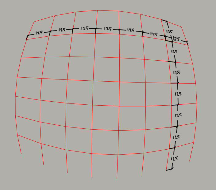
Hi guys, I have 3d polyline net system as you can see down below, trying to measure every cell automatically (see attachment), problem is that net is 3 dimensional and hard to define measuring angular, every 3d polyline is individual (see attachment) just want to select the 3d polyline and giving measures between nodes, do anyone know how to solve this puzzle an easiest way? Best Regards