Search the Community
Showing results for tags 'block'.
-

Using Constraints and Stretching Commands in Dynamic Block
numberOCD posted a topic in AutoCAD 2D Drafting, Object Properties & Interface
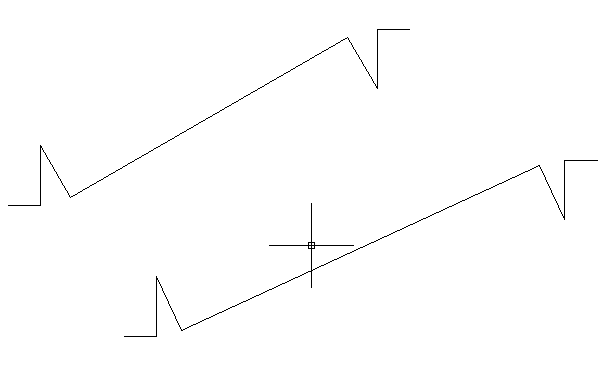
Hi all, I was trying last week to make a dynamic block and my technique got too complicated. So I'm trying to figure out a base stencil with 3 Polylines where the first and third are identical but 180 degree rotation where the first is stationary and the third one moves. Then I want a second polyline that connects between the first and third that stretches, but keeps two perpendicular angles. The image below shows a before and after. Does anyone have any tips of how I can use Constraints with the activities to keep all line segments a constant length besides the the long diagonal in the middle? All help appreciated! Constrained_Stretch.dwg
-

Cad blocks mysteriously say invalid?! Help?!
tmelancon posted a topic in AutoCAD Drawing Management & Output
Our server went down today and unfortunately our Master AutoCad "working" file folder did as well. We were able to get it restored however all of our blocks that we actively use for toolbars, drop down menus, or thru insert command are all saying invalid file. I am still stumped as to how this happened and am only seeking possible advice to get quite a few blocks and stuff I created over the last 3 days and for educational purposes. I do in fact backup all of our blocks every now and again but these newbies were created within a day or so ago so they werent backed up. I tried running recover, nothing. We are back up and running with my backup copy I just saved the old copy as "OLD" for testing purposes and to see if I can find a solution. Any advice and discussion helps. Thanks -

Selecting Individual Layers Within XRefs
SJC2014 posted a topic in AutoCAD Drawing Management & Output
Hello, I'm a fairly new AutoCAD user (AutoCAD 2012 version) so there's probably a very simple answer to this. I have a "Master" drawing with one xref inside. Im producing drawings (layouts) from this master dwg file. Im trying to freeze individual layers within the xref, I can do this by using the Layer properties manager "VP freeze" column, this is very slow. What I would like to do is select an individual layer of the xref within the viewport and freeze it using the layer dropdown list at the top, however when I click one of the layers within the xref all the layers within the xref become selected. How can I select individual layers within the xref????? Thanks -

Mirrored annotative dynamic block flips back after re-open
PetterVitestam posted a topic in AutoCAD Drawing Management & Output
Hi! I've been experimenting a bit with annotative dynamic blocks, specifically with the purpose of creating annotative section arrows. I've created an annotative block containing the arrow drawing and a single attribute definition for the lettering (A, B, C...) that does NOT have locked position so that the user can be able to move the letters. Everything works as expected except one thing: when testing I've been mirroring the block to get one section arrow at each side of the plan. The text even stays correctly orientated (and if the section is diagonal I can go into the enhanced attribute editor and specify the text rotation). The problem occurs when I save and re-open the drawing, then it seems that AutoCAD forgot that the block was mirrored, and it has been flipped back and moved around. I am pretty sure this doesn't have anything to do with Annoreset or some variable like that, but I'm not sure. I was wondering if anybody else had a similar issue or can recreate the problem. I'm guessing this is just one of those AutoCAD things... and that the solution would be to create one block for each side, and don't ever mirror them. Rotating and scaling the blocks work just fine. Thanks in advance. I'll attach my file. section arrow.zip -
Hi! I'm looking for a script that does this: insert block from specific (non changing) folder, *type in name of block* no rotation no scaling insert to picked point on screen (meaning- i only want to type the name end pick a point of insertion) any ideas? thanks a lot!
-
Hi all, I'm currently using AutoCAD 2014. I'm use to using AutoCAD but have never used VBA or AutoLISP before. Really just found out about them from doing some research on the internet and hoping for some help with my dilemma. I have a floor plan already drawn and each individual room already has a separate hatch created as a block with a unique identifier. What I would like to be able to do is somehow make the layer of the block change to represent the percent completion of each room. I would ideally like to just be able to make an Excel spreadsheet that contains in column A the block title like Kitchen, Bath Room 1, Living Room, etc. and column B would contain the layer I want to move it to. So when I change column B from 20 to 30 the layer updates automatically. A couple different people will be inputting to the spreadsheet which is why I want it to be able to the update automatically when needed. My floor plan contains about 60 different spaces (blocks) and has about 10 different colors (layers) to represent the percent completes. I'm not really sure how to go about this but I'm very much willing to learn. Eventually the drawing will grow to have over 300 individual blocks and around 12 layers. So you can see the amount of effort it would save versus selecting each block and changing it's layer individually. Thanks, JMB
-

What is the difference between BLOCK & INSERT?
shailujp posted a topic in AutoLISP, Visual LISP & DCL
I see sometimes INSERT is used in SSGET and sometimes BLOCK to capture the blocks. Whats the difference between two and any specific application it requires to be used? Please guide. -

Wants to select the same block having exactly same dimensions?
tipu_sultane posted a topic in AutoCAD 2D Drafting, Object Properties & Interface
I got a some type of network and wants to count the block having the exactly same dimensions. This is because to make their division with respect to length. Example say there is total 27 number of blocks having the length 7 meter etc. But I am facing the problems, when I select the blocks, all have been selected. Find below the attached images of my method which I apply. I just first used the explode command then select the block select similar object and move to somewhere else. I need some help to solve this problem. I have used the command like list and area but I believe its time consuming and hope there is a simpler method to do this job.
-

Redefining a block via a custom marco button
mrgrotey posted a topic in The CUI, Hatches, Linetypes, Scripts & Macros
Hi guys, long time no post. I have a LOT of drawings all with the same block in and I have updated the block so therefore want to redefine all the blocks, ...as you do. I only have autocad LT 2010 so havent got the LISP coding option. I am trying to do it by assigning the following example code to a button and running it. The only problem is it doesn't run it properly... block name for example is 'box' C^C^_-insert;box=C:\users\michael\desktop\box.dwg;y;C^C^ All the individual lines work when typed but when used in the button macro it stops at: C^C^_-insert;box=C: ...and doesnt accept the backslash and so stops the macro from continuing. How can I get it to run a file path??? this is doing my swede in -
Hi there, So my job would like me to create a usable library of products to make things easier. We make custom cabinetry, but there are many more standard sizes that may be useful. I'm vaguely familiar with creating blocks and saving, but I'm trying to find out if there is a good way to go about making this library since the sizes will need to be changed often. Is it even worth creating such a library? Is there an easy way to temporarily edit blocks to make them a few inches bigger or smaller? I've been using AutoCAD technically for years, but it's been very on and off, and I learned on my own so I don't know all the correct ways to go about things. Help?
-
Hi to you all, i've been watching a lot of info on your site, now i decided to register myself. So here's my first issue. Been googleing and searching for quite a while now but i cant seem to find any solution. When i use Battman to re-arrange my attributes (in order to be able to auto-number them easily with a numbering-lisp), all values, rotation actions etc. are messed up and the block becomes unusable. I use 2009, I've also tried it in ACAD 2014, same story. Any ideas....cos the next step would be to create the block from scratch. thnx.
-
Hi guys, When I insert a dynamic block containing text attributes, it brings up a list of questions for me to fill in the information (as normal). For convenience, I would like them to appear in some sort of logical order. Does anyone know how this can be achieved? To rearrange the list?
-
Hi, I am trying to create a macro (or lisp) and am struggling to find how I would do it. Basically what I want to achieve is this: Click Custom button, Click first point (p1) Click second point (p2) Insert block at p1 and set scale to equal distance between p1 and p2 Set bearing to the bearing between p1 and p2 then end. The process will take 3 clicks including click the custom button. This is to basically speed up inserting doors. I was thinking possible making it draw a line when you click p1 and p2 then use this line to grab the start of line, end of line and bearing. Or using variables. Any help would be appreciated, or pointing in the right direction. I don't expect anyone to do all the work for me, just a hint would be awesome.
-

Batch Plot to PDF with Custom Filenames
churchill posted a topic in AutoCAD Drawing Management & Output
Here's a question for the jedi's. Any idea how I can do a batch plot to PDF whilst appending some element to the end of the filename? Using AutoCAD 2011's batch plot, or TrueView 2014's batch plot the default PDF filename when plotting to PDF appears to be: -.pdf Which is okay. But I want to append to that the revision of the layout (C1, C2, etc.) which I currently store in a title block as a block attribute value. Any ideas if there's a method for somehow pulling this out and including it after the filename such that I could end up with: --.pdf Any thoughts? We're currently trying to transition to using the Sheet Set Manager, is the above any easier to achieve using that? TIA. -

Skewing a Block Vertically/Horizontally
OrangeFu posted a topic in AutoCAD 2D Drafting, Object Properties & Interface
Hey folks! After an exhaustive search on the forums the closest thread similar to mine was this one, and it was never resolved So here's my question in Video Form... I find at least once every project I need to do something like this (skewing/forshortening). If I make a section view of a set design (cutting right through the stage), I'll do that by taking my set elevations and skewing them. SOLUTION FOUND EDDIT: Holy Balls, YOU GUYS ARE AMAZING. Behold: The solution, painstakingly outlined in VIDEO FORMAT, and annotated..?! Thank you all for sticking with me on this one. You make this community so welcoming and inviting. -
I am a little new to assigning attributes. My company had a block with two attibutes that I need to alter. When the block is inserted, it asks a quantity. The other attribute is titled location. I am told if needed, all these quantities can be totaled per drawing. It has a title of "location". Two things: Can someone explain how to replicate this action? And is there a way to show all properties of a field for an attribute? Thanks, Nobull
-

Z value referencing block
Al_H_C posted a topic in AutoCAD 2D Drafting, Object Properties & Interface
Hi, Does anybody know a way of creating a block attribute that will reference the z value of a separate 3d model (topographical survey) at a given point? I know the z value of the block itself can be listed as a simple block attribute but I need the reference to check for the z value of an unlinked model which will be inserted/ x-reffed beneath the block. Any ideas? Thanks Al -
How to fix Block thumbnail preview in dialog box of a custom program
shailujp posted a topic in AutoLISP, Visual LISP & DCL
I have made updates to an old library block (file) and saved my changes. We have a custom menu, custom program and dialog box shows all different blocks to choose from and I frequently use it. The inserted block shows updates correctly but wont change the thumbnail preview inside the dialog box. Its not an attribute block or a dynamic block. Is there anyway to resolve the preview issue? -

How to make an existing block annotative
Benjo posted a topic in AutoCAD 2D Drafting, Object Properties & Interface
Hi, I created an dynamic block few weeks ago and forgot to make it annotative. I try the ddchprop command, switch annotative to yes but it automatically immediately switch back to no. Could anyone help me with this please? -

Dynamic Block - Rotate/Stretch along a linear path.
dblclkmatt posted a topic in AutoCAD Drawing Management & Output
Hello CADtutor, First time post, long time reader. Huge fan. I tried to find this problem on the forum before posting, but had no luck. I am trying to have a dynamic block that will show the profile of a steel plate, detailing the angle of a bevel. Including the plate thickness, the land, gap and the actual angle of the bevel. I've gotten most of it figured out, but having a grip to SET the angle at a specific number, while maintaining the drawing's integrity is proving difficult. I have attached the block I have created so far (minus the previous attempts to rotate the beveled angle). BVL_detail.dwg The basepoint of the rotate parameter should be at the junction of the bevel & land. I need it to stay connected to the end point of the top-most flat line as it rotates, which means the lines need to stretch to match the changing angle. It will either rotate that line along with it, or if I apply a stretch tool, it gets all disconnected and just plain wrong. One of the things I am liking about my current set up is I can grab a grip, and then type the number I need and it will pop on into place. Was hoping for the same effect if I typed in the angle, it would be exactly that, while also adjusting the drawing. I'm hoping to get some direction of things to try, or a straight solution. I've been tweaking with it for the better part of the day and finally conceded to ask for help. Even alternate solutions would be greatly appreciated. My first attempt was to have prompts that ask me for the details, and after I answered them all, it would just makes the detail for me. But that's some super secret CAD magic I just don't possess yet. If clarification is needed at all, please let me know. Thanks in advance! -
I am trying to simplify my companies current process of updating BOM. We currently type all part dimensions in an excel spread sheet to get the weight of different group of materials. I wanted to make a lisp that after changing one or many of the dimensions in the BOM blocks it would recalculate the weight, avoiding any typo errors when manually recalculating. Ideally it would compare the item number (eg "37014") and then multiply the 2 dimensions and quantity. Then add all of items and put the total in the bottom right block of that group (eg "753.5") I am not sure how to start this lisp any help will be greatly appreciated. all the blocks are called "97bill" and the attributes are "bubbleno" "qty" "material" "itemnumber" "total-units". Thanks
-

AutoLISP to read an attribute (diameter) to draw a circle?
linktf posted a topic in AutoLISP, Visual LISP & DCL
Can a AutoLISP command be written to read an attribute in a block and draw a circle with the attribute as the diameter using variables? The appilcation is taking the diameter of a tree trunk (the attribute), multipling by 12, and drawing the canopy circle on hundreds of those blocks. So the circles drawn will vary in size. Not sure how this could be set up, i'm NOT familiar with LISP writing AT ALL. 1) Read block, single, mulitple or definition? 2) Read Attribute 3) Varaible of attribute, (attribute is an inch measurement...it needs to be multipled by 12 to get feet for final use as circle diameter drawn) 4) Draw circle, variable, with diameter coming from attribute variable (attribute in inches that is multipled by 12) 5) Center point or circle to be block's base point Thanks everyone, always such great help here! -

Inserting block changes my ucs
Redheaded Drafter posted a topic in AutoCAD 2D Drafting, Object Properties & Interface
Please help! Every time I insert a block (dynamic or otherwise) into any drawing (I have tried several) my ucs (0,0) changes to the insertion point of that new block. I don't know what I have done, what button I have inadvertently pushed or setting that I have set, but I do not know how to undo this! Has anyone ever heard of this? Please help me! I am using AutoCAD 2014. -
Hi guys, I have a requirement to create a block with a few attributes, but the attributes require a bit of composition behind the scenes. Here's an abstract example. I need a block that represents a computer's identity. Each computer has 2 references that need to result in attributes that I can extract. One attribute is a unique reference across the project, and the other attribute is a room reference, and many computers can be in the same room. Here are some example references. Computer A Unique Reference: DF.SALES.01 Room Reference: DG.SALES.07 Computer B Unique Reference: DF.SALES.02 Room Reference: DG.SALES.07 Computer C Unique Reference: DF.SALES.03 Room Reference: DG.SALES.07 Computer D Unique Reference: DF.ADMINISTRATION.01 Room Reference: DG.ADMINISTRATION.02 Computer E Unique Reference: DF.ADMINISTRATION.02 Room Reference: DG.ADMINISTRATION.02 As you can see from the above, the 'common' part for a computer is the middle 'SALES' or 'ADMINISTRATION' part, which 'technically' only needs to be put in/typed in by the user once for each computer. I need to automate this process to reduce user input error, such that they only enter 'SALES' or 'ADMINISTRATION' once and don't end up creating the below, which would be invalid. Computer F Unique Reference: DF.RECEPTION.09 Room Reference: DG.SALES.07 Thus I imagine I need a third property/field/attribute to specify 'room', and then formulate the Unique Reference and Room References, using this 'room' part in the middle. The end goal here is that I need to be able to extract the above two references for each 'computer/block' and get them into Excel, and I need to be able to modify the 3 properties (room, unique reference and room reference) quickly, ideally using something like EATTEDIT, which is how we have edited attributes in the past. Apologies that this may seem like an odd request! The use case above is abstracted, it's actually not for computers at all but I figured it would make more sense than complicating it with the actual application! Many thanks in advance for any thoughts.
-
Inserting a Block with Multiple Layers Behaviour Query
churchill posted a topic in AutoCAD Drawing Management & Output
Hi all, Query regarding layer control with blocks and stuff. Traditionally to represent a computer on a drawing we would place two blocks, one would be the computer symbol itself, and one would be a unique reference (that we could attribute extract) directly above it. These two blocks, the symbol and the reference, would go onto their own two individual layers in the final drawing so that we could control the visibility and the colour of both the symbols and the references individually. The layers, for example, would be called: Computer Symbols Computer References Both of these blocks would be drawn in BEDIT on Layer 0, such that they take the properties of the layer that they are eventually inserted on. I'm looking to combine the two blocks into one, but would still like the individual layer control. Is there a way I can combine the two blocks while still maintaining this individual layer control? I'm thinking that I'd have to draw the symbols and references on the above layers as opposed to Layer 0 in BEDIT, and then my 'new block' will probably have to go on a new 'total' layer like: Computers Computer Symbols Computer References So then I'd insert my 'symbols+references' block onto the 'Computers' layer. I don't really like this idea too much because it seems like I'm overcomplicating things (highly likely!). I guess what I'm really after is a 'symbol+references' block that moves as a group, but I can control in my traditional two layer approach. Maybe this is the only way. Any thoughts? TIA!


.jpg.f4065ded51679bcf6e512450d30e4c9e.jpg)
.jpg.c84c8e291beaf67a01e7b1cb49efa949.jpg)
.jpg.8f9243dac7835b0cf94965588c6648a6.jpg)
.jpg.b608d6a0e78bdd2927cc9e65be358cf3.jpg)


