Search the Community
Showing results for tags 'calculate'.
Found 7 results
-
Version 1.7.0
2,763 downloads
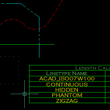
This program will calculate the total length of Lines/Polylines/LWPolylines/Arcs/Ellipses/Circles/Splines with an optional filter. The Filter may be used to select only those lines that are on a certain layer, or perhaps have a certain linetype or colour. The results of the calculation can be displayed in an ACAD Table within the drawing, or written to either a CSV or TXT File. The Table-Style may be selected from the drop-down in the main dialog. Main interface The main dialogue box allows the user to filter lines by layer, linetype or colour and select the table style. Multiple selected items can filtered. A filter string may be entered to help the user quickly find the filter items that he/she requires. Options The options dialogue box allows the user to specify which object types should be included and the type of output, table in the drawing, CSV file or TXT file. Demo Function Syntax: LenCal For instructions on how to run the program see here. Any comments, criticism and suggestions are welcome. Either PM me directly, or reply to the original thread. -

LISP to calculate the slope between two elevations in a plan view
Jaru posted a topic in AutoLISP, Visual LISP & DCL
Hello everyone in the forum, thank you in advance for the help you can give me. Ok this is the situation: I've a LISP, that calculates the slopes in a plan view or in the model, and works very well, but i need some changes adapted to this task. I'll try to explain my best. 1. Here is the code (defun c:plevel (/ decs ;|diff|; elist level osm p1 p2 slope strlevel txtelev txthgt txtpt) (setq osm (getvar 'osmode)) (while (and (or (not (setq txtelev (entsel "\nSelect Starting Level Text : "))) (not (eq "TEXT" (cdr (assoc 0 (setq elist (entget (car txtelev))))))))) (princ "\n Nothing selected or wrong object type selected, try again") ) (setq strlevel (cdr (assoc 1 elist)) decs (- (strlen strlevel) (1+ (vl-string-position 46 strlevel))) level (atof strlevel) txthgt (cdr (assoc 40 elist)) ) (initget 6) (setq slope (getreal "\n Enter Slope Like ==> 0.005 : ")) (if (not slope) (setq slope 0.005)) (setvar 'osmode 39) (setq p1 (getpoint "\nPick 1st Point: ")) ;;; (setq diff (mapcar '- (cdr (assoc 10 elist)) p1)) (while (setq p2 (getpoint "\nPick Next Point (Or Press Enter To Exit): ")) (setq level (- level (* (distance p1 p2) slope)) strlevel (rtos level decs) txtpt (getpoint "\nPick Text Place For Point Level: "); (mapcar '+ p2 diff) ) (entmake (list '(0 . "TEXT") '(100 . "AcDbEntity") '(100 . "AcDbText") (cons 10 txtpt) (cons 11 (list 0.0 0.0 0.0)) (cons 40 txthgt) (cons 1 strlevel) '(50 . 0.0) '(41 . 1.0) '(51 . 0.0) '(7 . "Standard") '(71 . 0) '(72 . 0) (cons 210 (list 0.0 0.0 1.0)) '(73 . 0)) ) (setq p1 p2) ) (setvar 'osmode osm) (princ) ) 2. Basically, what the LISP does is obtain through the slope introduced the levels at the points that the user subsequently enters. To this point, well. Ok, this is what i need 1. It does not calculate the negative slope, if the user enters a negative slope this sends an error message. calculation is not possible in that situation. I need change that to work with negative slopes. 2. that allows me, by selecting objects either line, polyline to calculate the distance first and then with the previous selection of levels, calculate the slope automatically. post the original LISP, Regards. plevel.lsp -

Addition in commandline while in command
3dwannab posted a topic in The CUI, Hatches, Linetypes, Scripts & Macros
Hi all, Is this possible. I was wanting to say stretch a wall in brick dimensions so would it be possible to type the equivalent of '225*9' (which doesn't work) while in the stretch command to give me the correct value every time. Would be a huge time saver at the moment. Even via lisp or any program for brick dims would be sweet. -
Hi guys, I have a requirement to create a block with a few attributes, but the attributes require a bit of composition behind the scenes. Here's an abstract example. I need a block that represents a computer's identity. Each computer has 2 references that need to result in attributes that I can extract. One attribute is a unique reference across the project, and the other attribute is a room reference, and many computers can be in the same room. Here are some example references. Computer A Unique Reference: DF.SALES.01 Room Reference: DG.SALES.07 Computer B Unique Reference: DF.SALES.02 Room Reference: DG.SALES.07 Computer C Unique Reference: DF.SALES.03 Room Reference: DG.SALES.07 Computer D Unique Reference: DF.ADMINISTRATION.01 Room Reference: DG.ADMINISTRATION.02 Computer E Unique Reference: DF.ADMINISTRATION.02 Room Reference: DG.ADMINISTRATION.02 As you can see from the above, the 'common' part for a computer is the middle 'SALES' or 'ADMINISTRATION' part, which 'technically' only needs to be put in/typed in by the user once for each computer. I need to automate this process to reduce user input error, such that they only enter 'SALES' or 'ADMINISTRATION' once and don't end up creating the below, which would be invalid. Computer F Unique Reference: DF.RECEPTION.09 Room Reference: DG.SALES.07 Thus I imagine I need a third property/field/attribute to specify 'room', and then formulate the Unique Reference and Room References, using this 'room' part in the middle. The end goal here is that I need to be able to extract the above two references for each 'computer/block' and get them into Excel, and I need to be able to modify the 3 properties (room, unique reference and room reference) quickly, ideally using something like EATTEDIT, which is how we have edited attributes in the past. Apologies that this may seem like an odd request! The use case above is abstracted, it's actually not for computers at all but I figured it would make more sense than complicating it with the actual application! Many thanks in advance for any thoughts.
-
HELLO AGAIN CADTutor! I have a problem of weather of not you can change the accuracy of the calculation of areas in AutoCAD 2011. In my line of work, we need to find the areas to exact precision, though it seems that my AutoCad is messing with the calculations and rounding up. E.G AREA - .017666 and turns it into .002 I calculate the Area thorught the usage of Polylines, and or the area command when i need to. Can anyone please help me find some insight on to this, mabye to change it to give me EXATE AREA!? Any and all help is greatly appreciated, those who are deemed awesome get a virtual cake, and the cake is NOT a lie....
-

Can ACAD figure out the angle to put a line of specific length between parallel lines
Craigers posted a topic in AutoCAD Beginners' Area
I hope I can explain this simply enough: I am drawing a diagram to describe a mathematical word problem. Since it is easier to visualize with a drawing, I want to draw it using the given dimensions. But angles used in the diagram are unknown and are not needed for the answer to be calculated, so the only way to draw this freehand is to guess at the angle resulting in the correct distances to be off. Here is the word problem: There are two ladders, one 40 feet and the other 30 feet, each touching the base of one of two buildings and leaning against the other building. If the ladders cross 10 feet above the ground, how far apart are the buildings? So for my drawing, being rather simple considering what AutoCAD can do, results in this: Can AutoCAD calculate the angle needed to place a line of a given length between two parallel lines that are a distance apart less than the length of the line to place between them, having the endpoints of this line touching the parallel lines, fitting exactly? For the word problem, the distance between the two parallel lines is what needs to be solved and the math is quite invloved, having to find the roots or solution of a quartic equation. (I have the solution figured out to be 26.03287754 feet) What I am afraid of is that this would require to program an AutoLISP routine to create a new command that one can call from the command line. I see it using the the measure command with relative and absolute co-ordinates. This may be far from a "beginner" question. I can do this quite easily on a peice of paper: having two parallel lines drawn, take a ruler and placing the "0" mark on one line, then adjusting the angle until the desired length just reaches the opposite parallel line. I used to use this trick quite often when drafting with pencil and paper to divide a distance into a required number of even amounts, so this can't be that difficult to do with AutoCAD! If anyone needs further details just let me know! -
Is it possible to input an arithmetic expression (like 0.7*24) when a command asks for input value? For example during offset command. I thought it is possible to use calculator command inside a command but there was no success.


