Search the Community
Showing results for tags 'inventor'.
-
I'm running Inventor 2015. I am wondering if there is a way to make custom section arrows instead of what is defaulted on the system? I have clients that have their own standards for drawings and have a custom section arrow and titles. Is there a way to make a custom one without just making a sketch or plain symbol not related to the section? I'm trying to keep the drawing intelligent...
-
I recently updated to Inventor 2015 and since then tapped holes are not displaying correctly in idw. They only show the core drill. My custom hole chart identifies them as tapped holes correctly but I want them to display correctly in the drawing also. Any ideas? Is there a simple setting I have overlooked? Kev. PUNCH BOLSTER 2.zip
-
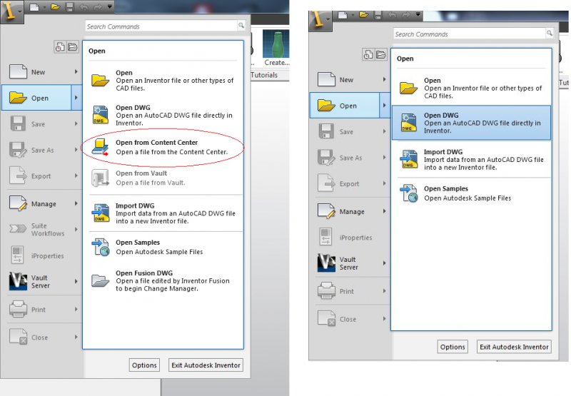
It would seem that the Place Component function can no longer place a Pivot in this version. How can it be done?
-
I couldn't find what this was made with, but is the lathe/mill action from :30 to :50 possible in inventor? I can get the animation to rotate and have the parts spin, but cannot figure out how to make the milling command take the surface down. Might this have been made with Maya? or some CAM software? I was hoping to use inventor to show how to make drill bits and contacts with the parts milled out from a single stock. Any ideas? If not possible, what is a program that I can use that my inventor/autocad skills will be able to translate easily?
-
Hi everyone, Trying to set a view depth in the section view. The instructions say that it's possible. But in inventor 2015 I'm having trouble finding the options that they are explaining and telling you to use. Can anyone point me in the right direction? Thanks!
-
Hello With navigation bar tools we can see the 3d model or assembly, from different viewpoints. Is there any way to get the coordinates of the viewpoint?. Any way to manipulate them ? Thanks Manolis L.
-
Is it possible to display the Center of gravity of the different parts in the bill of materials and parts list? without having to manually define it?
-

Stress Analysis: Use outputs from stress analysis for defining input parameters
petedow posted a topic in Autodesk Inventor
Is it possible to take outputs from the stress analysis such as reaction moments around fixed constraint and to define these as a parameter on input to other parts of inventor. e.g. the force in the downwards direction around a bolt hole modelled as a fixed reaction is 200N. Can you then use this value and input it into a bolt calculator automatically? To avoid having to redo this everytime the model changes? -
When I export from a drawing from Inventor 2014 to model space in AutoCad 2014, all my fonts change. I tried using a few fonts (last one being RomanS). The biggest problem is that when you print from AutoCad after exporting from Inventor, all the text is "hollow" and not filled in. Thanks for any advice you may have, Kyle
-
Hi Brief background; I completed City & Guilds 2D CAD Level 2 and Level 3 back in 2008/09 - I got a draughting job at a manufacturing company and worked there for a couple of years. Since then I have done other stuff to make a living but CAD is my passion! My old CAD tutor introduced me to Inventor last year and I love it! I completed City & Guilds Inventor Level 1 and I'm booked to do Level 2 this September. I really want to dive into Inventor now but what I need is a Laptop that can handle it. I know eventually (when I'm 3D draughting for a living) I will need a laptop that'll be around £800 - £1000. Can anyone recommend a laptop that I can use for practising - the cheaper the better!
-

iLogic for Custom IProperties - how to retain trailing zeroes
DS-precast posted a topic in Autodesk Inventor
Hello All I have a simple iLogic Rule which converts the Mass (kg) iProperty into a Custom iProperty measured in tonnes, to 2 decimal places. [color=#800080][b]iProperties[/b][/color][color=#000000].[/color][color=#800080][b]Value[/b][/color][color=#000000][b]([/b][/color][color=#008080]"[/color][color=#008080]Custom[/color][color=#008080]"[/color][color=#000000], [/color][color=#008080]"[/color][color=#008080]Weight (T)[/color][color=#008080]"[/color][color=#000000][b])[/b][/color][color=#000000][b]=[/b][/color][color=#800080][b]Round[/b][/color][color=#000000][b]([/b][/color][color=#800080][b]iProperties[/b][/color][color=#000000].[/color][color=#800080][b]Mass[/b][/color][color=#ff0000][b]/[/b][/color][color=#000000][b]1000[/b][/color][color=#000000],[/color][color=#000000][b]2[/b][/color][color=#000000][b])[/b][/color] The problem I have is that the iProperty value seems to remove trailing zeroes, (ie. it will display '0.8' when I require it to display '0.80'. Could anybody please indicate how to overcome this issue? Many thanks -
My inventor works just fine and I can get to the content center where the list of fasteners, bolts, nuts, etc. and it opens everything. My co-worker does not have this listed in his drop down. How was this switched off/disabled and how would he get this back? We don't have this file location linked and if I remember correctly he had it at one point last year. Everything I have read points to the vault but we have never used it or ever logged into anything with inventor. When I tracked the "family" files on each of our desktops it appears that I have many and he has few. Any help would be appreciated as right now we open the content center on mine, save as copy to the shared server and he opens it from there, not the best way to do things.

-
Hello all I am developing a parametric model of a precast stair using Inventor 2013. I have set a parameter call "rake" to define the rake distance of the stair (the distance the nosing of each tread protrudes over the tread below - usually about 25 mm) This is initially set to 25 mm in the sketch. If there is no rake, I set this to 0 mm, and this gives a perfectly horizontal & vertical stair profile. If I then set this back to 25 mm, Inventor flips (reverses) the direction and the profile produced is incorrect (it is like a negative rake angle). I guess it is because when I set the rake to 0, the two points are directly in line vertically, and when I set it to 25 mm again it pushes them 25 mm apart horizontally, but in the wrong direction. Is there any way to constrain these parameters or points such the distance is measured only in the desired direction, or to stop one point from going beyond the vertical position of another point. Any help on this matter would be very much appreciated. Many thanks in advance.
-
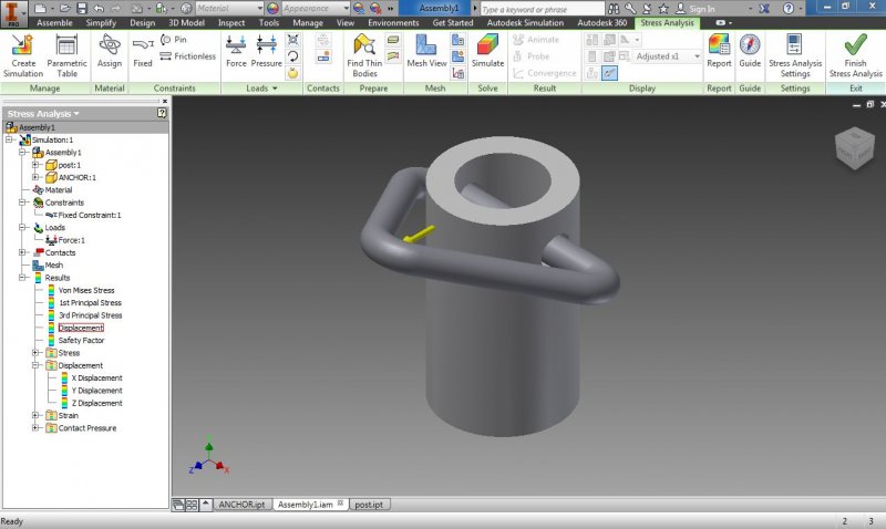
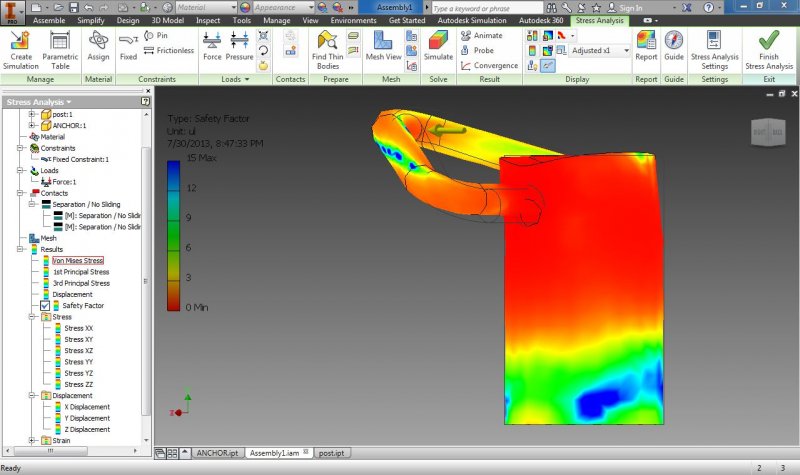
Dear all, I have two parts that put together. Basically a triangular ring is put into a hole of a hollow cylinder. The triangular ring (0.5 dia) could freely move inside the hole (0.625 dia). I need to do a FEA analysis, my steps are 1. I mate the centerline of the hole to one of the axis of the triangle ring, so they line up (as least visually), then click OK. AND then delete this constraint 2. Start FEA analysis, put fix constraint at the bottom of the cylinder, add force to the ring 3. ADD 2 contacts (separation, no sliding) 4. RUN I cannot believe the result. I apply 50 lbf only, but the safety factor is close to zero. Do my steps right??? Pictures and parts are attached. Inventor 2014 Question.zip
-
Dear all, I want to buy Inventor for my work. However, I cannot afford USD4000 to buy the latest version. Is there any place that sell Inventor at a lower price? I don't mind to buy an old version (maybe 2012 instead of the latest 2014) Thanks
-
Apologies in advance if this isn't in the most appropriate category. I recently started work at a marketing firm that was seeking people experienced in Revit. I used it a lot in school so I thought, awesome. When they told me more about the position, they told me I'd be using the software to create furniture pieces that'll go into rendered floorplans and their goal is for the pieces to look as real as possible in the rendering. Creating pieces wasn't something I did a lot of in my classes but I thought a challenge would be welcome. The problem is that I have one coworker who did very basic training in the software and that's it. No one else knows anything about Revit so I figured this is a good place to ask. I've found that tables are easy. Anything with edges, I'm fine with. But when pieces are supposed to have softer edges (like pillows, beds, chairs, etc) I'm having more trouble with making them. I've tried using the Model In Place option and the start from scratch option where I just go right into making a new component. It's a bit time consuming, but I'm hoping it's just because I'm new at it. I've even used the 3D Modeling part of AutoCAD 2013. It does make cushions easier but there's still some things I'm just not able to figure out. My main question is this: is it possible to make detailed/realistic furniture pieces for Revit (like things I would find on RevitCity) in Revit itself or should I use other AutoCAD software. The other two I've been looking at were Inventor or 3DS Max. I used Inventor a bit in classes for designing mechanical pieces and loved it. I've never used 3DS but I checked into it on YouTube and the videos show plenty of things I could use at work. Any helpful opinions on the matter would be greatly appreciated. I don't mind if I end up having to learn another program, as long as it makes things smoother and quicker in the long run.
-
Hello everyone, I'm having some some issues with a sheet metal part I'm working on. Im very new to the inventor software, but can work thru most thing i come across. Our issue: We are designing a chute to fit around an inclined conveyor inside of a tank. I have made the sheet metal part by lofting two sketches on separate planes. The issue I'm having now, is that I cant cut a section of the sheet metal for clearance of the conveyor. I seem to get an error every time i try it. I even tried to convert it back to a standard part and try to a do an extrusion of the part to get it to cut it out, no luck. I will attach my part, I have the box in a sketch that needs to be removed from the sheet metal planes. If someone could please lead me in the right direction of what I need to do, and explain what I'm doing wrong, I would highly appreciate it. Thanks everyone Inventor 2010 Professional chute help.ipt
-
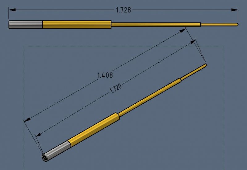
I have been racking my brain as to how to make this work and am at a loss so please help me figure this out. I have a simple assembly of a pin and hood. The pin has a spherical end and the hood has a fillet edge that continues to wrap spherically inward. When trying to dimension the OAL on the side view it is easy and obvious. When trying to do it on the iso view the measurements are never correct. I do not have a good point to choose from on the hood as it has a fillet edge not a square point, which would be easy. Without a flat surface to go off of and in the paper space there is no way to specify quadrants/edges/planes when annotating. The space bar trick helps but does still does not dimension to the right point. When I try to use the RETRIEVE DIMENSIONS action, I can get the OAL of the pin and OAL of the hood separately, but not as an assembly OAL. I tried to go into the assembly and create random sketches, planes, fake dimensions that might be used by the retrieve dim action, but to no avail. This is the simplest part I am using as a reference, I have much more elaborate parts that are giving me the same issue. It would seem straightforward, but for the life of me cannot find an easy way to get that simple OAL. Thanks for the help. Go Sun Devils!
-
I have an assembly (with 4 parts) that I am creating a part table for. I am getting more familiar with iParts and iProperties, but have not found how to connect the revision on the part drawings to the table of the assembly. Everything I have read points to using the Vault but I have never set that up. Is this going to be the answer moving forward or is there a simpler way of achieving this? I am assuming that getting the Vault implemented in everyday use will be the best so that may be my next headache. Any good references or information would be great. Have a great St. Patrick's Day! -Kelly Patrick
-
Good day, dear Forumers, just recently our company partially switched from AutoCAD to Inventor, my department however still works with AutoCAD. This however means that I am required to edit "2D" sketches made with inventor. After struggling a bit with converting the new format into something I can actually select, I've come across a new problem: once I dissolve the block which contains the main model I am unable to convert the resulting lines into Polylines. only 50% of the lines actually connect to their adjacent lines/arcs. This means I have to redraw half the model, which, as you may agree, is unacceptable. Quite lenghthy web-searches have not been fruitfull. FLATTEN was suggested but I don't have the expess tools installed and don't think I can convince the admin to do so. Also it seems that All lines/arcs in question already are on the same Z level, namely 0. Thanks in Advance, CP++
-
Dear all, I have problem with the global axis. I thought they were fixed, but it may not. Somehow I rotated the global axis NOT the model. I am not able to change it back. In other words, if I use the "rotate" function and try to see the front view of my model, it is not really the front view because of the global axis are rotated. May I know how to solve it. Thanks
-
Hello, I'm new to Cadtutor and would like to thank everyone in advance for any help they give me. I started using Inventor Pro 2013 a few weeks ago and I love being able model all my ideas. In doing so, I began to wonder what career path I could have with Inventor having no degree? I have a family and I am currently in the military, so i have a couple years to learn and research this path. College is not in my foreseable future but I would take some form of training and maybe even go for a certification by Autodesk. What if any are your thoughts.
-
Hello everyone! So i've been trying to model this part on Inventor, but it's cost me more than what i expected. It is part of an assembly that i'd like to post soon.Maybe you guys could help me with this. As it is in spanish, both "PASO 2" and "12 giros" stand for Step: 2, and 12 Revs., respectively. All dimensions are in millimeters. Thanks PS: Sorry for my bad english.
-

How to create this baseline dimension style in Inventor 2008?
zmarcoz posted a topic in Autodesk Inventor
Please help. This is my company format. I need to find out how to set the following format. Thanks. If you know how to do it in other version, please tell me too. I guess different version would still use similar style setting method. http://images.books24x7.com/bookimages/id_9010/fig212_01.jpg -
When exporting to an IGES format the threads are missing. Why? Thanks, Victor