Search the Community
Showing results for tags 'inventor'.
-

Save A Copy As AutoCAD .dwg - preserving arc properties
ndogg1080 posted a topic in Autodesk Inventor
Hello, I have Inventor 2008 SP2 and AutoCad 2008 running on a Windows 7 machine. Since it has been installed on this machine, I am having trouble saving an Inventor 2D drawing as an ACAD 2D drawing. The drawing translates OK except that the radii in the Inventor Drawing turn into many small line segments in the ACAD drawing. This is a problem for purposes of dimensioning and exporting to CAM software. Can anyone help remedy this? Many thanks. -
Hi All not so much of a problem now, but im wondering if anyone else has experienced this and could explain how it might have happened. i was updated two sets of drawing border templates for Inventor 2010, im still trying to entice the rest of the design team to use vault......its a scary concept for some, theyve only been using inventor for 4 years. newho the first border before any changes were made, we tried to put into vault, only to find 5 or 6 bmp image files associated with it. the bmp files didnt actually exist and i ended up having to remake the template (not such a bad thing because it was badly out of date and was easier from scratch than moding) the 2nd template file we used regulary and had been putting it into vault with no problem. The only change i had done was to create a new sketched symbol that was our company logo and address to replace our old one. the sketched symbol didnt have any images associated with it or inserted (the logo was created using hatching) but when we came to check the file into vault, it had these 5 - 6 bmp files linked to it preventing it from going in. is there a way to break the links in 2010? i spoke to someone with 2011 who could do it easily......but then i couldn't use the files Cheers R.D
-
Hi Folks, Got an issue with Planetary (internal) gears and dynamic simulation. basically, i have one sun, one planet and one carrier -internal gear. All are designed to move freely. I can get the DS to work fine, providing I dont contstrain the planar top of the sun to anything. This means when apply force in 3d using my mouse, the sun is free to move up and down the z axis - viewing in 2d and applying force in 2d, the mechanism appears to work as intended only becasue its impossible to apply force to the 3rd axis (z) while viewing from this angle. So the obvious solution is to apply a planar mate for the top of the sun, to another part or plane... right??? That's what I thought, however when i do so to restrict the suns movement on the z axis, and return to Dynamic simulation, the suns rotation locks!. Now the sun doesn't move at all and the planet and solar system just revolve around it. Sheesh - I've racked my brains to figure this one out and i'd really appreciate it if someone here could help. I've attached the assembly file for your reference - PS the assembly attached DOES not have the planar mate constraint applied. Moving to DS and viewing from "front" you will be able to see see the motion as intended when applying force (using your mouse) on the sun - notice how all 3 components rotate? Now try viewing in 3d and applying the same(ish) force - you will notice the sun now moves along the z axis. My question : how on earth do i fix this? 6.7mb file - assembly to use is reversing_mechanism2 http://nasora.com.au/test.zip Thanks.
-
Hi Guys, New member here - although I must confess to reading posts on this board for quite a while now. Thanks for all the helpful comments. It's a question that comes up from time to time. Rather than asking a general question, I wanted to ask in form of a list. 1. Someone commented a couple years ago (I think... it may have been more recent) that he observed more students signing up to learn Solidworks than Inventor and that it was the first time this has occurred. Has this trend continued? Do you see Solidworks gaining more popularity? 2. Relates to question 1. Has Autodesk done anything to counter this trend in terms of pricing? I have asked around and found out Inventor sells for 3,300 (Not Inventor LT or professional). Posts from a couple years ago mentioned of that Inventor ranges 4,000-5,000. It seems to me that Inventor prices has come down. 3. For someone in product design that is in the computer peripheral industry - designing products like ergonomic computer mice (quite of bit of curves) and keyboards, which product do you recommend getting? Obviously this person is me and I plan on also getting Alias if I get Inventor. I've asked around and the combined cost of Inventor (regular) and Alias (design) is around 7,000, which I think is pretty comparable with Solidworks. Please correct me if I'm wrong and if Solidworks sells for less. I figured the Inventor+Alias combo is cheaper that getting the inventor premium suite. 4. Which product is better for patent drawings? As some of you may already know, USPTO only accepts drawings with black and white colors only. The color grey or prints made in greyscale is forbidden. They do not allow any shades done in grey. If shades are included they must be in forms of black lines. Do either program provide a way to include shades made with black lines? Thanks in advance!
-
Hi, I am using Inventor 2012 and have created some products, but want to show them in their environments by using the 3D (HDR) backgrounds. There are some 3D backgrounds already installed (empty lab, old warehouse etc) if anyone could tell me where to get more it would be much appreciated. Thanks in advance, Lewis.
-
I was wondering if anyone knew if you could get a 30 day trial, or a student version like you can with AutoDesk. If I do have to pay for the license how much would it be for a student and a full version of this software? I do know how to use Inventor, Revit, and Sketch Up, and I have heard about this software being like the "Mercedes" compaired to Inventor. I would like to learn how to use this software. Thank you all in advance for the help.
-
Hi Guys, I was wondering if someone could help me with a dilemma I've been having. I am designing a chair, and require to put some fillets on the ends of the arms, but it wont let me. I have narrowed the problem down to something to do with the rail that I am using for my loft to follow. The profile of the arm allows a fillet, as I have tested with simple extrudes and lofts, but as soon as I implement the rail for it to follow it doesn't allow the fillet. Any one know why this is? Is it something to do with tolerances, eg: there isn't enough 'room' for the fillet to work, due to the direction of the rail. (that doesn't make sense, lol, sorry). I just don't understand. Anyway, enough waffle, I'm attaching some files to help explain what I want and mean, also for the brave please find attached .zip of my current part (please forgive the messiness) Thanks for any help in advance guys, really appreciate it. Josh edit: hmm couldn't attach or insert image or .zip. Sorry, I've uploaded them to my site if you can see them there, sorry guys just kept getting error messages. http://joshuakeenes.co.uk/cadtutor/chair_fillet_explain.jpg http://joshuakeenes.co.uk/cadtutor/Part4-to-show-jk.zip
-
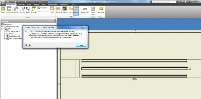
G'day, I have a stange inventor problem i am hoping some one can help me with. I am currently running Inventor Professional 2011. The problem occurs when attempting to create a section view, detail view, croping or any other type of view editing command in the .idw drawing. First of all i place my base view, then when i am wanting to section or any of the other i get this error message 'The specified inputs did not create sweep geometry (faces and/or edges). Try by changing path geometry and/or creating the profile on a sketch plane that is perpendicular to the path and contains one of the path vertices.' Now the strange part is that if i reduce the length of the Part i do not get the error message. It seems inventor can not handle very long parts (my part is approximatly 1000 metres long) is there a way that i can create section views/ detail veiws/ crop ? I have attached a screen shot. thanks.

-
i have lofted two different triangles made by using line. they lofted fine but it is see through, how do i make it opaque? i use inventor 2013
-
Hello everyone, I'm new here! I wanted to ask if anyone is as excited as about the new public beta of Inventor Fusion being released sometime this month!? According to their Facebook page, it seems really interesting. Thoughts?
-

Rendering the video, it is only rendering positive Z from the Origin!
numberOCD posted a topic in Autodesk Inventor
HELP! I'm rendering the video for an animation in Inventor and right now for a sequence of the film it is only rendering points with a positive Z coordinate. Any clue how this can happen? A fade has been applied to 2 components with negative Z coordinates, one of which is active taking away only the roof of a warehouse to see the interior. -
Inventor 2012: Control rotation speed? Don't want it to stop, just decelerate
numberOCD posted a topic in Autodesk Inventor
I'm working with rotating wheels and am trying to figure out how I can go from 60 rpm to 30 rpm with no stop? -
Installed autocad 2012 c/w Inventor fusion. Inventor opens and works except there is no options in the application icon. There seems to be no way of choosing file type when opening new or save as . I have tried to repair and i have uninstalled and reinstalled. Installed as a stand alone complete with service pack 3. Is it me or inventor ? Some help on this would really be appriciated. Thanks to all that read this and hopfully reply to.
-

Client wants autocad dwg title block with attributes... can I use Inventor?
Doove posted a topic in Autodesk Inventor
Morning CAD monkeys, you all have my permission to take 5 and have a coffee. Whilst you're doing so, has anyone come up with a workaround for my problem; my client uses a document management system that only supports autocad dwg files. The contract states I must use their title block, set up with attributes. We put the drawing on their template, it uploads (usually enough time for coffee and a biscuit), the system populates the attributes then you can download the 'issued' revision. How do I work around this if I want to use Inventor? There is also a bit of a problem with the ctb file and layers but I can work around this by setting up inventor dwg template to suit. Any and all help appreciated. cheers Doove -
I have a frame consisting of 4 members that was produced with a skeletal sketch and the frame generator. I want to make this part either have a table driven amount of configs at different sizes. Or a custom spec form when it is entered into an asm... i think this could be done with i logic? I have made configs of other files but they where parts so i used the iPart function. Any help would be great I am using IV 2011 Pro
-
Hi all Ive just discovered how to set objects onto the reference layer in inventor through the part/assembly browser. I have also managed to get into the Styles Manager to edit the linetype reference items are dropped in as. I've even managed to sort of out the nice little cropping function it threw in for a laugh.......... Is there a way to control the transparency of reference objects? It doesnt matter what linetype it is set too, it always becomes 'transparent' once set to reference. I can see where it useful, but in other cases not so much. Any help much appreciated!! R.
-
Hi everyone, just wondered if there is any huge differences/ benefits of changing from Inventor 2010 to 2012. My boss has the offer to get an upgrade to 2012 but if he doesn't do it now then if he wishes to do it in the future it would cost allot more. Anyone else been in this situation or upgraded without any problems. any advice or pointing me in the right direction would be great thanks. Nathan
-
Hi guys im new to this forum and i have a question about inventor. is there a way to know ho much time i have spent on a modell or assembly? Ive been making some changes in some parts but i need to know if its really worth it, and how much modelling or editing time it takes. thank you very much and sorry for my bad english
-
Hi, i have a problem, whenever i modify sketch like creating a hole and come back to part modeling, its not getting updated. Also, I want to create a part and add it to the my own library as a standard part and create family using iPart, is it possible. Thanks heaps.
-
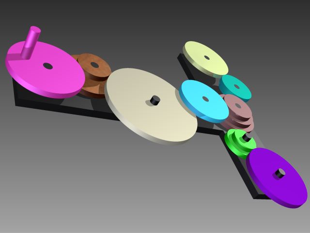
How do I do gears in Inventor 2011? I've found the spur-gear option under the design "tab". But then I get some problems... I've tried to turn my current "wheels" (see picture) into gears, but that don´t seem to be the way to do it. I also tried using component instead of feature, and then I get them to rotate however the gears collide. I don´t know how to solve this or how to do this properly.. Any help is appreciated. //André
-

How to Transfer a Inventor file from 2011 pro version to 2010 edu. version?
tristandoo posted a topic in Autodesk Inventor
At school I use Autodesk inventor 2011 pro and we creat all of are school projects on it. Our teacher told us to download the student software from Autodesk so I did, I downloaded the 2010 pro Educational version and I cant open the files from school in the Educational version and I can't open the files I made in the Educational version on the 2011 school software... could some one please help me.... I need to know how to open them up in both of the programs. -
In my last job we designed boat hulls in Maxsurf and then exported iges surfaces to Catia for all the structures/styling/fitout/drawings etc. If we made a change to the hull we just re-exported the iges, brought it into Catia and then repointed any operations (trims, extracts, offsets etc.) from the old surface to the new one. In fact, there was a shortcut so you only have to repoint one operation, but thats not what my question is about... I'm now with a new company and we design boat hulls in Maxsurf, export iges surfaces and then use Rhino and AutoCAD for everything else, which is as painful as it sounds. I've persuaded them that we need to upgrade to the 21st century and the programs in the running are Inventor, Solidworks and ProE (budget won't stretch to Catia this time). My question is (I got there in the end!): Can you do the same replacing of pointed iges surfaces in Inventor as you can in Catia, and operations will update? I've been doing a lot of research and one thing I've learnt is, just because Catia can do something, doesn't mean the others can... Thanks in advance for your help
-
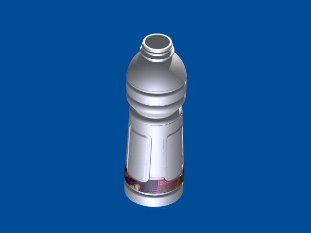
I have some problems with a model of a bottle 1st I can't make a bottle with thickness wall and emboss with the brand or a diferent form than simple bottle. 2nd cant decal the bottle when i make the bottle like a solid. Somebody can help me whit this problem please! cant upload the model cause it too big for upload in the forum but i upload a image of the bottle the form of the emboos its like the gatorade bottle. i use inventor 2011 thanks
-
Our new 2011 software has now been installed and set up although our previous template does not come through and it seems to have disappeared from the 2010 templates folder... any ideas where else it could have located itself:? and if it would just be easier to re create a new template? if so how do you start with a blank page to there on sketch your templates? thanks
-
Hi everybody. I need to make something like an accordion, i have attached the picture what i am talking about, the really problem is that it is not flexible, i can not move it because the the fold can not adapt to the movement when i want to simulate it. I just can resolve the problem of design using sheet metal part and make a contour flange. Is any way to make it possible ans simulate it like real life?