Search the Community
Showing results for tags 'line'.
-
Hello all, I've created a simple room with a sphere that rolls behind an occluder on a ramp. The ramp is made from extruding a line. When I use Trajectory----"conform from" and try to select the line, it doesn't seem to recognize it. In other words, the sphere is not conforming to the extruded line. I'm not sure what's going on, because if I create a simple line, the sphere will traject down it. If someone could take a look and figure it out, it would be a huge help. Thanks Box3.max
-
Hi every one I'm in desperate need for a lisp that can select lines of similar length. Lisp must prompt for a tolerance on the length of line. eg a range -100mm +100mm of the true length I have used qselect, select similar and other lisp files online but they still haven't worked for me. anyone who can help?
-
Hi. I am having trouble with some coding I found elsewhere. I would appreciate it if anyone could give me an insight as to how adjust the coding so that it works. [url="http://www.surveydrawing.net/wp-content/uploads/2012/06/mlin1.png"][img=http://www.surveydrawing.net/wp-content/uploads/2012/06/mlin1.png][/url] [color=#ff0000] ([/color][color=#0000ff]vl-load-com[/color][color=#ff0000])[/color][color=#ff0000]([/color][color=#0000ff]defun[/color] c:MLin[color=#ff0000]()[/color] [color=#ff0000] ([/color][color=#0000ff]setvar[/color][color=#ff00ff] “luprec”[/color] [color=#008000]2[/color][color=#ff0000])[/color] [color=#ff0000] ([/color]Cre_Lay[color=#ff00ff] “dist”[/color] [color=#008000]6[/color][color=#ff0000])[/color] [color=#ff0000] ([/color][color=#0000ff]setq[/color] disttot [color=#008000]0[/color][color=#ff0000])[/color] [color=#ff0000] ([/color][color=#0000ff]setq[/color] lines[color=#ff0000]([/color][color=#0000ff]ssget[/color] [color=#ff0000]([/color][color=#0000ff]list[/color] [color=#ff0000]([/color][color=#0000ff]cons[/color] [color=#008000]0[/color][color=#ff00ff] “line,pline,lwpolyline”[/color][color=#ff0000]))))[/color] [color=#ff0000] ([/color][color=#0000ff]setq[/color] ctr [color=#008000]0[/color][color=#ff0000])[/color] [color=#ff0000] ([/color][color=#0000ff]if[/color] [color=#ff0000]([/color][color=#0000ff]/=[/color] lines [color=#0000ff]nil[/color][color=#ff0000])[/color] [color=#ff0000] ([/color][color=#0000ff]progn[/color] [color=#ff0000] ([/color][color=#0000ff]setq[/color] len[color=#ff0000]([/color][color=#0000ff]sslength[/color] lines[color=#ff0000]))[/color] [color=#ff0000] ([/color][color=#0000ff]repeat[/color] len [color=#ff0000] ([/color][color=#0000ff]setq[/color] ent[color=#ff0000]([/color][color=#0000ff]ssname[/color] lines ctr[color=#ff0000]))[/color] [color=#ff0000] ([/color][color=#0000ff]setq[/color] pntList[color=#ff0000]([/color]ReadPline ent[color=#ff0000]))[/color] [color=#ff0000] ([/color][color=#0000ff]setq[/color] ptCntr [color=#008000]0[/color][color=#ff0000])[/color] [color=#ff0000] ([/color][color=#0000ff]repeat[/color] [color=#ff0000]([/color][color=#0000ff]1-[/color] [color=#ff0000]([/color][color=#0000ff]length[/color] pntList[color=#ff0000]))[/color] [color=#ff0000] ([/color][color=#0000ff]setq[/color] fpoint[color=#ff0000]([/color][color=#0000ff]nth[/color] ptCntr pntList[color=#ff0000]))[/color] [color=#ff0000] ([/color][color=#0000ff]setq[/color] epoint[color=#ff0000]([/color][color=#0000ff]nth[/color] [color=#ff0000]([/color][color=#0000ff]1+[/color] ptCntr[color=#ff0000])[/color] pntList[color=#ff0000]))[/color] [color=#ff0000] ([/color][color=#0000ff]setq[/color] thr[color=#ff0000]([/color][color=#0000ff]distance[/color] fpoint epoint)) [color=#ff0000] ([/color][color=#0000ff]setq[/color] fou[color=#ff0000]([/color][color=#0000ff]angle[/color] fpoint epoint[color=#ff0000]))[/color] [color=#ff0000] ([/color][color=#0000ff]setq[/color] ang[color=#ff0000]([/color][color=#0000ff]*[/color] [color=#ff0000]([/color][color=#0000ff]/[/color] fou [color=#0000ff]pi[/color][color=#ff0000])[/color] [color=#008000]180[/color][color=#ff0000]))[/color] [color=#ff0000] ([/color][color=#0000ff]if[/color] [color=#ff0000]([/color][color=#0000ff]and[/color] [color=#ff0000]([/color][color=#0000ff]>=[/color] ang [color=#008000]90[/color][color=#ff0000])[/color] [color=#ff0000]([/color][color=#0000ff]<=[/color] ang [color=#008000]270[/color][color=#ff0000]))[/color] [color=#ff0000]([/color][color=#0000ff]setq [/color]ang[color=#ff0000]([/color][color=#0000ff]rtos[/color] [color=#ff0000]([/color][color=#0000ff]+[/color] ang [color=#008000]180[/color][color=#ff0000])))[/color] [color=#ff0000]([/color][color=#0000ff]setq[/color] ang[color=#ff0000]([/color][color=#0000ff]rtos[/color] ang))) [color=#ff0000] ([/color][color=#0000ff]setq[/color] txt_ins[color=#ff0000]([/color]MidP fpoint epoint[color=#ff0000]))[/color] [color=#ff0000] ([/color][color=#0000ff]command[/color] [color=#ff00ff]“._Text” “j” “bc” [color=#000000]txt_ins[/color] “1.75″ [/color]ang [color=#ff0000]([/color][color=#0000ff]rtos[/color] thr[color=#ff0000]))[/color] [color=#ff0000] ([/color][color=#0000ff]command[/color] [color=#ff00ff]“._Change”[/color] [color=#ff0000]([/color][color=#0000ff]entlast[/color][color=#ff0000])[/color][color=#ff00ff] “” “p” “la” “dist” “”[/color][color=#ff0000])[/color] [color=#ff0000] ([/color][color=#0000ff]setq[/color] disttot[color=#ff0000]([/color][color=#0000ff]+[/color] disttot [color=#ff0000]([/color][color=#0000ff]distance[/color] fpoint epoint[color=#ff0000])))[/color] [color=#ff0000] ([/color][color=#0000ff]setq[/color] ptCntr[color=#ff0000]([/color][color=#0000ff]1+[/color] ptCntr[color=#ff0000]))[/color] [color=#ff0000] )[/color] [color=#ff0000] ([/color][color=#0000ff]setq[/color] ctr[color=#ff0000]([/color][color=#0000ff]1+[/color] ctr[color=#ff0000]))[/color] [color=#ff0000] )[/color] [color=#ff0000] ([/color][color=#0000ff]princ[/color] [color=#ff0000]([/color][color=#0000ff]strcat[/color][color=#ff00ff] “\nTotal distance :”[/color] [color=#ff0000]([/color][color=#0000ff]rtos[/color] disttot [color=#008000]2 4[/color][color=#ff0000])))[/color] [color=#ff0000] )[/color] [color=#ff0000] )[/color] [color=#ff0000] ([/color][color=#0000ff]princ[/color][color=#ff0000])[/color] [color=#ff0000])[/color] [color=#ff0000]([/color][color=#0000ff]princ[/color][color=#ff00ff] “\nType \”MLin\” to Measure each Segment of the Polyline.”)[/color] [color=#ff0000]([/color][color=#0000ff]princ[/color][color=#ff0000])[/color][color=#800000]; Function to find the mid point of two points.[/color] [color=#ff0000]([/color][color=#0000ff]defun[/color] MidP[color=#ff0000]([/color]midp_fpo midp_spo[color=#ff0000])[/color] [color=#ff0000] ([/color][color=#0000ff]setq[/color] midp_mpo[color=#ff0000]([/color][color=#0000ff]list[/color] [color=#ff0000]([/color][color=#0000ff]/[/color] [color=#ff0000]([/color][color=#0000ff]+[/color] [color=#ff0000]([/color][color=#0000ff]car[/color] midp_fpo[color=#ff0000])[/color] [color=#ff0000]([/color][color=#0000ff]car[/color] midp_spo[color=#ff0000]))[/color] 2) [color=#ff0000]([/color][color=#0000ff]/[/color] [color=#ff0000]([/color][color=#0000ff]+[/color] [color=#ff0000]([/color][color=#0000ff]cadr[/color] midp_fpo[color=#ff0000])[/color] [color=#ff0000]([/color][color=#0000ff]cadr[/color] midp_spo[color=#ff0000]))[/color] 2[color=#ff0000])))[/color] [color=#ff0000])[/color][color=#800000];Function to Create a Layer with given color.[/color] [color=#ff0000]([/color][color=#0000ff]defun[/color] Cre_Lay[color=#ff0000]([/color]lay_layn lay_laycol[color=#ff0000])[/color] [color=#ff0000] ([/color][color=#0000ff]if[/color] [color=#ff0000]([/color][color=#0000ff]=[/color] [color=#ff0000]([/color][color=#0000ff]tblsearch[/color] [color=#ff00ff]“Layer”[/color] lay_layn[color=#ff0000])[/color] [color=#0000ff]nil[/color][color=#ff0000])[/color] [color=#ff0000] ([/color][color=#0000ff]command[/color][color=#ff00ff] “._Layer” “n”[/color] lay_layn[color=#ff00ff] “c”[/color] lay_laycol lay_layn[color=#ff00ff] “”[/color][color=#ff0000])[/color] [color=#ff0000] ([/color][color=#0000ff]command[/color][color=#ff00ff] “._Layer” “t”[/color] lay_layn[color=#ff00ff] “on”[/color] lay_layn[color=#ff00ff] “c” [/color]lay_laycol lay_layn[color=#ff00ff] “”[/color][color=#ff0000])[/color] [color=#ff0000] )[/color] [color=#ff0000] ([/color][color=#0000ff]princ[/color][color=#ff0000])[/color] [color=#ff0000])[/color][color=#800000];Function to Read Vertices of Selected Lines.[/color] [color=#ff0000]([/color][color=#0000ff]defun[/color] ReadPline[color=#ff0000]([/color]imp_Ent[color=#ff0000])[/color] [color=#ff0000] ([/color][color=#0000ff]setq[/color] glb_obj[color=#ff0000]([/color][color=#0000ff]vlax-ename->vla-object[/color] imp_Ent[color=#ff0000]))[/color] [color=#ff0000] ([/color][color=#0000ff]setq[/color] glb_PntCnt[color=#ff0000]([/color][color=#0000ff]vlax-curve-getEndParam[/color] glb_obj[color=#ff0000]))[/color] [color=#ff0000] ([/color][color=#0000ff]setq[/color] returnPTList ‘[color=#ff0000]())[/color] [color=#ff0000] ([/color][color=#0000ff]setq[/color] ptCntr [color=#008000]1[/color][color=#ff0000])[/color] [color=#ff0000] ([/color][color=#0000ff]setq[/color] glb_oName[color=#ff0000]([/color][color=#0000ff]vlax-get-property [color=#000000]glb[/color][/color]_obj ‘ObjectName[color=#ff0000]))[/color] [color=#ff0000] ([/color][color=#0000ff]setq[/color] glb_OClosed [color=#0000ff]ni[/color][color=#ff0000][color=#0000ff]l[/color])[/color] [color=#ff0000] ([/color][color=#0000ff]if[/color] [color=#ff0000]([/color][color=#0000ff]=[/color] glb_oName[color=#ff00ff] “AcDbLine”[/color][color=#ff0000])[/color] [color=#ff0000] ([/color][color=#0000ff]progn[/color] [color=#ff0000] ([/color][color=#0000ff]setq[/color] glb_EnDetails[color=#ff0000]([/color][color=#0000ff]entget[/color] imp_Ent[color=#ff0000]))[/color] [color=#ff0000] ([/color][color=#0000ff]setq[/color] big_Point3d[color=#ff0000]([/color][color=#0000ff]cdr[/color] [color=#ff0000]([/color][color=#0000ff]assoc[/color] [color=#008000]10[/color] glb_EnDetails[color=#ff0000])))[/color] [color=#ff0000] ([/color][color=#0000ff]setq[/color] end_Point3d[color=#ff0000]([/color][color=#0000ff]cdr[/color] [color=#ff0000]([/color][color=#0000ff]assoc[/color] [color=#008000]11[/color] glb_EnDetails[color=#ff0000])))[/color] [color=#ff0000] ([/color][color=#0000ff]setq[/color] returnPTList[color=#ff0000]([/color][color=#0000ff]append[/color] returnPTList [color=#ff0000]([/color][color=#0000ff]list [/color]big_Point3d[color=#ff0000])))[/color] [color=#ff0000] ([/color][color=#0000ff]setq[/color] returnPTList[color=#ff0000]([/color][color=#0000ff]append[/color] returnPTList [color=#ff0000]([/color][color=#0000ff]list [/color]end_point3d[color=#ff0000])))[/color] [color=#ff0000] )[/color] [color=#ff0000] ([/color][color=#0000ff]progn[/color] [color=#ff0000] ([/color]setq glb_OClosed[color=#ff0000]([/color][color=#0000ff]vlax-curve-isClosed[/color] glb_obj[color=#ff0000]))[/color] [color=#ff0000] ([/color][color=#0000ff]setq[/color] glb_2dDist 0[color=#ff0000])[/color] [color=#ff0000] ([/color][color=#0000ff]setq[/color] old_Point [color=#0000ff]nil[/color][color=#ff0000])[/color] [color=#ff0000] ([/color][color=#0000ff]repeat[/color] [color=#ff0000]([/color][color=#0000ff]1+[/color] [color=#ff0000]([/color][color=#0000ff]fix[/color] glb_PntCnt[color=#ff0000]))[/color] [color=#ff0000] ([/color][color=#0000ff]setq[/color] cur_Point3d[color=#ff0000]([/color]vlax-curve getPointAtParam glb_obj [color=#ff0000]([/color][color=#0000ff]1-[/color] ptCntr[color=#ff0000])))[/color] [color=#ff0000] ([/color][color=#0000ff]setq[/color] returnPTList[color=#ff0000]([/color][color=#0000ff]append[/color] returnPTList [color=#ff0000]([/color][color=#0000ff]list [/color]cur_Point3d[color=#ff0000])))[/color] [color=#ff0000] ([/color][color=#0000ff]setq[/color] ptCntr[color=#ff0000]([/color][color=#0000ff]1+[/color] ptCntr[color=#ff0000]))[/color] [color=#ff0000] )[/color] [color=#ff0000] )[/color] [color=#ff0000] )[/color] [color=#ff0000] ([/color][color=#0000ff]setq[/color] return returnPTList) [color=#ff0000])[/color] [/Code] Thanks in advance for your assistance.
-
I have 2 lisp routines help draw bearing line and label them but i would have to do 2 command seperately so i am seeking someone help me combine them together. command 1 is to draw the bearing... ;Tip1741: BD.LSP Bearing/Distance lines (c)2001, Joon Hong $50 Bonus Winner (defun C:BD () (setvar "cmdecho" 0) (initget 1) (setq PT (getpoint "\nPick a starting point: ")) (initget 1 "NE NW SE SW") (setq BR (getkword "\nPick bearing (NE/NW/SE/SW): ")) (setq OPT (strcase BR)) (initget 1) (setq LEN (getreal "\nType the length: ")) (setq DEG (getstring "\nType the degree: ") minx (getstring "\nType the minute: ") SEC (getstring "\nType the second: ")) (if (= DEG "") (setq DEG "0")) (if (= minx "") (setq minx "0")) (if (= SEC "") (setq SEC "0")) (cond ((= "SW" OPT) (setvar "angbase" (cvunit 270 "degree" "radian")) (setvar "angdir" 1)) ((= "SE" OPT) (setvar "angbase" (cvunit 270 "degree" "radian")) (setvar "angdir" 0)) ((= "NW" OPT) (setvar "angbase" (cvunit 90 "degree" "radian")) (setvar "angdir" 0)) ((= "NE" OPT) (setvar "angbase" (cvunit 90 "degree" "radian")) (setvar "angdir" 1))) (command "line" PT (strcat "@" (rtos LEN) "<" DEG "d" minx "'" SEC "\"") "") (setvar "angbase" 0) (setvar "angdir" 0) (setvar "cmdecho" 1) (princ)) (princ "\nType 'BD' to draw lines with bearings") (princ) command 2 is to label the bearing line ; TIP752.LSP Distance and Bearing (c)1992, Roy Cook ;* distance and bearing label for lines (graphscr) (prompt "\nloading. . .") ;convert radians to degrees (defun rtd (R) (/ (* R 180.0) pi)) (defun C:brg2 () ;input for line notations (setq P1 (getpoint "\nfirst point: ")) (while (setq P2 (getpoint p1 "\nsecond point: ")) (setq T1 "text height: <default = " T2 ">: " T3 (getvar "textsize") );setq (terpri) (setq TH (getreal (strcat T1 (rtos T3 2 2) T2))) (if (= TH nil) (setq TH t3)) ;determine if bearings are true north, south, east, or west (defun nsew () (if (and (= (car P1) (car P2)) (< (cadr P1) (cadr P2))) (setq BNG "north") );if (if (and (< (car P1) (car P2)) (= (cadr P1) (cadr P2))) (setq BNG "east") );if (if (and (= (car P1) (car P2)) (> (cadr P1) (cadr P2))) (setq BNG "south") );if (if (and (> (car P1) (car P2)) (= (cadr P1) (cadr P2))) (setq BNG "west") );if );defun ;place text on line (setq AA (angle P1 P2) DS (distance P1 P2) P3 (polar P1 AA (/ DS 2.0)) AA1 (strcat (rtos (/ DS 12.0) 2 2) "'") );setq ;calculate bearing from coordinates and format for printing (defun bearing () (setq O (- (car P2) (car P1)) T (- (cadr P2) (cadr P1)) AZMTH (/ (* (atan (/ O T)) 180.0) pi) A (abs AZMTH) D (fix A) M (* 60 (- A D)) S (* 60 (- M (fix M))) M (fix M) );setq (if (= "60" (rtos s 2 0)) (setq M (+ 1 m))) (if (= "60" (rtos s 2 0)) (setq S 0)) (if (= "60" (rtos m 2 0)) (setq D (+ 1 d))) (if (= "60" (rtos m 2 0)) (setq M 0)) (if (< (cadr P2) (cadr P1)) (setq G "s") (setq G "n")) (if (< (car P1) (car P2)) (setq H "e") (setq H "w")) (setq BNG (strcat G "" (if (< D 10) (strcat "0" (rtos D 2 0)) (rtos D 2 0)) "%%d" (if (< M 10) (strcat "0" (rtos M 2 0)) (rtos M 2 0)) "'" (if (< S 10) (strcat "0" (rtos S 2 0)) (rtos S 2 0)) "''" "" H)) );setq ;bearing and distance on line (if (or (= 0 (- (car P1) (car P2))) (= 0 (- (cadr P1) (cadr P2)))) (nsew) (bearing)) (command "text" "m" (polar P3 (rem (+ AA (/ pi 2)) (* pi 2.0)) TH) TH (rtd AA) AA1) (if (or (> (car P1) (car P2)) (= (rtd AA) 270)) (command "rotate" "last" "" P3 180.0) );if (command "text" "m" (polar P3 (rem (+ AA (* pi 1.5)) (* pi 2.0)) TH) TH (rtd AA) BNG) (if (or (> (car P1) (car P2)) (= BNG "south")) (command "rotate" "last" "" P3 180.0) );if (command "line" P1 P2 "") (setq P1 P2) ) (princ);end program cleanly );defun thank you in advance
-
All my sources say I can create a perpendicular or tangent arc from the end of a line segment by holding down the left mouse button. The Direct Manipulation Tutorial even suggests the arc doesn't have to be perpendicular or tangent. Alas, I have spent far too long trying various permutations of click and hold with not even the slightest hint of an arc to show for it. What am I missing?
-

Long Length Line = jumpy cursor?
LClough posted a topic in AutoCAD 2D Drafting, Object Properties & Interface
(AutoCAD LT 2013) If I draw a lengthy line across the screen, whatever scale I am drawing, the cursor seems to jump a few inches even when I am trying to be extra smooth with the mouse, I have updated my graphics card recently and no real change, what else can I do? Cheers, Lloyd -

Would it be any easiler method to make a solid line to be a partly hidden line?
zmarcoz posted a topic in AutoCAD Beginners' Area
Some of objects that I draw have partly hidden lines. Basically I can create two lines and then set one to be solid and the other one to be hidden. But may I know any faster way to do that? Thanks:D -

Autocad lt 2013 - Line type Help
boxel0 posted a topic in AutoCAD 2D Drafting, Object Properties & Interface
I need a paticular linetype made, i have looked everywhere and have tried making my own but i am terrible. If anyone can do it and send me .lin file with it, i would be hugely grateful
-
I drew a dashed line in model space and it appears as a solid line in paper space. What is going on?
-

What's wrong with this HIDDEN linetype?
lamensterms posted a topic in AutoCAD 2D Drafting, Object Properties & Interface
Hey guys, I've been running both AutoCAD 2009 and 2010 for the last year almost - and I had noticed that the linetypes (specifically HIDDEN) are displayed differently in each version. The linetypes are not symmetrical in 2010. Please see attached image and .DWG for examples. http://dl.dropbox.com/u/69601613/LINE.dwg Does anyone know what controls this? Or how i can fix it? Thanks for any help.
-
I'm wondering how to change the thickness of leader lines. I'm editing a drawing done by someone else and I need to make the leader lines thicker. I tried changing the layer thickness and making sure the settings were such that the leader line thickness would be determined by the layer. I also tried channging the leader line thickness in properties and/or leader styles, but no luck there either. Anyone know what might be going on?
-
Hello, i am new here so please have some patience. i been using autocad for a long time, but recently my entire storage died, im paying allot of money to recover it, but it takes a couple of months.... my problem is this. I have always used the same Plot Style table since college, we build it in class and has worked for me since. now i don't have access to it anymore. I will gladly make new ones, i know how to make them, but I don't remember the pen assignments (linewidth) for every color. I use the basics RED (0.0025) yellow (0.005).... but honestly, it doesn't come out as good as before. does anyone have a list of the linewidth for each color and other settings that would give me a good plot style. I know this is a dumm thing to ask, but im very proud of my plans and hate to see them ugly on paper. Thanks.
-
Hi all and I hope I can put this over properly. Is this possible, as a for instance in Autocad 2011 If I had an heptagan (7 sides) (had to look this up LOL) which was equal sides and I deleted one line, would I be able to move the two end lines together so it is then a Hextegon (6 sides) and they are all still equal??? Or move one of the end lines to close the gap, and all the other lines move with it to keep it in proportion. I have the BIG Autocad Bible but not knowing what the name of this process is, makes it hard for me to look it up. I can select all the lines and move them but not close the gap. Hope this all make sense. Thank you in advance.
-

Edit line weight in nested blocks of all XREF drawings.
crsimmons posted a topic in AutoCAD Drawing Management & Output
The 2D drawings I am working with were exported from 3D REVIT files to 2D AutoCAD files. There are several XREFed drawings that are both mechanical and architectural from the original REVIT files that for whatever reason, the block's line weights came over with line weights of 70 in those blocks. When I plot, the objects are a blur with the line weight so high. I tried using the command "setbylayer" but that didn't work since nested blocks still had lineweights of 70. Is there a VBA or LISP routine to run through all the blocks (including nested) that can change the line weights to a given number? Thank you for any advise/recommendations. -
A very general question, I would like to ask how to draw a certain line and be able to delete part of it. Example 1: I would like to draw a bunch of seried resistors, so I made a bunch of rectangles and draw a wire across them. But there are wire crossing through each one of them, how do I remove/erase that part in between each of the resistor? The line is made by using command: LINE Example 2: Drawing some polygon and random shapes. Simplest example, drawing a half circle, so I draw a circle and want to remove the other half, how do I do it? Yes, I know in example 1 I can do one object first then copy paste... But that is not what I am asking. I am seeking the command how to remove the lines or object in between.
-

Get Line Weight in Layout? Printing OK
D1-Xen posted a topic in AutoCAD 2D Drafting, Object Properties & Interface
I am aware some users like their lines very sharp and neat in the layout and make the line weight appear in the printing process. However, I am wondering if I can see the the lines weight applied while drawing in AutoCAD. Is just I believe it will give a better "print preview" as I am working. It will be very annoying to keep going back to print layout to "hummm... How does the line look?" PS: Yes, I know how to change the line weight. -

how to output the x and y value of line in autocad to text file
renoald posted a topic in AutoCAD Beginners' Area
hai , i have two line in autocad file . How i can output the x and y value for line to text file ? -
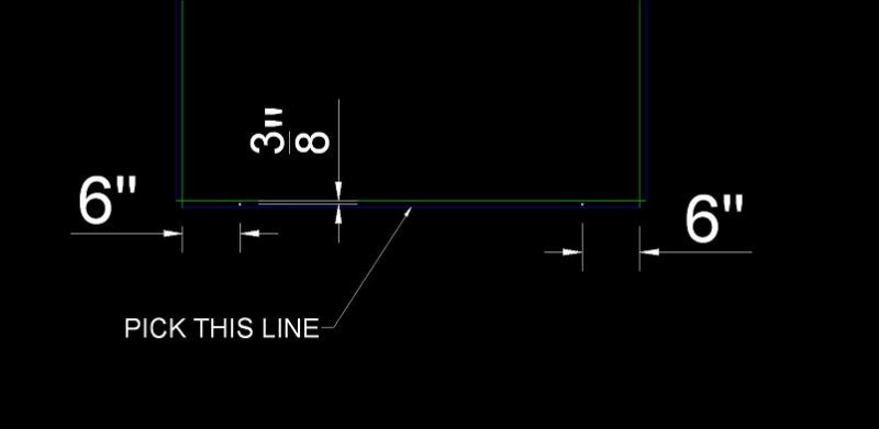
Hi All, I was wondering if there was a lisp routine out there that when you pick a line it would put to circles in between the center of two lines 6" from each end? i've enclosed a file showing what i 'm looking for. Thanks, Brian
-
Hello everyone! I would like some help with a lisp that draws lines from multiple starting points to multiple endingpoints. It would be beneficial if lines did not intersect, and if lines were drawn in 45 angles. I will attach a drawing example of what i want. I never made a lisp before so i dont know how hard this is. I know some scripting (autohotkeys). Nice to find this forum. Hope you can help me / direct me. I am willing to learn. Best regards /T example.dwg example.dwg
-
Hi all, i need some help with this lisp, i managed to modify it to do a triangle but i don't know what to write to make the 3 line to be a different color or layer. if some one could help i would appreciate it. Thanks, Brian Tab Corner.lsp ;;function (myline mypt1 mypt2 mypt3) draw three lines ;;the first line goes from mypt1 to the y of mypt1 and the x of mypt2 ;;the 2nd line goes from the y of mypt1 and the x of mypt2 to mypt2 ;;the 3nd line goes from the x of mypt2 and the x of mypt2 to mypt1 ;;the function dose not ask for the point so it can be called ;;from other programs (defun myline (mypt1 mypt2 mypt3 / mypt4 acadObject acadDocument mSpace myobject) (setq acadObject (vlax-get-acad-object)) (setq acadDocument (vla-get-ActiveDocument acadObject)) (setq mSpace (vla-get-ModelSpace acadDocument)) ;;set up point three (setq mypt3 (list (car mypt2) (cadr mypt1) (caddr mypt1))) ;;add the first line (setq myobject (vla-addline mspace (vlax-3d-point mypt2) (vlax-3d-point mypt3) ) ;_ end of vla-addline ) ;_ end of setq ;;if you need to set properties such as Layers, Linetypes, and Groups for ;;line one do it here ;;add the 2nd line (setq myobject (vla-addline mspace (vlax-3d-point mypt3) (vlax-3d-point mypt1) ) ;_ end of vla-addline ) ;_ end of setq ;;if you need to set properties such as Layers, Linetypes, and Groups for ;;line two do it here ;;add the 3nd line (setq myobject (vla-addline mspace (vlax-3d-point mypt1) (vlax-3d-point mypt2) ) ;_ end of vla-addline ) ;_ end of setq ;;if you need to set properties such as Layers, Linetypes, and Groups for ;;line three do it here ) ;_ end of defun ;;command tbc ;;Ask for the two line point and call myline (defun c:tbc (/ mypt1 mypt2 mypt3) (setq mypt2 (getpoint "Enter First Point")) (setq mypt1 (getpoint "Enter 2ND Point" mypt2)) (myline mypt1 mypt2 mypt3) ) ;_ end of defun
-
Ok, so I have this drawing that I just finished. There were a few dotted lines that were showing up correctly in model space. Then, when I switched over to paper space all of those lines were solid. I messed around with the option LTSCALE and set it to 0.01. This made the lines show up correctly in paper space, but now they are all messed up in model space. Is there an option to make it so they show up exactly the same in both model and paper space? Thanks
-

how to draw a line based on the area of encircles area?
khoshravan posted a topic in AutoCAD General
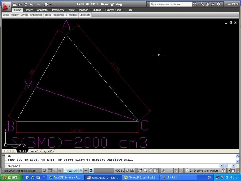
This is more of a trigonometry question, but I want to know if there is an easier ACAD solution for drawing. In the given triangle of ABC (sides and angels are known) I want to draw line CM so that the area of BCM becomes 2000 cm (are of ABC is 5311.7 cm3). Is there an easy ACAD way for drawing this line without using trigonometry for calculation?
-
I created 3 layer states, continuous, hidden, and dotted, for those respective linetypes. I created a drawing using each layer when appropriate. I saved, closed, and opened the file back up and the linetypes were all replaced with continuous (or hidden, etc. it just depended on which layer it opened on). Why is this? I've had this problem before but never figured it out. Why won't AutoCAD save my linetypes?
-
I've heard that you can reduce file size using polyline instead of line while drawing (or vice versa... don't remember) Could you advice please, is it true and what exactly should be used. I think, why we would need the line tool at all if polyline more convenient... unless I am missing something... ?
-

Custom DASHED lines with text
freek posted a topic in AutoCAD 2D Drafting, Object Properties & Interface
Hello community, it's been a few weeks with no activity whatsoever on the forum, but I'm back for a with a good one I've been customizing acad.lin like a maniac for the last couple of days and there's a recurring problem that I can't resolve by myself. I have this line... *EX-DASH,[G] Existing - - EX - - - - EX - - - - EX - - A,.125,-.0625,0.127,-.254,["EX",STANDARD,S=.127,U=0,X=-.127,Y=-.0635],-.2,.125,-.0625,.125,-.0625 The result is similar to... - - EX - - - - EX - - - - EX - - - - EX - - - - EX - - - - EX - - Let's say that the pattern of the line ("- - EX - -", because that's the part that's being repeated) takes 50 units to display at a given scale. I draw a PLINE and one section of the line is like 75 units long. If the line I'm drawing can't contain the pattern of my custom line, it won't display correctly. Given these numbers, the pattern would only display right once (75 / 50 = 1.5). *And the crowd goes DUUUUH!* I get that and it's ok. HOWEVER, one thing I don't get is why autocad displays the pattern once and then fill the rest with a continuous line. It's okay for all my continuous custom lines with text because it keeps the same base line and it feels transparent (and it's also the reason I never realized it was reacting this way until I started working with dashed lines). Example: I want to display "- - EX - - - - EX - -" but would only have space for "- - EX - - - - E". Acad will display "- - EX - -" once + continuous line for the remaining space. I know that if there's no space to fit a second "EX" it can't be displayed, and that's allright, but how come it doesn't fill the rest of my line with dashes instead of a continuous line? With PLINEs, every time I turn a corner, I get this continuous line segment on each corner before it starts displaying the dashes (because I can't always draw lines that fits perfectly the pattern). Any idea on how to force it to display dashes when there's not enough space to repeat the pattern one last time?