Search the Community
Showing results for tags 'lisp'.
-
Hi All: I'm looking for a lisp that will help accomplish the most mundane part of drafting - creating a coordinates table. I've found lisps on the internet that can do this, and actually work very well, here's an example: http://www.cadlispandtips.com/2011/09/lisp-coordinates-with-table.html This actually works great and the output is almost exactly what I want, the only problem is that the table is simply made up of lines / text. Rather than an actual Table with Fields. And while I can re-create the table over and over again, other users of the drawing (that don't have that lisp) will have to manually edit the text. So I'm looking for a lisp that will allow a user to: 1) create points / preferably with a point number 2) automatically outputs the coordinates / points number to a table in the layout view, with the correct text size, depending on scale 3) instead of putting text in the table, will put fields that are linked to each point so that if the points are moved, a simple regen of the table will update the coordinates. This can be done manually by Insert field -> Objects -> Object -> [select point] ->position -> Filter X / Y / X. Sorry if this has been asked before, I'm new to the site and haven't been able to find it yet. Really appreciate any help anyone can provide. JK
-
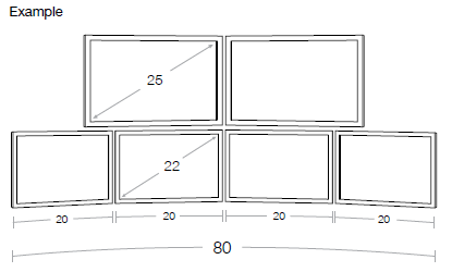
...on how best to proceed. We are all currently running AutoCAD 2010, CAP, and Worksheet. My company sells monitor array bars as part of our offering. We have PNs and blocks for the array bars, but our customers always want to see their specific monitor configuration applied in our drawings. As most of you know there are a million different monitor sizes out there; in addition to that, in the industry we cater to, it is not uncommon for the user to have a number of monitors of various sizes. For example, I am looking at a project with a stacked array; two 25" monitors over four 22" monitors. We are not selling the monitors so those blocks do not need to be attributed for quoting, just need a quick way to create the geometry. At the moment we are drawing these from scratch, which isn't too difficult, but it can be tedious. There are also five people on my team and we all seem to have adopted similar, but different processes for making these. So, what I am thinking is building a Lisp that will spit out the geometry for us. I'd like a prompt that asks something like (using the quantity and sizes from the example I mentioned above): Number of Monitors Over?: 2 Number of Monitors Under?: 4 Over Monitor Size?: 25 Under Monitor Size?: 22 Then, boom, we get something like this: ...the screen and monitor frame will need to be on different layers so that they will render properly. What do you think? Is a Lisp the right way to go here? Thanks in advance, Watson

-

Using a Polygon to create a wipeout for a circle
chiimayred posted a topic in AutoLISP, Visual LISP & DCL
Hey guys, I'm working on a code but I am having issues with getting the DXF codes assigned to a variable and using the variables for the polygon command. Basically what I am trying to do is to create a polygon that "traces" a circle that will help me with the wipeout command. (defun c:test (/ obj) (setq obj (entsel"\nSelect Circle to Wipeout: ")) (setq rad (assoc 40 obj)) (setq cen (assoc 10 obj)) (command "_.polygon" 50 cen "C" rad ) ) I'm getting this error: error: bad association list: (7ffffb05b50> (3241.76 1416.18 0.0)) Any help is appreciated -

Need assistance figuring OSNAP for my LISP! THANKS!
tmelancon posted a topic in AutoLISP, Visual LISP & DCL
Hello all. I have a LISP routine that I have been using forever now so excuse me if it is written sorta outdated to what it could look like if it were updated. It is a balloon(bubble) routine to insert letters or numbers inside a sized bubble with a line and an arrow. The problem I am having is that when running the command after selecting my first point i have to physically turn off OSNAP then after I enter the numbers and finish the command turn OSNAP back on because if I do not it distorts the arrow... I have a mouse with extra programmed buttons that allows me to speed up the process as if it never happens, but still thats not the point. It would be nice to just keep all my snaps on all the time and let the code and just continue to breeze through my drawings. I have tried a few things and I am finished with trying for now. Besides I have others in my cad department that have regular mice and we all believe it could be made better. Figured I would take it to the CAD community, because after all I know this is what some of you live for also. So to sum it up I am basically looking for the code to be revised so that when I start the command it will change OSMODE properly to allow for everything to be entered with no problems. Whether SNAP is turned off/on of OSMODE is altered I do not really care just as long as SNAP IS ON DURING FIRST USER POINT so that my leader is on my pipe and SNAP IS BACK TO ALL ON after the command. THANKS THANKS THANKS IN ADVANCE! Sorry if I am missing it guys, I have tried. Here is the code: ************************ DATAPOINT BUBBLE INSERTION ************************** (defun c:BALLOON (/ oldlayr oldos) (setq oldlayr (getvar "clayer")) (command "._-layer" "s" TEXT "") (initget (+ 1)) (setq pt1 (getpoint "\nDatapoint location on pipe: ")) ; Get 1st loc (initget (+ 1 32)) (command "OSNAP" "NONE") (setq pt2 (getpoint pt1 "\nDatapoint bubble location: ")) ; Get 2nd loc (initget (+ 1 2 4)) (if (= etype "G") (progn (setq dps (strcase (getstring "\nEnter datapoint ID (A1 - A999) or (A1 - AZ99): "))) ; Get DP# (if (< (strlen dps) 3) (setq csize (* (getvar "userr1") 1.2)) ; balloon for A1 (progn (if (< (strlen dps) 4) (setq csize (* (getvar "userr1") 1.9)) ; balloon for A22 (setq csize (* (getvar "userr1") 2.3)) ; balloon for A333 ) ) ) ) (progn (setq dpnum (getreal "\nEnter datapoint number (1.0-999.9): ")) ; Get DP# (setq dps (rtos dpnum 2 1)) (if (< (strlen dps) 4) (setq csize (* (getvar "userr1") 1.6)) ; balloon for 9.9 (progn (if (< (strlen dps) 5) (setq csize (* (getvar "userr1") 2.0)) ; balloon for 99.9 (setq csize (* (getvar "userr1") 2.4)) ; balloon for 999.9 ) ) ) ) ) (command "._circle" pt2 csize) (setq a (angle pt2 pt1)) (setq OLDOS (getvar "OSMODE")) (setvar "OSMODE" 0) (command "._line" pt1 (osnap (polar pt2 a csize) "nearest") "" ) (setvar "OSMODE" OLDOS) (command "._solid" pt1 (polar pt1 (- a 85) (getvar "userr1")) (polar pt1 (+ a 85) (getvar "userr1")) "" "") (command "._text" "m" pt2 (GETVAR "USERR1") 0 dps) (command "._-layer" "s" oldlayr "") (prin1)) -
hey guys, I am working on converting some 3d solids into usable 2D dynamic blocks and I am working on writing a quick little lisp that will help speed it up. (defun c:test (/ obj obj2 bp name) (setq obj (entsel)) (command "_-view" "_top" "flatshot" '(0 0) 1 1 0 "_erase" obj "" "_explode" "_all" ) (setq obj2 (ssget)) (setq bp (getpoint "\nWhere is basepoint?: ")) (setq name (getstring T "\nWhat is the name of the block?: ")) (command "_block" name bp obj2 "" "_insert" name '(0 0) 1 1 0 "wblock" ) ) my issue is with the wblock command, is there a way to get the dialog box to open? if not i need to export the block file to a different file path (not every time but most)... what would be your approach? Thanks!
-

Getting Coordinates of a polyline with a constant X step
Steven29410 posted a topic in AutoCAD General
Hello everyone, in order to obtain a seabed profile for a school project, I need to get the Y coordinate of a polyline on several Kilometers with a fxed X step of 2m between each point. For the moment, the only manual solution I have found is to create a vertical line every 2m and to get the distance between the intersection of this line with my polyline and an horizontal line representing the mean sea level. Is there any way to automatize it because it is very long to do manually and I don't have enough time ? I did not succeed in doing this with dataExtraction. I also found on the internet a LISP file which extract the coordinates of points contained in the window. Nevertheless, I was told it is not possible to create automatically points on a curved polyline with a fixed x step. What I need at the end is an excel file of this type to use it in another software: X(m) Water Depth (m) 0 15.121 2 15.134 4 15.147 ... ... I precise I am a beginner in autocad, I have started today. Have you got any idea to solve this problem ? Thank you in advance -
Hi, I am very new to lisp and AutoCAD with no previous experience. I am working on a project which I’m finding pretty difficult. What I am trying to do is import attributes and properties associated with a sphere from a .csv file into the corresponding property set in AutoCAD. I found a solution online which will allow me to import the coordinates (x,y and z) and this works a treat. However, I am having difficulty trying to import attributes associated with the sphere into the extended data property sets. So say for example, I am trying to import the week number, a reference and a description in from the .csv file into AutoCAD, under properties and extended data. Would anyone have any guidance or direction they could give me? Anything at all would be greatly appreciated. Thank you in advance!
-
I have looked at many of threads, but I did not see the resolution for getting my right mouse button back to normal. this was in a thread I followed and it summed up what I have best. I use Autocad 2009, I'm a Cad newbee, and I appear to have somehow messed up my right click short-cut menu settings. Before, I could right-click and get all of the edit options (delete, move, rotate, draw order, properties, select similar, etc.). I could get these options whether an object was selected or not. Now, my options are the "default" ones (Repeat, Pan, Zoom, Quick calc, etc, to name a few). How do you reset the defaults of the mouse buttons? PS I hate being a beginner. thanks for your help.
-
Hi everyone, I was wondering if I can run a lisp in AutoCAD from building (running) a C++ code in Visual Studio. What I mean is can I have AutoCAD open and run a C++ code in parallel and have the lisp loaded automatically in AutoCAD? The lisp I want to use is 'ascpoint', which gets a text file with coordinates as input and inserts points at those coordinates. Any help will be really appreciated. Thanks, Alex
-

Need to collect value of dynamic block property via LISP
rwsice9 posted a topic in AutoLISP, Visual LISP & DCL
OK Guys, I've been searching endlessly for a solution to this, and I just can't seem to get anything to work. I'm writing a lisp that adds a line of revision text to our title block. We have about 6 different sizes of it. We use a dynamic block for the title block text that uses a lookup table to set the size. Here's what I am trying to do... I want to write a LISP that can read the current value of the lookup table, and set an insertion point for my revision block based on the size of the title block. The block name that has the lookup is SG_SheetBlock2013, and the name of the lookup table property is "TBlock Size". Can anyone help out on this? Please!? -
Hello everyone I have wanted to create some type of LISP for a long time now. Iv done 1000's of handrail drawing in the past few years, and expect to do many many more. These rails are 1.50 x 1.50 square tubing, 16ga wall, 304 stainless or Mild Steel. The standard height is 42" which should never change. There are only a few variables when drawing these. When you have a handrail that has more than just the end uprights, the center distance of uprights can be no larger than 42". When a handrail is short enough to not need intermediate uprights, the center distance can be no larger than 50". I have included a sample drawing of how I layout my rail drawing for the shop to fabricate. I have shown, a rail with multiple uprights and one short one that doesn't require intermediate uprights. I would love to have a LISP designed to have a dialog box pop up that ask for: Handrail Length: 4" - 240" Material: Stainless or Mild Steel Once criteria is entered, the LISP draws the handrail and then creates a cut list, like I have shown in my sample. Is it possible to dimension and place text with the same LISP program? Thanks for all the help everyone! AJ Here is the sample file I have put together as an example of how I draw my shop drawings. SAMPLE.dwg
-
[LISP] First time writing LISP routine... trying to rotate, move and scale
chiimayred posted a topic in AutoLISP, Visual LISP & DCL
Hi guys, Total newb here, did some reading in the tutorials area in how to write lisps and I'm having issues with it not working. I'm trying to start off really simple hence the rotate, move and scale. This is my first time trying to program so please bear with me. Here is the code: (defun C:firstprog () (command "ro" all 1,2 45) (command "m" all 0,0 50,50) (command "sc" 0,0 25.4) ) When I try to run this i get an error: nil Any help would be appreciated. -
I am attempting to make a modified version of the ATTIN command in order to automate the process; removing user prompts, specifying file import location, and batch processing from a specified directory. But I have run into a wall, and I am very new to LISP (about 3 weeks new now). This is a process I developed for my company to update title-block attribute tags more uniformly, reducing user input error when doing what is sometimes hundreds of drawings. Now that I am finally teaching myself Autolisp I'm trying to take it a step further. Thus far I have eliminated or worked around (defined variables) for all of the user prompts (file location, yes_no box, etc.). I have used found code to write a script to run this lisp on all drawings in a defined directory, as well as modified the single user selection to a global search with an added parameter of "(8 . "TB_LAYER") so that it only looks at blocks with attributes on this layer. This is to avoid the "acet-alert" box when blocks that do not have matching tag names are found, which stops the batch routine, and causing an alert box loop that freezes AutoCAD. The issues I am having trouble pinpointing are that when I run this routine on a single drawing with the correct parameters, it works like a charm. It successfully updates the block with the new information without any input required from the user. However, when the script runs it I get a "No handle found" return that doesn't end the script, but doesn't successfully rewrite the attributes. I'm at a loss because the script simply opens the drawing, runs the command individually, saves, and closes the drawings. So I can't understand why it doesn't work the same way as if i ran it on a per drawing basis. Any help would be appreciated, as i said before i am very new to lisp coding, so it may be plain as day to some of you. Please be gentle attimport.lsp
-

lisp to export the handles and the x, y coordinates for a polyline
tiny_21_2003 posted a topic in AutoLISP, Visual LISP & DCL
I will try to explain this the best I can. I have several hundred miles of aerial and buried fiber. It is in AutoCAD map 3d 2012. I was given the task to create a database that links to the drawing and consists of information extracted from attributed blocks and cable information. The blocks are no problem. I am able to get all the info needed from ATTOUT, but getting the fiber info can be done manually. The cable in the landbase (.dwg) is represented by polylines and the access database links to the handle created by autocad. I can get all the handles and then manually type the pole to pole info. But if I can export the handle with the start and end coordinates it would be a much faster process. I have tried using the dataexport command but I cant seem to get the handle information. or if there is a way to export all attributed block info and polyline handles with start and end location at the same time, would be more of a time saver. Any help would be greatly appreciated. -
Morning again, Is there a lisp or piece of code that would change the contents of a block to Layer 0, so I can set it down in my Layering Standard rather than the standard the block was created in (not by me). Look forward to hearing from you Stenna
-
Is there a way to create a lips program or a vba macro to offset a line on both sides, keep the source, then trim all the content between the two offset lines and delete them. Or is there a way to create the same effect around a MLeader? Something like the described on the attached imaged
-
I have a number of drawings with levels on (single line and multitext) which are currently set to a local datum and I need to amend all to ordnance datum. To help reduce the time involved to do this I am looking for lisp routine that can find levels which are to 3 decimal places and add a set figure to it. (ie add 0.57m to every level on the drawing. Thanks for your help in advance
-

Add Entity handle to the generated data extraction table
danie7LT posted a topic in AutoLISP, Visual LISP & DCL
Hi everyone, I'm following this great forum for a year now and it has help me A LOT! so first of all thank you all. Now for our Bill of Material we generate tables with the data extraction function which is great since it's updating itself on every change in the selected entities. The BOM can be very long (in term of rows) and the drawings very large (road engineering) so having the handle associated to the entity length and/or area would help us to locate it quickly (we already have a lisp to locate entities by handle). The question then is: How can add a new column in the generated table that will contain the handle of this entity ? Basically I have now a table with |Layer|length|Area| and would like |Handle|Layer|length|area| Thank you very much Daniel EDIT: the table catches data from any type of entity (polylines, circles, hatches, blocks ...) -

Autocad 13 for Mac - lisp routines won't work
Cesarman posted a topic in AutoLISP, Visual LISP & DCL
I'm new to this forum, and I'm glad I found it. I am also new at lisp, although I have programming experience with other languages. My question is how come a lisp routine won't work on my mac?. First thing that I wonder is the c: right after the defun. Can someone point me to some good article on this? Thanks! -

How to make blocks change over a certain height
drafting3 posted a topic in AutoCAD 2D Drafting, Object Properties & Interface
Hi all, I have a dynamic block of some door hinges. Depending on the height of the door, depends on the type & quantity of hinges used. I was wondering if it is possible to have a block that detects height? If I insert the hinge block onto my drawing, and snap the base point of the block to the bottom left of the desired door, stretch the pick point to the top, I would like it to automatically change from 2x small hinges (for doors under 312mm high), to 2x large hinges (for doors under 1000mm), and finally to 3x large hinges (for doors over 1000mm)? I have attached a PDF for visual reference to what I'm talking about. I have no idea on any 'Lisp/VBA/Scripts' in AutoCAD, so any suggestions would be greatly appreciated. Thanks, drafting3. DOORS.pdf -

Rotate Dynamic Blocks on Insert with Option for Additional Rotate.
dortega4269 posted a topic in AutoLISP, Visual LISP & DCL
Experts, Since I'm a n00b to LiSP, I have been doing research to try and piece together some LiSP to help me with this seemingly tedious task/ritual that I endure daily. Lee Mac posted a reply on another Thread (Rotate multiple blocks around their individual origin point) and it works to an extent, rotates the individual block but it's not everything I need. and please offer any advice on how best to achieve this using using LiSP. I have attached my Dynamic Block should you need it for testing. Brief explanation: I have several dynamic blocks that I created in 3D and was forced to lay them down on the Y-axis in order to get the stretch function to work on the Z-axis. My sequence on inserting the dynamic blocks is to insert my block, select the block, click on the top left corner of my viewcube, using the isometric view I am now able to utilize the 3Drotate command and rotate the block about the insertion point on the X-axis 90 degrees -- doing so now brings my block to the correct orientation to use in my 3D modeling of metal stud framing members, however, now I must rotate the blocks using world ucs (X,Y) about the Z-axis to align with the Architectural floorplan. door.dwg -
I'm looking for a LISP that will allow me to offset a polyline on one layer with a global width (any varying width) to another layer (a specific layer written into the code) with a global width of 0. Please help
-
How to make blocks change over a certain height
drafting3 posted a topic in AutoLISP, Visual LISP & DCL
Hi all, I have a dynamic block of some door hinges. Depending on the height of the door, depends on the type & quantity of hinges used. I was wondering if it is possible to have a block that detects height? If I insert the hinge block onto my drawing, and snap the base point of the block to the bottom left of the desired door, stretch the pick point to the top, I would like it to automatically change from 2x small hinges (for doors under 312mm high), to 2x large hinges (for doors under 1000mm), and finally to 3x large hinges (for doors over 1000mm)? I have attached a PDF for visual reference to what I'm talking about. I have no idea on any 'Lisp/VBA/Scripts' in AutoCAD, so any suggestions would be greatly appreciated. Thanks, drafting3. [ATTACH]41844[/ATTACH] -
How to make blocks change over a certain height
drafting3 posted a topic in The CUI, Hatches, Linetypes, Scripts & Macros
Hi all, I have a dynamic block of some door hinges. Depending on the height of the door, depends on the type & quantity of hinges used. I was wondering if it is possible to have a block that detects height? If I insert the hinge block onto my drawing, and snap the base point of the block to the bottom left of the desired door, stretch the pick point to the top, I would like it to automatically change from 2x small hinges (for doors under 312mm high), to 2x large hinges (for doors under 1000mm), and finally to 3x large hinges (for doors over 1000mm)? I have attached a PDF for visual reference to what I'm talking about. I have no idea on any 'Lisp/VBA/Scripts' in AutoCAD, so any suggestions would be greatly appreciated. Thanks, drafting3. -
Hello Everyone! I am using vanilla AutoCad (R14-2012) and was wondering what the best solution would be for this problem (other than manually drawing each outline which I currently do!) I am looking to draw polylines along each point creating a polyline outline (perimeter) around the selected points. This in itself is quite difficult to do well(haven't found a great method yet) but there are multiple groups of points that I would like polylines around without selecting each individual group of points (in an ideal world). I realize that getting something 100% right is impossible and some manual editing (maybe a lot!) will be required. Attached is a sample of the points I usually have to work with. Test 05 2013.dwg I have done a bit of research and found some close solutions which I will post below. 1. Draw the polyline by point ID (can't remember author) (vl-load-com) ;;; to make a 3d polyline******************************************* (defun c:pol (/ adoc spc ss cnt plst 3dline) (setq adoc(vla-get-activedocument(vlax-get-acad-object))) (setq spc(vlax-get adoc (if (equal (getvar "cvport") 1) 'PaperSpace 'ModelSpace );_if ) );_setq (setq ss (ssget '((0 . "POINT"))));_select only point objects (if ss (progn (setq cnt 0);_loop counter (setq plst '());_empty list (while (< cnt (sslength ss)) (setq plst (cons(cdr(assoc 10(entget (ssname ss cnt))))plst));_make point list (setq cnt (1+ cnt));_incerase counter );_while (setq 3dline (vla-add3dpoly ;_make 3d polyline spc (vlax-safearray-fill (vlax-make-safearray vlax-vbDouble (cons 0 (1- (length (apply 'append plst))))) (apply 'append plst))) );_setq add 3dpoly );_progn );_if (princ) );_defun ;;; to make a 3d spline****************************************** (defun c:spl (/ adoc spc ss cnt plst 3dline stpt ept) (setq adoc(vla-get-activedocument(vlax-get-acad-object))) (setq spc(vlax-get adoc (if (equal (getvar "cvport") 1) 'PaperSpace 'ModelSpace );_if ) );_setq (setq ss (ssget '((0 . "POINT")))) (if ss (progn (setq cnt 0);_loop counter (setq plst '());_empty list (while (< cnt (sslength ss)) (setq plst (cons(cdr(assoc 10(entget (ssname ss cnt))))plst)) (setq cnt (1+ cnt));_incerase counter );_while (setq stpt (vlax-3d-point '(0.0 0.0 0.0)));_start pt for spline (setq ept (vlax-3d-point '(0.0 0.0 0.0)));_end pt for spline (setq cline (vla-addspline spc (vlax-safearray-fill (vlax-make-safearray vlax-vbDouble (cons 0 (1- (length (apply 'append plst))))) (apply 'append plst)) stpt ept ) );_setq add 3d spline );_progn );_if (princ) );_defun 2. Convex Hull (Lee Mac ftw) ;; Convex Hull - Lee Mac ;; Implements the Graham Scan Algorithm to return the ;; Convex Hull of a list of points. (defun LM:ConvexHull ( lst / hul p0 ) (cond ( (< (length lst) 4) lst ) ( t (setq p0 (car lst)) (foreach p1 (cdr lst) (if (or (< (cadr p1) (cadr p0)) (and (equal (cadr p1) (cadr p0) 1e- (< (car p1) (car p0))) ) (setq p0 p1) ) ) (setq lst (vl-sort lst (function (lambda ( a b / c d ) (if (equal (setq c (angle p0 a)) (setq d (angle p0 b)) 1e- (< (distance p0 a) (distance p0 b)) (< c d) ) ) ) ) ) (setq hul (list (caddr lst) (cadr lst) (car lst))) (foreach pt (cdddr lst) (setq hul (cons pt hul)) (while (and (caddr hul) (LM:Clockwise-p (caddr hul) (cadr hul) pt)) (setq hul (cons pt (cddr hul))) ) ) hul ) ) ) ;; Clockwise-p - Lee Mac ;; Returns T if p1,p2,p3 are clockwise oriented or collinear (defun LM:Clockwise-p ( p1 p2 p3 ) (< (- (* (- (car p2) (car p1)) (- (cadr p3) (cadr p1))) (* (- (cadr p2) (cadr p1)) (- (car p3) (car p1))) ) 1e-8 ) ) (defun c:test1 ( / i l s ) (if (setq s (ssget '((0 . "POINT")))) (progn (repeat (setq i (sslength s)) (setq l (cons (cdr (assoc 10 (entget (ssname s (setq i (1- i)))))) l)) ) (setq l (LM:ConvexHull l)) (entmakex (append (list '(0 . "LWPOLYLINE") '(100 . "AcDbEntity") '(100 . "AcDbPolyline") (cons 90 (length l)) '(70 . 1) ) (mapcar '(lambda ( x ) (cons 10 x)) l) ) ) ) ) (princ) ) 3. Create surfaces out of points using triangulation and limit the length of triangle then use bounding box to create polyline(hard to do in vanilla AutoCad). 4. Neat solution shown by Tyke (which I don't have the code for) 5. Possibly use multiple Bpoly commands, somehow getting the Bpoly command to recongnize points??? 6. Outsource? Anywho, if you guys have any ideas as to (too?) other methods/possible solutions/software programs/ANYTHING that could be of help that would be awesome! Thanks again for reading, Kablamtron