Search the Community
Showing results for tags 'lisp'.
-

Offset a line without input from user(prompting)
avinashg posted a topic in AutoLISP, Visual LISP & DCL
Hi All, I am new to this forum and lisp. Trying to create cross sections of drain using lisp.The details of are fed from excel for each cross section.I am stuck as I was not able to figure out the way to offset line/polyline by selecting the lines and offset distance from the program itself. Any help would be appreciated. Thanks in advance. Cross SectionOf EWE H-100ch 0 to 575m.dwg read_excel_data_to_array.lsp drain.xls I have grabbed the code given by Fixo to read data from excel (http://www.cadtutor.net/forum/showthread.php?41910-Read-Excel-Data-Cells-and-Draw-in-AutoCAD-thru-LISP/page2). Thanks Fixo. -
Hello PPL I need to optimize my work and i have a lot of blocks to count so i decided to give lisp a try (i am a nneewwwbbiieee). How can i select "blocks made of attribute entities" or "plain attributes entities"? Real life example: 1) prompt the user to give a name and a number ( name of entity/block and a number ) 2) by using what the user prompt I wanna it to select a set of blocks or entities ( the best solution you consider ) that match: a) Tag ( name) b) value ( number) sorry for my english, am i making any sense at all??? regards
-

How do I create a lisp for eastings and northings?
bharthts01 posted a topic in AutoLISP, Visual LISP & DCL
Hi Guys, I'm fairly new to this 'lisp' program. I'm a trainee setting out engineer and have a question. How do I display both eastings and northings coordinates on one line? My senior engineer has it on his Auto CAD but got it done from somebody else and he doesn't know how to do it. See Image - Shows coordinates X and Y This is how it should be - Please note I typed them coordinates in myself Any help would be greatly appreciated Taj. -
Dear autocad users / lisp writers, Could somebody please help me. I wrote this .lisp file (defun c: x x () ; Put Xref to right layer ; edited the line, otherwise it shows a angry smiley (command "-layer" "Make" "Xref" "color" "8" "Xref" "") (command "-Xref" "Attach" "" "0,0" "1" "1" "0" "") ) In the second (command) line, i want it to attach a xref file and i want it to ask me what file i want to put in. Otherwise i'll have to write a whole lot of lisps... Is there perhaps a way to make it display the file explorer? I hope somebody can help me with this lisp. Thanks in advance. Greets, Michel
-
Hi all ... Not new to v/lisp, but new to this great forum. I'm looking to automate title block revision, pdf generation and transmittals via lisp (which will probably be later converted to VB). My question is: Is it possible to create pdf's via script that will assign filenames [which I will extract from the drawings] ? from what I have managed to ascertain this is achievable. 1) by a 3rd party pdf application (which I'm not against, but I would just prefer an all-in-one custom solution to save on portability/deployment issues) 2) by editing a registry entry (not keen on this, hopefully avoidable) to be passed to the pdf driver. If someone suggests using publisher, I have limitations using it - particularly in regard to assigning the file name exactly as I want it, and without a dialog. Have had no luck using the DWG to PDF.pc3 supplied by AutoDesk either.
-

Script / Lisp Request : (Open DWG / Run Action / Save DWG) - for Multiple Drawings
haynesc87 posted a topic in AutoLISP, Visual LISP & DCL
Hello i would like to have a script that can be batch-applied to multiple drawings to do the following: -vports,2,v visretain,0 reload all xrefs save and close Can somebody please help me with this Thanks -
Hello, I'm new to the world of LISP and have found lots of code that almost does what I am looking for. I have several drawings that contain text in the same location. ie each drawing has a title placed using the same instertion point. Additionally the text objects are layed out to look like a table. One column will have the heading and the other column will have the result. I would like to have a program the allows me to enter in the instertion points for each text element I want in the order I would like it to appear in the text document or ideally in a csv format. Thanks for your help!
-
Learnt all numbers in a list, all alphabets in a list. but how if both in the same? such as (count-alpha '(8 0 b 7 h u 6 d ) ) -> 4 (count-no '(8 0 b 7 h u 6 d ) ) -> 4
-
Hello, I'm an AutoLISP newbie and I need to iterate through a folder of .DWG files, running a lisp on each file one at a time with no prompts to the user. Can this be done in AutoLISP? Here is the lisp that will be run on each file: ;delete_layers_except (vl-load-com) ;(defun c:demo (/ aDoc name) (setvar 'Clayer "0") (repeat 4 (vla-purgeall (setq aDoc (vla-get-ActiveDocument (vlax-get-acad-object))))) (vlax-for itm (vla-get-layers aDoc) (if (and (not (wcmatch (setq name (vla-get-name itm)) "*|*")) (not (eq name "0")) (not (member name '("Fixture-Shapes" "CHECKLANE" ;"Arch-Wall-Interior (Construction)" ;"Arch-Wall-Interior" ;"Arch-Wall-Exterior" )))) (progn (vla-put-lock itm :vlax-false) (vl-cmdf "_.-laydel" "_N" name "" "_Y")) ) ) (repeat 4 (vla-purgeall aDoc)) (princ) ; ) ;explode_all ;(defun c:explodeall () (setvar "draworderctl" 0) (setvar "qaflags" 1) (command "._explode" (ssget "X" )"") (setvar "qaflags" 0) ; ) ;erase_hatch ;(defun c:nohatch () ;(if (or (ssget '((0 . "HATCH"))) (ssget "_X" '((0 . "HATCH")))) (setq ss1 (ssget "X" '((0 . "HATCH")))) (command "_.erase" ss1 "") ; ) ;plot ;(defun c:pp () (command "-plot" "no" "Layout1" "previous plot" "DWG to PDF" "" "" "") (princ) ; ) Thank you!!
-
Hey guys, I've been using ProSteel for just over a year now, and have been learning LISP for around the same amount of time. I recently came accross this site... https://sites.google.com/site/mclisp/Home/Home ...which has a bunch of LISP routines which are to be used in conjunction with ProSteel (the routines contain ProSteel functions). I reckon there could be some real benefit to creating some routines to enhance ProSteel - but there is very little documentation on ProSteel + LISP. So... i was wondering if any of you guys have had any experience on writing LISP for ProSteel - and if you could off me any pointers/advice to get me started. Thanks for any help.
-
I am new to this but I need a lisp that would create the following layers with every (even pre existing) files that I open. Layer: 1 in cyan, 2 in white, 2L in white, 3 in red, 4 in yellow, 5 in white, 6 in blue, SK1 in cyan, SK2 in white, SK3 in red, SK4 in yellow, and SK6 in blue. I have looked at existing lisps and macros but I am new and am having trouble making sense of them.
-

BREAKTHROUGH??? Batch processing with user input!
JPlanera posted a topic in AutoLISP, Visual LISP & DCL
I needed to print 200+ drawings located in multiple locations, but only a section of each drawing that was not previously defined by a view or common coordinates... A batch printing process that could pause at each drawing to accept user input was what i was after. I stumbled upon a bundle of code that works! As a novice coder, I am hoping someone out there will tell me there is a much easier way! In order for this to work, I had to break in to a script file for user input. Since this cant be done, I created 2 seperate scripts within 2 LISPS that would loop infinitely.. I had to creat a txt file containing every drawing to be opened. This was done in excell fairly easily. The purpose of this list is to "read-line" and write to a script file. The script file would then contain one line. "OPEN" "file" "custom command" hopefully it makes sense as I post the code. The master list had to be modified everytime so that the first line is always "next" so I used VBA to delete the first line. This was all done with SDI=1 so i didnt have to worry about coding in a close.. Ok, here goes nothin... SET SDI=1 Main start program. The first drawing must be open at this time, and the master list will contain drawings 2 on. ;BATCH PRINT USER DEFINED VIEW ;JPLANERA 7/3/12 ;This routine will allow the user to define the view and will print the stored view ;Then the script callout starts the process that alters the "open" file script. ;Open the first drawing in the master list and initiate the DVP command to start. ;The master list will contain ALL but the current open drawing. (DEFUN C:DVP () (command "-view" "W" "1" pause pause) (while (= 1 (getvar "cmdactive") ) (command pause) ) (command "-plot" "y" "model" "RICOH C5000 ENG" "Letter (8.5\" X 11\")" "i" "P" "n" "V" "1" "f" "c" "y" "monochrome.ctb" "y" "a" "n" "y" "y") (command "script" "U:\\batchpress\\mos.scr") ) Contents of mos.scr -VIEW RESTORE 1 QSAVE MOS MOS.LSP this is the routine that reads from the master list, writes to a script file and erases the first line of the master list... ;OPEN DRAWING SCRIPT MODIFY ;JPLANERA 7/3/12 ;This routine will read the first line of the "master" list of drawings, then write it to a script file. ;This script file will contain only 1 line of code so autocad does not get "confused" ;A VBA routine is then used to delete the first line of the master list so that when ;this routine is run again, the first line to be read is the "next" drawing in the list. (defun c:MOS (/ MPTL L1 OF) (setq MPTL (open "U:\\batchpress\\masterpresstoollist.txt" "r") ) (setq L1 (read-line MPTL) ) (close MPTL) (setq OF (open "U:\\batchpress\\openfile.scr" "w") ) (write-line L1 OF) (close OF) (startapp "wscript" "\"U:\\batchpress\\deleteline.vbs\"") (princ) (command "script" "U:\\batchpress\\openfile.scr") ) contents of master list txt file (shortened of course). Done in excell. "DVP" at the end starts the loop back to the first LISP routine. OPEN M:\ENGR\Drawings\TOOLING\T18516\T18516.dwg DVP OPEN M:\ENGR\Drawings\TOOLING\T18519\T18519.dwg DVP OPEN M:\ENGR\Drawings\TOOLING\T18530\T18530.dwg DVP contents of script file to open drawings and call back first command LISP. I tried to do this all in the master list but kept getting runtime errors. I suspect because the list was being used while I was trying to edit it... solution was two files. OPEN M:\ENGR\Drawings\TOOLING\T18515\T18515.dwg DVP DeleteLine Function by TomRiddle 2008 DeleteLine "U:\BATCHPRESS\masterpresstoollist.txt", "", 1, 0 Function DeleteLine(strFile, strKey, LineNumber, CheckCase) 'DeleteLine Function by TomRiddle 2008 'Remove line(s) containing text (strKey) from text file (strFile) 'or 'Remove line number from text file (strFile) 'or 'Remove line number if containing text (strKey) from text file (strFile) 'Use strFile = "c:\file.txt" (Full path to text file) 'Use strKey = "John Doe" (Lines containing this text string to be deleted) 'Use strKey = "" (To not use keyword search) 'Use LineNumber = "1" (Enter specific line number to delete) 'Use LineNumber = "0" (To ignore line numbers) 'Use CheckCase = "1" (For case sensitive search ) 'Use CheckCase = "0" (To ignore upper/lower case characters) Const ForReading=1:Const ForWriting=2 Dim objFSO,objFile,Count,strLine,strLineCase,strNewFile Set objFSO=CreateObject("Scripting.FileSystemObject") Set objFile=objFSO.OpenTextFile(strFile,ForReading) Do Until objFile.AtEndOfStream strLine=objFile.Readline If CheckCase=0 then strLineCase=ucase(strLine):strKey=ucase(strKey) If LineNumber=objFile.Line-1 or LineNumber=0 then If instr(strLine,strKey) or instr(strLineCase,strkey) or strKey="" then strNewFile=strNewFile Else strNewFile=strNewFile&strLine&vbcrlf End If Else strNewFile=strNewFile&strLine&vbcrlf End If Loop objFile.Close Set objFSO=CreateObject("Scripting.FileSystemObject") Set objFile=objFSO.OpenTextFile(strFile,ForWriting) objFile.Write strNewFile objFile.Close End Function Ok hopefully this all makes sense. If further explaing is needed please let me know. Also i would be happy to hear there is an easier way!! Im sure this could be used to do multiple user input commands but i think i am going to take a break before I try to do any more! -

Link between Autocad dimensions and Excel cells
Taochuen posted a topic in AutoLISP, Visual LISP & DCL
Maybe someone can help me out here. Is it possible that I can create a link between dimensions (width & length) of a rectangle in AutoCAD, and two cells in a pre-existing Excel sheet; so when I modify the size of this rectangle in AutoCAD, the cells will also get updated? I'm using AutoCAD 2002, 2006 & Excel 2003. -
Hello all, Somewhat new at using lisp for a very specific function. Here's the issue, I have a lisp routine that needs to save a layerstate, set a specif ic layer current, lock the others, then run the poly line command, exit the pline command, then reset back to the original layer state after running the pline command. Here's the code so far. The pline is erroring out before I get to the layer state which are still being developed. So main question, can I get the pline command to work properly first. LOA.LSP 2012 by David W. Erickson ;;; DESCRIPTION ;;; ;;; This function turns on a-wall-e layer and locks all non Ioffice layers, sets io-area-indv current and starts the polyline command. (DEFUN C:LOA (/ LAYER OFF ) (COMMAND "-LAYER" "A" "S" "DAVE" "" "" "" "" ) (SETQ pT1 (GETPOINT "\nSelect the 1st POINT. ")) (command "-layer" "fr" "*" "th" "io*" "th" "a-*-e" "lo" "*" "unlock" "io*" "set" "io-area-indv" "fr" "a-anno*" "th" "_close_door" "u" "_close_door" "off" "a-door-e" "OFF" "A-FLOR-STRS-E" "OFF" "IO-SEC-SPCS" "OFF" "A-EQPM-E" "") (command "pline" pt1 pause ) (COMMAND "-LA" "A" "R" "DAVE" "" "" "" ) (COMMAND "-LA" "A" "D" "DAVE" "" "" "" ) (princ) ) Thanks in advance. Dave
-
Hi, I'm in the process of switching over from 2004 to 2012. I have some Lisp routines that I use in 2004 and I'm wondering how to load them in 2012. In 2004 I just go to Tools/AutoLISP/load, but I don't see that in 2012. Thanks for the help!
-

in need of a lisp routine for draw order of xrefs, please
mvrcad posted a topic in AutoLISP, Visual LISP & DCL
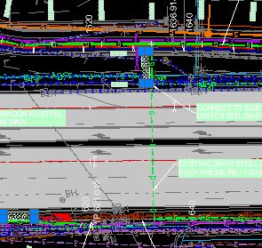
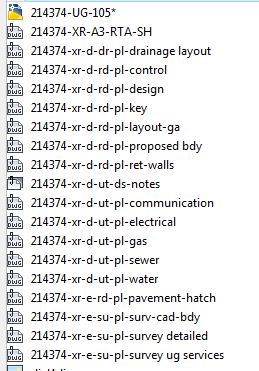
Hi all first of all thanks to everyone for all the help in the past, a really cool community here, hopefully one day i have the knowlede to return the favour. maybe i could shout a six pack of ausie beer some time. I am working on a road design with a whole set of drawings that have about 10 -15 xrefs, for example pavement hatch, contours, detailed survey, cadastral, design, ret walls, drainage layout, survey ug services, tcs layouts, utilities, utilities (current theme), survey bdy, prop bdy, plan control, text notes. this is the order i need the xrefs in, but some drawings have more or less xrefs than others. can anyone suggest a way i could put these in order rather than individually picking a line from an xref and sending it to the back, over and over again? i thought maybe a table where i number the order next to the xref name. Im new to this lisp routine so please be gentle. Cheers Marcus
-
Hi, I would like a program that does the following: 1. Export CAD floor plan to Photoshop. It should always be of a certain canvas size. 2. Export text and dimensions as editable text layers into Photoshop. The text and dimensions should be at the same location in the PSD file as they were in the AutoCAD file. So what I mean is, the text that says Bedroom should be within the 4 walls of that bedroom. 3. Allow conversion of those dimensions (say from mm into inches) and also allow me to specify the rounding amount and number of decimal places before exporting to Photoshop. If there is a script like this available, please point me to it. Or if anyone can write this for me at a reasonable price, please send me a message with your rate. Thank you.
-
Hey guys! I have always come here for answers to my Lisping needs, but now I need to request some help with a Lisp I have been working on for a few days. I created this program that allows you to draw electrical circuits with choices of exposed/concealed conduit, homerun/full run, number/type of wires in circuit, etc. I have the input, wiring and block creation down, but now I just need to figure out how to insert and align the symbols for the different wires along anything curved. The closest program I can find to what I need is LeeMac's Object Align routine, however, it only allows you to select objects as a whole and align the whole to the line, not the individual objects aligned to the curve like you see on electrical wiring plans. I love the preview stuff of LeeMac's program, just need a version where the individual objects are aligned separately as shown in the below images. Lee's: What I need it to look like: LeeMac, is there perhaps a way you could incorporate this into your code as an option to align objects individually at their insertion points? Right now, my code prompts for a point to draw all of the symbols used and the number of them in a straight line. I could then use this updated program to select those symbols and align them to whatever curve I needed too The absolute best way would be to adjust my original code so that after you draw your circuit lines, it shows a live dynamic preview of all the symbols used aligned at their basepoints along the line you want to put them on. But maybe that would be for another day... Unless LeeMac, you would like to check out my code and tweak as needed... ****EDIT**** I figure I might as well go ahead and post up what I have so far. It is working pretty good, except that the first time I choose how many of each to use, it doesn't space the blocks correctly, but then it will afterward. Perhaps people can see what direction I am taking this and offer ideas or improvements to the code to make it work better? MEP Design.zip
-

Looking to *Insert Dynamic Block and rotate Dynamic Grip*
sbrennan85 posted a topic in AutoLISP, Visual LISP & DCL
Ok, so I recently found how I can apply a dynamic rotation to a block, keep the text/attribute positioning relative to the original location, but not actually rotate. It's perfect and I'm excited to implement it in my company. However, I'm also working on a few ribbon tabs that will have a bunch of these blocks (different symbols and/or attributes). Right now I'm simply using macros to insert the block, and bypass any steps necessary for that particular block (scale, rotate, etc). However, with a traditional block I need to use a LISP routine that was created years ago here at our company to rotate the attributes (I think it was created before AutoCAD had the function? I don't know, I've only been using CAD for about 8.5 years). I'm trying to do the following in as much automation as possible: Insert Dynamic Block Scale based on USERR1 value Force rotation to 0 degrees Allow for user input of Attribute(s) Select the (only) Dynamic Rotation Grip Allow for user input of Dynamic Rotation Repeat all of the above until cancelled I'm pretty sure this is only doable via LISP, but I know NOTHING about LISP programming, and was hoping someone could help out. I've attached one of the many blocks I have with this "auto-aligning" text feature. Thanks in advance! SAMPLE.dwg -
Can anybody tell me how and where can I make a routine package I have designed, copyrighted? Thanks in advance
-
Dear cadtutor forum, I am new autolisp user (i use autocad civil 3D 2012), i try to coding there but it doesn't have the "Save All" option in the console. How to save the file i've made? Thank you in advance
-

LISP to move selected objects to a specified layer?
Dan Kitchens posted a topic in AutoLISP, Visual LISP & DCL
Hi peoples, I've got a new challenge: Is there a Lisp that moves selected objects to an exisitng, specified layer? I want to be able to select objects on the screen, type in a short command, and they automatically go to a certain layer (let's call it "Layer 1"). Having looked everywhere on the net, I can't find anything similar, and I don't know enough AutoLISP to be able to write it myself... Thank you in advance! Dan -
I need to create a "pline arc"(Arc option in PLine) and connect a set of blocks. So i m developing a lisp to do it. 1. I get the objects from user using "ssget" 2. I am using COMMAND command to draw PLine arc option to draw pline between the blocks's POSITION property 3. but the COMMAND command has to be closed using [ '') ] 4. But i need to give the next argument iteratively using for loop 5. How to iteratively give the next arguments in COMMAND command THANKS in ADVANCE
-
I'm quite new with the BOM thing with Autocad, though I have used xref a lot. Is there a way to create a BOM or at least a list/table of the xrefs I have attached to the drawing with the number of times used or occurrences in the drawing? The drawing I made have about 50+ xrefs and some of it is attached more than once, if i'm going to use the AMPARTREF, and made a reference on an xref, i have to input the quantity manually. Is there a way to automate this?
-
Alright guys, you're up. I've gotten a lot out of this site, so here's giving back. One thing that AutoCAD refuses to give us (as far as I know) is the ability to copy named views. I work on long projects that can carry over 20 named views and it's a lot easier to work in the cut sheets if the named views are there. Well, here you go. The program will let you create the named views, export them (to a .scr file) and then import that file. It doesn't really import them, it actually recreates them the same way they were originally created. Therefore, the settings may not be how you need them, but the coding can be easily edited. Let's see who can make this better. I'm sure there is redundancy, but it does what I need it to. Also, I can't get the ExportViews it to end clean, it always tells me it's ending with a bad function. I'm sure it's just trying to run a return value, but it works. One other thing, is there a way to run a script quietly? Again, it works, just doesn't look as pretty as it could. There's also no error trapping once you run it. I added a dialog box to remind users of a couple things that will cause errors, but nothing else. So without further ado, here you go: ;;;Code created by Matt Kearney 3/2012 ;;;CreateViews will allow to set a 3 point UCS or use existing and create a new named view ;;;ExportViews will export the data for all named views to a script file to be run in another drawing ;;;ImportViews will run the script file created from ExportViews (technically, it will freeze all layers and run any script file) ;;;THIS PROGRAM IS PROVIDED TO ALL FOR FREE. ANY MODIFICATIONS AND REPRODUCTIONS ;;;ARE ALLOWED. PLEASE GIVE CREDIT WHEN USING OR REFERENCING THIS PROGRAM. THIS ;;;PROGRAM IS OFFERED 'AS-IS' WITH NO IMPLIED WARRANTIES OR GUARANTEES. ;;;Dialog box info from http://www.afralisp.net/archive/lisp/acet-utils.htm and Kerry Brown on CADTutor.net forums ;;;Started with ViewsIO.lsp from www.JTBworld.com (changed almost everything, but thank you still) (vl-load-com) ;CREATEVIEW ;Choose 3 point UCS or keep existing, then window for named view (defun C:CREATEVIEW (/ cview pt1 pt2) (setq v (getstring T "Enter view name to save:")) (setq cview (getvar 'viewsize)) (SETQ reply (ACET-UI-MESSAGE "Create a new UCS?" "UCS" (+ Acet:YESNOCANCEL Acet:ICONQUESTION) ) ) ;; Cancel = 2 ;; Yes = 6 ;; No = 7 (IF (= reply 6) ;;if yes (progn (command "UCS" ;;create a 3 point ucs by picking points 3 (setq pt1 (getpoint)) (setq pt2 (getpoint)) pause "UCS" "S" v ) ;;Sets UCS and saves it (command "plan" "" "_.zoom" "C" (/ (distance pt1 pt2) 2.0) cview ) ;;Rotates view and keeps zoom (close enough) ) (IF (= reply 7) ;;if no (PROGN (setvar "EXPERT" 4) ;;ignore error if named ucs exists (COMMAND "UCS" "S" V) ;;name current UCS (setvar "expert" 0) ;;return expert value to 0 ) (QUIT) ) ;;Quit on cancel ) ;;end dialog (command "_.zoom" "W" (getpoint) (getpoint)) ;;Zooms to view (command "_.view" "S" V) ;;Save view with name provided (command "_.view" "E" "L" v "D" "" "R" v) ;;Makes sure layer state is not saved and restore view created (princ) ) ;;End Create View ;;ExportViews ;;Choose file to export view info to (defun c:ExportViews (/ fn) (setq ce (getvar "CMDECHO")) ;;Insert the following to create a yes/no/cancel dialog box (SETQ reply (ACET-UI-MESSAGE "Do All Views Have A Named UCS?" "Named UCS" (+ Acet:YESNOCANCEL Acet:ICONWARNING) ) ) ;; Yes = 6 ;; No = 7 ;; Cancel = 2 (IF (= reply 6) ( (setvar "cmdecho" 0) (command "layerpmode" "ON") ;;Make sure layerp is set to on (command "_.layer" "OFF" "*" "y" "F" "*" "") ;;Turn off and freeze all layers to run faster (if (setq fn (getfiled "Export views to" (strcat (getvar "dwgprefix") ;;Use drawing name to create script file (vl-filename-base (getvar "dwgname")) "_VIEWS.scr" ;;Add _Views to file name for script ) "scr" ;;use extension .scr 1 ;;Create new file ) ) (ExportViews fn) ;;Run ExportViews as defined below ) (command "layerp") (setvar "cmdecho" ce) (princ) ) ;end Yes Reply (IF (= reply 7) (PROGN (ALERT "Set All Views With A Named UCS Before Proceeding.") ;;"No" response ) ) ;;Do nothing on cancel ) (princ) ) ;;ImportViews ;;Choose file with view info to import (defun c:ImportViews (/ fn) (setq ce (getvar "CMDECHO")) (setvar "cmdecho" 0) (command "layerpmode" "ON") ;;Make sure layerp is set to on (command "_.layer" "OFF" "*" "y" "F" "*" "") ;;Turn off and freeze all layers to run faster (if (setq fn (getfiled "Select Exported Views..." ;;Choose file to import from (getvar "dwgprefix") ;;Start in same folder as current drawing "scr" ;;Make sure it's a scr file 8 ;;(I'm not positive what this does, but it works) ) ) (command "script" fn) ;;Run script provided ) (command "layerp") ;;Return layers to previous state (doesn't always work, too many commands between?) (setvar "cmdecho" ce) ;;Return Command echo (princ) ) ;;;ExportViews programming ;;;This will not work views with a width or height over 1x10^5 units. Add RTOS command to remaining variables if you need it to. ;;;Layer state is not saved with each view (company standard) (defun ExportViews (fn / vx vy vcxw vcyw ucso x1w x2w y1w y2w x3w y3w vcx vcy x1 x2 y1 y2 vqty vlist f vdata ) (while (setq vqty (tblnext "VIEW" (null vqty))) ;;Get View info and run following for each (setq vlist (cons (cdr (assoc 2 vqty)) vlist)) ;;create a list with each view name ) (setq f (open fn "w")) ;;Open scr file for writing (if f (progn (princ "Following views exported:\n") (foreach view vlist (setq vdata (entget (tblobjname "view" view))) (command "_.view" "r" view) ;;Restore view to get info (command "ucs" "NA" "R" view) ;;Be sure UCS is correct and named (setq vy (getvar "VIEWSIZE") ;;Set view height vx (* (getvar "viewsize") ;;Do some math to set view width (/ (car (getvar "SCREENSIZE")) (cadr (getvar "SCREENSIZE")) ) ) ucso (getvar "ucsorg") ;;set UCS origin vcxw (rtos (car (trans (getvar "viewctr") 1 0)) 2 12) ;;set view center x coordinate in world (keep 12 digits to avoid truncated numbers) vcyw (rtos (cadr (trans (getvar "viewctr") 1 0)) 2 12) ;;set view center y coordinate in world vcx (car (getvar "viewctr")) ;;set view center x coordinate in view UCS vcy (cadr (getvar "viewctr")) ;;set view center y coordinate in view UCS x1 (- vcx (/ vx 2)) ;;set left coordinate in view UCS x2 (+ vcx (/ vx 2)) ;;set right coordinate in view UCS y1 (- vcy (/ vy 2)) ;;set bottom coordinate in view UCS y2 (+ vcy (/ vy 2)) ;;set top coordinate in view UCS x1w (rtos (car ucso) 2 12) ;;set UCS origin x coordinate in world x2w (rtos (car (trans (list '10 '0 '0) 1 0)) 2 12) ;;set first UCS x point in world (+10 in x direction) x3w (rtos (car (trans (list '0 '10 '0) 1 0)) 2 12) ;;set second UCS x point in world y1w (rtos (cadr ucso) 2 12) ;;set UCS origin y coordinate in world y2w (rtos (cadr (trans (list '10 '0 '0) 1 0)) 2 12) ;;set first UCS y point in world y3w (rtos (cadr (trans (list '0 '10 '0) 1 0)) 2 12) ;;set second UCS y point in world (+10 in y direction) ) ;;End setq ;;;Write script for each View (princ ";Create View " f)(princ view f)(princ "\n" f) ;;Comment line to state view (princ "(command \"UCS\" \"W\")\n" f) ;;Set UCS to world (princ "(setq vy " f)(princ vy f) ;;Start setq and add variables from above (princ " vx " f)(princ vx f) (princ " vcxw " f)(princ vcxw f) (princ " vcyw " f)(princ vcyw f) (princ " x1w " f)(princ x1w f) (princ " x2w " f)(princ x2w f) (princ " x3w " f)(princ x3w f) (princ " y1w " f)(princ y1w f) (princ " y2w " f)(princ y2w f) (princ " y3w " f)(princ y3w f) (princ " vcx " f)(princ vcx f) (princ " vcy " f)(princ vcy f) (princ " x1 " f)(princ x1 f) (princ " x2 " f)(princ x2 f) (princ " y1 " f)(princ y1 f) (princ " y2 " f)(princ y2 f) (princ " view \"" f)(princ view f) (princ "\")\n" f) ;;End setq (princ "(command \"UCS\" \"3\" (list x1w y1w '0) (list x2w y2w '0) (list x3w y3w '0))\n(command \"UCS\" \"NA\" \"S\" view)\n" f ) ;;create a 3 point UCS and name it (princ "(command \"plan\" \"\")" f) ;;set view to named UCS (princ "(command \"_.zoom\" \"W\" (list x1 y2) (list x2 y1))\n(command \"_.view\" \"s\" view)\n(command \"_.view\" \"E\" \"L\" view \"D\" \"\" \"R\" view)" f ) ;;Zoom window to view coordinates, save view as named, make sure layer state is not saved (princ "\n\;\;\;\n\;\;\;\n" f) ;;End script for view, add comment lines to separate next (prin1 view) ;;List view in command line as exported (terpri) ) (close f) ;;close script file that was being written ) ;;End progn ) ;;End If (princ) ) ;;End ExportViews programming createandcopyviews.lsp (I'm not sure if it's better to write it or attach it, so I did both.) -Matt