Search the Community
Showing results for tags 'offset'.
-
Working through Brian Benton's tutorial 'Quick Run Thru' I find that the 'Offset' command works differently from the way it is displayed. Command: _line Specify first point: Specify next point or [undo]: Specify next point or [undo]: Zero length line created at (3290.0000, 1250.0000, 0.0000) Specify next point or [Close/Undo]: Command: O OFFSET Current settings: Erase source=No Layer=Source OFFSETGAPTYPE=0 Specify offset distance or [Through/Erase/Layer] : Specify second point: Value must be positive and nonzero. Specify second point: Specify second point: Value must be positive and nonzero. Specify second point: Specify second point: Select object to offset or [Exit/Undo] : Specify point on side to offset or [Exit/Multiple/Undo] : The tutorial doesn't say anything about a second point. It just says 'enter o for offset, specify distance to offset, click on the line to offset' -- Bingo, the line is offset. Not in the AutoCAD 2014 I have Can someone run me through how it actually works in 2014. Thanks
-
I'm looking for a LISP that will allow me to offset a polyline on one layer with a global width (any varying width) to another layer (a specific layer written into the code) with a global width of 0. Please help
-

Hatch of Closed Polylines Offset From User Designated Points
doerner posted a topic in AutoLISP, Visual LISP & DCL
I am pretty new to lisps, but I think that I have made this a little more complex than it needs to be. I am trying to create a offset box around a set polyline and then hatch the box. I have succeeded in making it work for four user designated points, but I am looking for more. I would like to be able to run the lisp, draw a polyline with infinite bends and angles, and then have it hatch the resulting offset box. If anyone has any optimization ideas I would love to hear them trench.lsp
-

Offset to layer on particular side and erase orignal object offset from
Baber62 posted a topic in AutoLISP, Visual LISP & DCL
Hi, Need help with this routine, it offsets to a selected layer however I need to add coding to erase the orginal object that it was offset from. The coding is as listed below: [/b] ;; OL.lsp ;; Offset-to-Layer = Offset an entity a specified distance, and Change the new entity to a specified Layer. ;; At first use, offers current Offset Distance and current Layer as defaults; ;; subsequently, offers this routine's previously-used Offset-to-Layer Distance (even if ordinary Offset ;; distance has been changed) and Layer-to-change-to as defaults. ;; by Kent Cooper, August 2008 (defun C:OL (/ offlaytemp offent) (initget 134) (setq offlaydist (cond ( (getdist (strcat "\nOffset-to-Layer distance or [Through] <" (cond ((numberp offlaydist) (rtos offlaydist)) ((= (getvar 'offsetdist) -1) "Through") ((rtos (getvar 'offsetdist))) ); end cond ">: " ); end strcat ); end getdist ); end first cond test (T (if (not offlaydist) (getvar 'offsetdist) offlaydist)) ); end cond offlaytemp (getstring (strcat "\nLayer to Offset to <" (if offlay offlay (getvar 'clayer)) ">: " ); end strcat ); end getstring offlay (cond ((/= offlaytemp "") offlaytemp) (offlay) (T (getvar 'clayer)) ); end cond ); end setq (while (not (while (not (and (setq offent (ssget ":S" '((0 . "LINE,ARC,CIRCLE,ELLIPSE,LWPOLYLINE,SPLINE,XLINE,RAY")))) (= (cdr (assoc 70 (tblsearch "layer" (cdr (assoc 8 (entget (ssname offent 0))))))) 0); 0 for Unlocked, 4 for Locked ); end and ); end not (prompt "\nSelected Entity cannot be Offset, or is on a Locked Layer; try again: ") ); end while ); end not (command "_.undo" "_be") (command ".offset" offlaydist offent pause "" ".chprop" "l" "" "la" offlay "" ); end command (command "_.undo" "_e") ); end while ); end defun (princ "\nType OL to Offset to Layer.") (princ) [b] Any help would be appreciated. -
1st Post, woot woot. I searched through many of the existing forums but couldn't find one that addressed this issue... I work a lot with polylines, to create design contours. I usually have a contour at the bottom or top of a hill, then I use the 'offset' command to offset the line to conform to a 3:1 slope as far as I need, to tie into the existing topo. My problem is, after offsetting all these plines, they are all at the same elevation as the original line. Is there a faster way to change the elevation than clicking on a line, entering the elevation in the properties window, clicking on a new line, wash-rinse-repeat? This is very tedious, especially with 20+ offset lines each time. Or is there a way to offset with increasing/decreasing elevations each time? Thanks
-

Offset a line without input from user(prompting)
avinashg posted a topic in AutoLISP, Visual LISP & DCL
Hi All, I am new to this forum and lisp. Trying to create cross sections of drain using lisp.The details of are fed from excel for each cross section.I am stuck as I was not able to figure out the way to offset line/polyline by selecting the lines and offset distance from the program itself. Any help would be appreciated. Thanks in advance. Cross SectionOf EWE H-100ch 0 to 575m.dwg read_excel_data_to_array.lsp drain.xls I have grabbed the code given by Fixo to read data from excel (http://www.cadtutor.net/forum/showthread.php?41910-Read-Excel-Data-Cells-and-Draw-in-AutoCAD-thru-LISP/page2). Thanks Fixo. -
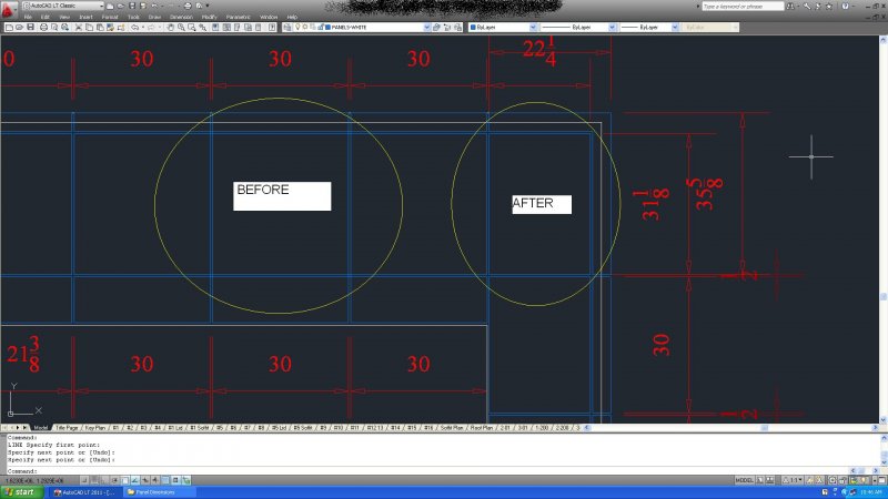
Hello Everyone, I'm quite new with autocad, and I'm trying to automate more of my work so I can finish it quicker. Any different suggestions would also be appreciated! Please see attached picture! I am currently recieving site dimensions for framing, my job is to reproduce (using isometric views) these framing dimensions in Autocad (framing is color coded white) and add metal panels (color coded blue), ultimately creating the panel dimensions to be sent to the panel manufacturer. Once I reproduce the framing dimensions I use a method of several offsets and construction lines to create my panels. My problem: each metal panel needs either 5/8" or 1/2" spacing. I am consuming a lot of time using the trim command and individually clicking out all the little squares. see picture. I like using QDIM quick dimensions to easily seperate spacing and panel dimensions, so trimming out the panels (as far as I know) is a must. Suggested solution: Is there a way I can tell autocad to cut out all 1/2"x1/2" or 5/8"x5/8" squares? As always, if you have different suggestions I am open to them. Thanks in advance for any replies! EDIT: I am using autocad 2011 LT, so I can't run script things..
-
Hi All, I need some help i have three lisp routines that i would like to combine into one routine. they all use the same objects to get their results so i was wondering if there was a way to combine them together. the order of would be as follows: 1. olo (Offset Polylines) 2. exl (Extrusion Lengths) the only that i see with this one is that it requires use input for placement, i would for it to place the results to the outside of lines. run the lisp routine by creating a rectangle exploded to see what it does. 3. pte (Panel Tab Extension) They all run perfectly by themselves, but im just trying to speed up the process. Here are the codes that i'm using. any help would be appreciated. Thanks, Brian ;| OFFSET POLYLINES [email="mfuccaro@hotmail.com"]mfuccaro@hotmail.com[/email] September 2003 |; (defun c:olo( / plines ; selection set of polylines ext ; extrnal point dist ; distance to offset poly ; a polyline from plines plist ; the list of poly del ; polyline to delete int ; internal point i) (command "undo" "begin") (princ "select polylines") (setq plines (ssget) i 0 ext (getvar "limmax") dist (getdist (strcat "distance <" (if olddist (rtos olddist) ;use old value as default "") ">"))) (if (not dist) (setq dist olddist)) ;reuse old distance if user press <Enter> (repeat (sslength plines) (setq poly (ssname plines i)) (setq plist (entget poly)) (command "offset" dist poly ext "") (setq del (entlast) int (polar (cdr (assoc 10 (entget del))) (angle (cdr (assoc 10 (entget del))) (cdr (assoc 10 plist))) (* 2 (distance (cdr (assoc 10 plist)) (cdr (assoc 10 (entget del))))))) (command "offset" dist poly int "") (command "_.change" (entlast) "" "_p" "_la" (getvar 'clayer) "") (entdel del) (setq i (1+ i))) (command "undo" "end") (setq olddist dist) ;preserve current distance for next run (princ) ) ;Extrusion Length (defun c:EXTL (/ cEnt tStr tBox tHgt tWid gr sPt cPt lAng bPt tPt pt1 pt2 pt3 pt4) (vl-load-com) (if (and (setq cEnt (car (entsel "\nSelect Object: "))) (member (cdr (assoc 0 (entget cEnt))) '("LWPOLYLINE" "POLYLINE" "LINE"))) (progn (setq tStr (strcat "1@" (rtos (- (vla-get-length (vlax-ename->vla-object cEnt)) 4.0)) (strcat "''")) tBox (textbox (list (cons 1 tStr) (cons 40 (getvar "TEXTSIZE")))) tHgt (- (cadadr tBox) (cadar tBox)) twid (- (caadr tBox) (caar tBox))) (princ "\nPosition Text...") (while (eq 5 (car (setq gr (grread t 5 0)))) (redraw) (if (listp (setq sPt (cadr gr))) (progn (setq cPt (vlax-curve-getClosestPointto cEnt sPt) lAng (angle cPt sPt) bpt (polar cPt lAng (/ (getvar "TEXTSIZE") 2.)) tpt (polar bpt lAng tHgt) mPt (polar bPt lAng (/ tHgt 2.)) pt1 (polar bpt (+ lAng (/ pi 2.)) (/ tWid 2.)) pt2 (polar bPt (- lAng (/ pi 2.)) (/ tWid 2.)) pt3 (polar tpt (+ lAng (/ pi 2.)) (/ tWid 2.)) pt4 (polar tPt (- lAng (/ pi 2.)) (/ tWid 2.))) (grvecs (list -3 pt1 pt2 pt3 pt4 pt1 pt3 pt2 pt4))))) (if (eq 3 (car gr)) (progn (setq lAng (- lAng (/ pi 2.))) (cond ((and (> lAng (/ pi 2)) (<= lAng pi)) (setq lAng (- lAng pi))) ((and (> lAng pi) (<= lAng (/ (* 3 pi) 2))) (setq lAng (+ lAng pi)))) (Make_Text mPt tStr lAng)))) (princ "\n<!> Incorrect Selection <!>")) (redraw) (princ)) (defun Make_Text (pt val rot) (entmake (list (cons 0 "TEXT") (cons 8 (getvar "CLAYER")) (cons 62 1) (cons 10 pt) (cons 40 (getvar "TEXTSIZE")) (cons 1 val) (cons 50 rot) (cons 7 (getvar "TEXTSTYLE")) (cons 71 0) (cons 72 1) (cons 73 2) (cons 11 pt)))) ;;; PANEL TAB EXTENSIONS (defun c:PTE(/ lSet actDoc lDel doMode objLst) (vl-load-com) (princ "\n>>> Select lines to extend/reduce <<< ") (if (and (setq lSet (ssget '((0 . "LINE")))); (setq lDel (getreal "\nSpecify : ")) ); end and (progn (initget 1 "Positive Negative Both") (setq doMode (getkword "\nSpecify direction [Positive/Negative/Both]: ") objLst(mapcar 'vlax-ename->vla-object (vl-remove-if 'listp (mapcar 'cadr(ssnamex lSet))))); end setq (vla-StartUndoMark (setq actDoc (vla-get-ActiveDocument (vlax-get-acad-object)))); end vla-StartUndoMark (if(member doMode '("Negative" "Both")) (foreach ln objLst (vlax-put ln 'startpoint (polar (vlax-get ln 'startpoint) (vlax-get ln 'angle)(- lDel))); end vlax-put ); end foreach ); end if (if(member doMode '("Positive" "Both")) (foreach ln objLst (vlax-put ln 'endpoint (polar (vlax-get ln 'endpoint) (vlax-get ln 'angle)lDel)) ); end foreach ); end if (vla-EndUndoMark actDoc) ); end progn ); end if (princ) )
-
Hi All, I have the wonderful Lisp routine that mfuccaro wrote back in 2003 called Offset Polylines "POF" for short. like I've said before in my other threads I'm just learning how to write and modify Lisp routines, I've manage to modify this routine to offset to the current layer but i can't figure out how to get it to remember the last offset distance. Can anyone help me please. thanks, Brian ;| OFFSET POLYLINES mfuccaro@hotmail.com September 2003 |; (defun c:pof( / plines ; selection set of polylines ext ; extrnal point dist ; distance to offset poly ; a polyline from plines plist ; the list of poly del ; polyline to delete int ; internal point i) (command "undo" "begin") (princ "select polylines") (setq plines (ssget) i 0 ext (getvar "limmax") dist (getdist "distance ")) (repeat (sslength plines) (setq poly (ssname plines i)) (setq plist (entget poly)) (command "offset" dist poly ext "") (setq del (entlast) int (polar (cdr (assoc 10 (entget del))) (angle (cdr (assoc 10 (entget del))) (cdr (assoc 10 plist))) (* 2 (distance (cdr (assoc 10 plist)) (cdr (assoc 10 (entget del))))))) (command "offset" dist poly int "") (command "_.change" (entlast) "" "_p" "_la" (getvar 'clayer) "") (entdel del) (setq i (1+ i))) (command "undo" "end") (princ) )
-
Hi ALL, You know how when you offset a rectangle it it stay as a polyline? i need a lisp routine that i can use to offset the rectangle, set the new lines to current layer, and substract the offset distance from both end of the line. i know thats asking alot but has anyone seen a routine like this? Thanks, Brian
-

How to move some vertices of a solid to the offset of solids edge?
liepa posted a topic in AutoCAD Beginners' Area
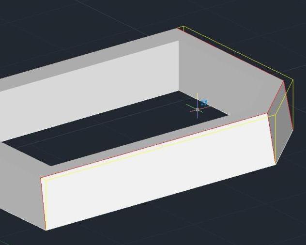
Hello everybody, 1) I have a solid with vertical walls. I need a solid, were some walls ar not vertical. So I need to move some vertices to the offset of top edge. Please, check a pic. (yellow edges have to be were are the red ones). I did it with construction lines, but I'm sure there is a more efficient way (with a command like offset). 2) Can I offset just a part of the solid at all? Thank you for any ideas
-

Inserted block begin at end of a pline instead of the beginning
jremiro posted a topic in AutoLISP, Visual LISP & DCL
I have a lisp routine that we have used for several years. The routine takes a pline, offsets it on either side based on user defined spacing then inserts a premade block to symbolize a road. The block is spaced according to user defined spacing. For instance, a block can be inserted at 2 times the width of the "road" as many times as needed to symbolize the entire length of the offset pline. Hopefully this makes sense! This lisp routine works great on it's own. However, once inserted into a macro, it starts the block insertion at the end of the pline, only inserting one block. This is happening in all versions of AutoCAD we are using from 2004 through 2011. Is there a setvar that should be reset or cleared within the lisp routine? Any suggestions would be appreciated. Thanks! -
Lines snap at an offset distance (0.0000274 m e.g.) from the actual point. What change of settings can resolve it?
-

Offestting lines multiple distances in one command?
fisher22 posted a topic in AutoCAD Beginners' Area
Hi, I'm literaly just starting to use CAD so this might be a silly question, but how would I offset a line more than one distance in a command? Is there like a symbol you put between each distance like 2000;2250;2650 or something along those lines (no pun intended). Again sorry is this is a silly question. thanks -
I have done a fair amount of scouring the internet for a solution, to no avail, hopefully someone here can help me. For example, I have a hosted electrical receptacle device with a loaded annotation (2D symbol for printed plan purposes). What I would like to do is add a horizontal annotation offset that allows me to move the symbol left OR right based upon a single properties window field. As it sits right now, I have a reference line to one side of my device center line that is tied to a dimension parameter. Unfortunately Revit does not allow negative lengths, which means moving the annotation in the opposite direction is not possible. I have even tried (without expecting it to work) locking my annotation to two different reference lines (a right and a left parameter), but this produces no change at all. I believe this is because it can't be locked to two parameters, with different values, at the same time. One of the threads I read (http://www.revitcity.com/forums.php?action=viewthread&thread_id=15532) makes mention of this functionality, but does not go into detail on how to make this happen. Given that this thread was quite old, I did not ask this question on that forum yet, but I might. Any help you can give is much appreciated. FYI.. I am using Revit MEP 2011.
-
Hi, I'm new to writing LISP's and have finnished a couple for my studio. Just to keep busy when tides are low. The last I'm almost done with is an offset lisp that offsets in sequence (I do't really care if there are lisps already made for this, I've been trying to practice on my lisp routine making). I first choose the number of offsets, then the value for each offset and finally the side to offset. My problem is that when I zoom in close to the line the lisp works great - I mean, it offsets to the valeus I inputed. But when I'm a bit far out on the zoom it offsets to different values. I really don't know why it is doing this. Do I need to adjust the zoom sesitivity or something? Is there such a thing? Here is the code I wrote (it's in portuguese). Don't mind the messy way it's wirten. Thanks ;Criado por Rodrigo Líbano (defun c:offseq (/ numof numof2 numof3 list carl carls carlss voffx vof2x vof1x p2x side) (initget 7) (setq numof (getint "\nNúmero de offsets [2 ou mais]:")) (initget 7) (setq voffx (getdist "\nValor do primeiro offset:")) (setq numof (- numof 1)) (setq numof2 numof) (setq numof3 numof) (setq list (cons voffx voffx)) (setq vof1x voffx) (while numof (initget 7) (setq vof2x (getdist (strcat "\nValor do próximo offset [Restam:" (rtos numof 2 0)"]:"))) (setq vof2x (+ vof2x vof1x)) (setq list (cons vof2x list)) (setq vof1x vof2x) (setq numof (1- numof)) (if (= numof 0) (setq numof nil) (setq numof numof) ) ); end while (princ list) (setq carlss carls) (while (setq p2x (cadr (entsel "\nSelecione Objeto:"))) (setq side (getpoint "\nSelecione lado:")) (while numof2 (setq carl (nth numof2 list)) (if (= numof2 numof3) (setq carls (- carl carl)) (setq carls (nth (+ numof2 1) list)) ); end if (setq carls (- carl carls)) (setvar "OFFSETDIST" carl) (command "._UNDO" "_GROUP") (command ".OFFSET" carl p2x side "") (if (= numof2 0) (setq numof2 nil) (setq numof2 (- numof2 1)) ); end if ); end while (setq numof2 numof3) (setq carl carlss) ); end while (princ) )
-
Hello everybody, I need your help again. From a line, how can I make an offset to both sides? Thank you all! Rodrigo
-

Rasters being shifted to wrong spot when laser cut
justinpod posted a topic in AutoCAD Drawing Management & Output
Hi, I am using autocad 2011LT to plot to universal laser cutters. We have three different lasers: M300, M360, and V460. When we plot rasters to the M300 and V460, we often notice a shift in the raster cuts from the vector cuts. All of the rasters are always shifted in the same direction and by the same distance (anout 2-3 mm). This shifting started happening about 6 months ago. We have not noticed this shift yet in the M360, but believe it has something to do with the autocad settings. We have cleaned out and reinstalled all of the laser cutter drivers and still have this issue. Has anyone ran into this issue or have any advice? -
I'm looking for a way to produce a tapered offset in AutoCad 2008 (a simple linear taper will do for a starter), perhaps by specifying starting and ending offset distances to be applied along the length of a selected arc, polyline (2D) or spline. I'm thinking that this will probably require some code, although it seems like this might be a fairly common requirement, such that there would be an existing solution that I just haven't gleaned as yet. Thoughts?
-
Hi, I've been struggling with my z purlins as I am jack of copying. so I've created a dynamic block BUT I don't know how to create a custom Column Offset (in the properties box) but only manually set it in the distance1 properties. I'm thinking that it needs some lookup or something. ARRAY_ARGH1.zip

.jpg.731acfd6e202719c10ebf8773185a986.jpg)