Search the Community
Showing results for tags 'rotate'.
-

Can I synchronize three separate rotations in a dynamic block?
numberOCD posted a topic in AutoCAD 2D Drafting, Object Properties & Interface
Morning, I'm working on a block with a few variables I'm trying to synchronize. I've worked dynamic blocks in the past for mirror imaging stretches, but is there a way I could sync it so when I rotate Rotation Parameter 1 10 degrees, that Rotation Parameter 2 and Rotation Parameter 3 rotate the same 10 degrees? Thanks for the help! -
Hi, How can I rotate a Spur Gear as you can see on the picture. http://s3.postimg.org/wbwxx2soz/rotation.png Thank you
-
Hi all, I have to modify and rotate assemblies very very often on a daily bases. Copy one assembly to a new location, and I have to modify it and then change the angle (I make a model for pipelines and cable-lines . Often there is a similar part with different slope for next segment.) What I do: - Select assembly parts (in Advance Steel I have a custom command assigned) - input R for rotate - select the base point for rotation - enter R for reference - select the same base rotation point as before - select second point for reference - select the new point on target line (instead of typing angle) Is there a macro or something which could allow me to - select assembly parts - start the command - pick 3 points for rotate: base point, point on start line and point on target line? It looks similar, but if I do this 100 times a day, and in a routine forget to select the second time base point or similar... I have searched (not enough, obviously) , but most of Rotate macro/lisp are for text / block - I need it for multiple objects (using Advance Steel on ACad platform). From some toppics discussing Rotate I got an impression that Macro can't do it... Thanks in advance, cheers
-

Dynamic Block - Rotate/Stretch along a linear path.
dblclkmatt posted a topic in AutoCAD Drawing Management & Output
Hello CADtutor, First time post, long time reader. Huge fan. I tried to find this problem on the forum before posting, but had no luck. I am trying to have a dynamic block that will show the profile of a steel plate, detailing the angle of a bevel. Including the plate thickness, the land, gap and the actual angle of the bevel. I've gotten most of it figured out, but having a grip to SET the angle at a specific number, while maintaining the drawing's integrity is proving difficult. I have attached the block I have created so far (minus the previous attempts to rotate the beveled angle). BVL_detail.dwg The basepoint of the rotate parameter should be at the junction of the bevel & land. I need it to stay connected to the end point of the top-most flat line as it rotates, which means the lines need to stretch to match the changing angle. It will either rotate that line along with it, or if I apply a stretch tool, it gets all disconnected and just plain wrong. One of the things I am liking about my current set up is I can grab a grip, and then type the number I need and it will pop on into place. Was hoping for the same effect if I typed in the angle, it would be exactly that, while also adjusting the drawing. I'm hoping to get some direction of things to try, or a straight solution. I've been tweaking with it for the better part of the day and finally conceded to ask for help. Even alternate solutions would be greatly appreciated. My first attempt was to have prompts that ask me for the details, and after I answered them all, it would just makes the detail for me. But that's some super secret CAD magic I just don't possess yet. If clarification is needed at all, please let me know. Thanks in advance! -

What does "Radius of parameter" do?
Vagulus posted a topic in AutoCAD 2D Drafting, Object Properties & Interface
I am attaching a rotate parameter and action to a dynamic block. I get the "Specify base point" bit okay but I can't figure out what "Specify radius of parameter" does. Do I have to include or exclude other parameters like Flip or Stretch? I get some weird results when I rotate an object with other parameters. Is it possible to place the Grip in a specific place? It always seems to like to sit on top of another parameter name. Thanks -

RO using Ortho not set at 90d increments
Jeffrey NYC posted a topic in AutoCAD 2D Drafting, Object Properties & Interface
I've looked everywhere to find out if there is a setting I inadvertently changed when using Rotate. Whenever I want to rotate an object, and move my mouse up, down, right, left, it not rotating in 90 increments but at 49d26'7.3" I don't know how that happened but I cannot figure out how to reset it back to normal. Does anyone have a clue? I can restart in a new template, but I'e drawn so much that when I copy and paste, it brings that setting in. It's making me crazy! Thanks for any help you can give me. -
Hi there, I have multiple elevation labels that are all reading horizontally. I would love to be able to rotate them individually so that they are flush with my property lines or back of curbs, etc. I know I can change the rotation in the style but I'd hate to make a whole bunch of different styles. I don't really want to explode them, I want them to remain a elevation and upadte as soon as my surface changes. I've read some forumns on this which says you can't do it, but they were from 2005, 2006 time and I'm sure I've seen it done before. Is it possible? Or if anyone else have a suggestion on an alternative, that'd be great.
-
Hopefully I can describe this clearly, here goes.. I have a face-based family that references an annotation family. I have already been able to shift create the annotation shift function, that allows the symbol to move independent of the 3D object (moving the annotation along a wall while leaving the 3D object in place). But now I need to add the ability to rotate that annotation as well (again, independent of the 3D object). This will be used for a camera device to simulate view direction of that camera. I have been able to figure out what is needed to rotate the annotation, but when I try to apply both the shift and rotate functions it over constrains the file. Currently, I have a ref. line that creates the shift function and another that creates the rotate function (both work independently from one another). But, since one of those lines is not always parallel to the other, I cannot lock one line to the other. What I seem to need is the ability to lock an end-point of a ref line / level to the end-point of another. This should allow the shift function as well as the rotate function I need. Does anyone know of a way to do this that I may be missing? Thanks,
-
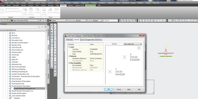
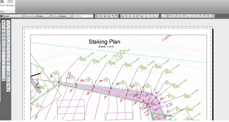
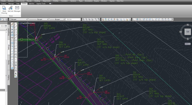
Hi All, I have a dwg that looks great in modelspace, however I created a couple paperspace layouts and then used AlignSpace to rotate to those views. The problem is that my point label style rotates the point labels based on the alignspace rotation. I looked into the point label settings and changed the orientation reference to the World Coord. Sys., but it does not help the points rotate correctly. (world reference is the goal) Any thoughts? Please see attached images.

-
I've tried both draging an image into Autocad and importing it in as a block. When I try to rotates the image it either rotates around a point (but doesn't actually rotate itself) or rotates and disappears only leaving a white outline. How can I properly rotate an image?
-

How can I rotate an uneven circle but restrict the rotation to the circle?
stormist posted a topic in Rigging & Animation
Basically I'm trying to rotate a slot-machine like spinner. I want to restrict the rotation where what is being rotated is the outer skin - the spinner itself shouldn't change position at all. I've tried various pivots but all of them move the actual circle. Here is a couple of angles of what I'm working with: http://i.imgur.com/0sa5j.jpg The only visible part will be in front of the teal plane. Is there a way I might rotate the spinner but constrict the rotation to the space occupied by the spinner? I hope that makes sense. Thanks for any input!! -
I'm trying to rotate this TIN surface, but it won't rotate. I select it, do the ROTATE command, pick the rotation while seeing the how the surface will look, click, and nothing happens. An alignment won't rotate either. The polylines I just made will rotate though. Anyone know what might be going wrong? EDIT: The items that won't rotate are data references. I assume that's why they won't rotate. There must be something extra I need to do to rotate them?
-
Greetings all, i work with AUtoCAD MEP and use "devices" regularly. We normally convert the consultants electrical blocks to devices and do what we do but on this project half of the the consultants blocks are mirrored. The problem occurs when the conversion to MEP device happens. The devices are created 180 degrees out of rotation from the original block. This means the roughly 1200 devices of 20 different types need to be manually rotated. Ugh! I saw this thread below which is the closest i have found to a solution. http://www.cadtutor.net/forum/showthread.php?54913-Rotate-multiple-blocks-around-their-individual-origin-point I dont know LISP other than a minor tweak here and there. What im hoping someone has is a LISP routine the cloely does the following. Select blocks with negative "x" scale get rotation value "RO" get scale value "SC" While there are blocks with a negative "x" scale invert scale rotate 180 degrees relative to original rotation value"RO" Thanks for you time all!
-

Move identically all object in drawing over 100 files
yui009 posted a topic in AutoLISP, Visual LISP & DCL
dear, all due to new geo-reference point introduced to project, we need to move all object in drawing identically over 200 files. is there any way to make it batch and automatize the process including insertion of new ucs cordinates? any opinion is well come. thank you in advance. -
Hello I cannot rotate geo in a sketch to an exact dimension. I am only allowed to move it by hand or mouse. When I type in 36 deggrees it does nothing. What eactly is it that I need to do that I am not being told? I select rotate button while in a sketch I select the geo I tell it x 0 y 0 for center point ( since it will not allow me to pick the z axis) then it will only allow me to move the geo by mouse nothing more exact than that. Is this really how the software is suppose to work or am I missing an important step? Is there a reason why you cannot use the z axis for your rotation center point when rotating geo in a sketch? Thank you