Search the Community
Showing results for tags 'text'.
-

Text 2 MText - Multiple instances
SAFeSTeR posted a topic in AutoCAD 2D Drafting, Object Properties & Interface
Another recent text issue from myself... OK, so recently I discovered the TXT2MTXT command and how wonderful it is, but there is one thing missing which would help me out a lot. Is it possible to change multiple texts, but separately WITHOUT having to re-issue the command? I've experimented with some of the in command options, but unless I'm missing something, nothing seems to work. Preferably, I would like it to work like the FILLET -> Multiple command, so I could select a group of texts, convert them then select another group etc, but the 'multiple' option in TXT2MTXT does not work in such a way. So, am I missing something or is there a LISP routine that can help? Thanks in advance. -
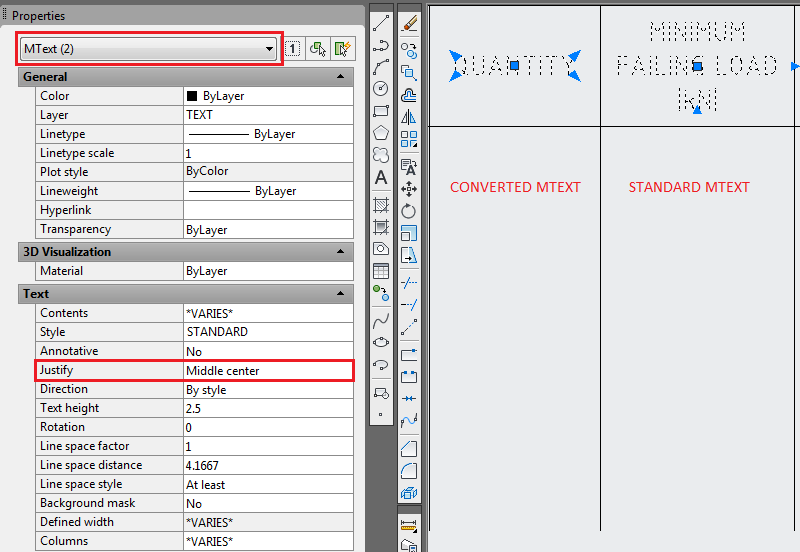
Hi, I've noticed in AutoCAD 2012 that the MTEXT grips have changed, for example, MTEXT justified to 'middle centre' displays just 3 grips, one centrally for moving and 2 'arrow' style grips for stretching. In previous versions of CAD which I used, the MTEXT would have 5 grips, the additional 2 giving more versatility when placing text. However, when using the TXT2MTXT command the resulting MTEXT will display 5 grips (see image). What I would like to know is if it's possible, perhaps with a system variable, for normal MTEXT to display 5 grips as standard as mentioned above? I've searched the help files and the forum but have found nothing... Thanks

-
I have some (single box)tables in my drawings that are referencing measurements on my drawing (Insert field:Object:Measurement). Sometimes I have a formula (ie. =measurement+.250) When I initially enter the text/formula, everything works great. When I go to edit (change what dimension I'm referencing, or modify the formula), the text is invisible. I can highlight where the text/formula is, but I can not see what the text says. If I save and reload AutoCAD, the text is there, until I change it, and then again, it disappears if I want to again modify the text. This is driving me nuts when I need to make multiple edits...ideas? Using AutoCAD Mechanical 2011 and Windows 7
-

Strikethrough Text Option in AutoCAD 2013
hcostanzo posted a topic in AutoCAD 2D Drafting, Object Properties & Interface
I've read about the new option in Text Editor to be able strike through text in Multiline Text, but when I upgraded to 2013 I did not have the option. When I search the help section it explains what the strikethrough text style is but not how to add it to my Text Editor ribbon. My understanding is that it should be a button in the Formatting Pallet under the Underline button, mine just shows Background Mask there. When I expand the formatting pallet I don't show a strikethrough option there either. Does anyone know how I can get it to show up or is anyone having the same problem? Thank you in advance! -

Scaling text in an xrefenced drawing
CADexpert2be posted a topic in AutoCAD Drawing Management & Output
I'm a newbie to AutoCad, I'm currently using Autocad 2012, does anyone know how I can scale a text in viewport whose drawing was referenced in the model view. Please any help will be appreciated. fyi the referenced drawing is a survey drawing. Thanks to all in advance -
I am currently trying to make a bracelet with text engraved in the outside of it with autocad, and my current problem is that I have to make the text 3D before I can subtract it from the bracelet. I am using autocad for mac, which means I dont have the express tools, most notably textexp. I am fairly sure that, without other programs, making 3d text with autocad for mac is impossible. I have tried making text in adobe illustrator, outlining it, and exporting it to autocad, but when I explode it (with the default explode command) and extrude the text, it looks like this: As you can see, very few of the letters get properly extruded, and some arent even effected at all. I've tested other fonts, and they all have the same problem, albeit with some differences in exactly which letters are changed. Except papyrus, in which none of the text gets extruded If anyone knows how to make outlined text from illustrator extrude properly, be my guest! The same goes if you have a different way to make 3D text. All help will be appreciated.
-

find midpoint btw 2 user points - then place user defined text at this midpoint
BudPerry posted a topic in AutoLISP, Visual LISP & DCL
I need to create a routine that will allow a user to pick two points (via intersections) and then it will automatically place text (user types in) at the midpoint between these first two points. So far I have: (defun c:textplacer () (command "_textstyle" "standard") (command "_textsize" "6.0") (command "_osnap" "Intersection") (setq pt1 (getpoint "\nSelect First Point:"));gets the first user point (setq pt2 (getpoint "\nSelect Second Point in POG Direction:"));gets the second user point (setq pt3 (abs (- (car pt1)(car pt2))));gets the middle point btw pt1 and pt2 ;need the rest here );end function Not even sure if pt3 is really getting the midpoint...I'm out of my depths here. -

Text Changes Font When Editing
uuoo10levi posted a topic in AutoCAD 2D Drafting, Object Properties & Interface
I click to edit the text on screen it will change it to another font. It's not doing this every time but pretty often. Anyone have any ideas? -
When I export a section of a drawing using a viewport in paper space and the export pdf function, the text doesn't appear in the PDF. I've noticed some other layers didn't appear, but that was because they weren't set to print. The text layer is set to print, but it doesn't. Anyone know what the problem might be? Thanks.
-

Cannot Print Colour, Crunched up Text, Restricted Print Field
D1-Xen posted a topic in AutoCAD Drawing Management & Output
I am attempting to do a preview print test of my AutoCAD drawing which I have made: SOLA4012 Pluto205.dwg 1. I cannot seems to print it in colour. Can someone tell me what I am missing? 2. My printing into PDF seems to be restricted by the dashed lines. How can I remove or expand this area? 3.The texts are also very crunched up and not as clear as AutoCAD. I am using the: DWG to PDF.PC3 setting > Paper Size ISO A4. How can I fix these output issuses? Many thanks! -
Hi there. I've created a .cui file for my business unit, but I'm having an issue which I'm not sure how to solve. I have created a pull down with text scales and dims scales, so depending on the scale of drawing you are using, you will always have a uniform text to use. (Annotative text can't be used due to client restrictions). Now, I originally had the text set to romanS, but upon a discussion, we now need to use arial narrow. It looks better and takes up less room, apparently. CAD doesn't have an SHX file for this, so I have used the Windows TTF and renamed it to arialn, as that is the system name for it, but when reloading the .cui with this simple text alteration, it has reduced all my custom icons to clouds with question marks, and will only give me text in arial, not arial narrow. If anyone has had an issue like this before and knows of a solution, please let me know. I would be very grateful. Thank you.
-
Hi, I know I've seen some articles on this issue in the past, but I had trouble finding solutions on Links instead of Tables. I have 2 to 6 tables per drawing, each at a maximum of 48 cells. I linked them through the special paste and expended them so each cell is 6" Wide and 1" Tall (in model space) and seen through a viewport at 2" = 1'-0" (so 1" wide by .167" tall). The text is noticeably fuzzy and I'm trying to clear it up without going back to the Tables (the reformatting of the Tables already spent an extra 2 hours on one of the 11 assignments). Any advice is appreciated.
-
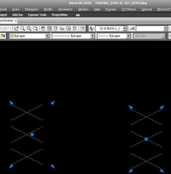
As this has probably been discussed before, I'm stuck and pulling my hair out...lol the text on the right is middle-align, prefect, the text on the left is also middle-aligned but is offset. How can i fix the left text to match the right? Thanks, BW Deen
-

How to control text direction for right-to-left languages?
khoshravan posted a topic in AutoCAD General
I am typing in Farsi which is a right-to-left language. What I see in the monitor is correct. Words appear from right-to-left. But when I print, Entire sentence appears from left-to-right. How can I solve this problem? This happens even if I print to PDF file. So it is not a problem with printer. -
I am having trouble trying to add text to a dynamic block that will stay locked and centered when I stretch it left/right and up/down. The default text I am looking to have should be 36x24 (36 is the lenght of the unit, 24 is the depth). Does anyone know if this is possible to do? I can also upload my block if it helps. Thanks, Art
-
Hello everyone, this is my first post on here and am hoping that someone can help. I have been using Autocad 2012 for a while and last week it became intolerably slow resulting in me uninstalling it and reinstalling it again. This solved the problem and it returned to normal, however, now when i enter multiline text it is always slanted to the right as if it is written in italics. I cannot figure out how to solve this without setting the oblique angle to -11.6 to get it straight again. all other systems running cad 2012 are fine, and when i open an existing drawing with text in, it automatically displays it slanting but then appears normally again when it's opened on the other computers. If anyone could help i'd be really grateful. Thanks Jack
-
Hi All, I'm looking for a routine that when i select the text it would create a layer with the text as it's name. i.e text (S7) = layer name is S7. thanks Brian
-

How to find Vertical Effect is ON in Text Style
Ahankhah posted a topic in AutoLISP, Visual LISP & DCL
Hi everybody, as most of you know, vla-get-TextGenerationFlag function returns a number showing the condition of Upside Down and Backwards toggles inside Effects region of STYLE command's dialog. How is it possible to find out whethere Vertical toggle is ON or OFF? -

Cursor text boxes not displaying...Please help!
SchecterDamien posted a topic in AutoCAD 2D Drafting, Object Properties & Interface
I'm starting a new drawing in Civil 3D 2012 and when I go to draw a line I can't see the small text boxes that show up beside the cursor that allow you to input numbers. I like to type my lengths and angles into these boxes to draw my lines as it makes it 100% accurate however the aren't showing up. Drawing lines is essentially useless because I now have to eyeball it. Is there a keyboard shortcut to get these boxes to display again? Please help. -
I have made a program that will draw objects from user input. I offer a simple sample below that will place a dimension on an object. After the DIMLINEAR line I would like to be able to edit the text of the last dimension with the next (4) possibilities (that I will independently use as needed, no need for optional prompt for condition): 1. \XABC ~ for text under dimension 2. ABC ~ for text on same line after dimension 3. ABC ~ for text on same line before dimension 4. ABC 4'-0" ~ for adding text and HARD coded dimension (actual dim replaced) (defun c:bdt () (SETVAR "CMDECHO" 0) (SETQ STP (GETPoint "\nPick Starting Point: ")) (SETQ P2 (POLAR STP (* 2 PI) 5.0)) (SETQ P3 (POLAR P2 (* 3 (/ PI 2)) 5.0)) (SETQ P4 (POLAR P3 PI 5)) (COMMAND "LINE" STP P2 P3 P4 STP "") (COMMAND "DIMLINEAR" STP P4 "@36.0 ? (PRINC) ) I DO NOT know any VLisp and have been searching books and online content with only similar luck. I have found samples that prompt the user to pick a dimension, but, I have many dimensions I want the PROGRAM to create and EDIT each dim at run time. No user interaction. Please help me with the (4) different scenarios I have using the code I have provided. Please, no bells & whistles, will be above my level of experience at this moment. Thanks for any help.
-
1. How does the stretch command work? I'm trying to scale an object solely in the Y-direction. Is making a block out of all the objects I want to scale the only way to do this? 2. I have a few blocks that I want to make icons for so that I can just click them from the ribbon. Is this possible? 3. How can I set text defaults? i.e. I'm inserting a lot of multi-line text and I always want to justify it MC (middle center) but the default is TL I believe, is there anyway to change this? Thanks
-
Hi all, I've copied and pasted sections from old drawings into new ones, and it seems to have completely messed up some fundamental aspects of my AutoCad. After I pasted I received some error message which I didn't understand. I think it said something about a "Language" problem, (Needless to say I clicked the nice big "OK" button without any thought). Now, every time I open CAD there are these square symbols where there should be text - and I haven't a clue what's going on. I am running CAD from my company computer, so can't use the add/remove programmes repair trick. Does anyone know how I can reset all/relevant settings within CAD to get things back to normal? I'm running the 2010 model. Many thanks James
-
I have a lot of Text and MText in differences pattern and I'm looking for the command that can help me to work easier, Ex. XX01-000-XX000, XX00-000-XXX00 need to change to XX01_000-XX000, It's just "_" and "-" only but it's have too many for used "ED" and "shift + _". Please someone help me. Thank you so much.
-
Gday All we have recently changed our standard text style from ISOCP to ARIAL NARROW. i have a drawing with text in the blocks that is still ISOCP, i would like to know how to change all the block attributes text style in one go. I used to know this, but have forgotten, i cant find it in help or in net searches. perhaps someone here knows..
-

Standard text heights for different paper space scales
ccf4CAD posted a topic in AutoCAD 2D Drafting, Object Properties & Interface
Okay, I'm new to drawing and I need help getting my text/dimensions to be legible on an 11x17 sheet. I had no problems when my company used Arch D (24x36) but in an effort to "going green" we converted to the B size paper (11x17). Has anyone found a useful chart for plotting in different scales. Maybe a standard size chart. I usually print in 3/8", 1/2", 6", and full size paper space viewports. Please save me from having to invent some type of microscope for paper!