Jump to content

Search the Community

Showing results for tags 'wood'.

  • Search By Tags

    Type tags separated by commas.
  • Search By Author

Content Type


Forums

  • CADTutor
    • News, Announcements & FAQ
    • Feedback
  • AutoCAD
    • AutoCAD Beginners' Area
    • AutoCAD 2D Drafting, Object Properties & Interface
    • AutoCAD Drawing Management & Output
    • AutoCAD 3D Modelling & Rendering
    • AutoCAD Vertical Products
    • AutoCAD LT
    • CAD Management
    • AutoCAD Bugs, Error Messages & Quirks
    • AutoCAD General
    • AutoCAD Blogs
  • AutoCAD Customization
    • The CUI, Hatches, Linetypes, Scripts & Macros
    • AutoLISP, Visual LISP & DCL
    • .NET, ObjectARX & VBA
    • Application Beta Testing
    • Application Archive
  • Other Autodesk Products
    • Autodesk 3ds Max
    • Autodesk Revit
    • Autodesk Inventor
    • Autodesk Software General
  • Other CAD Products
    • BricsCAD
    • SketchUp
    • Rhino
    • SolidWorks
    • MicroStation
    • Design Software
    • Catch All
  • Resources
    • Tutorials & Tips'n'Tricks
    • AutoCAD Museum
    • Blocks, Images, Models & Materials
    • Useful Links
  • Community
    • Introduce Yourself
    • Showcase
    • Work In Progress
    • Jobs & Training
    • Chat
    • Competitions

Categories

  • Programs and Scripts
  • 2D AutoCAD Blocks
  • 3D AutoCAD Blocks
  • Images
    • Backgrounds

Find results in...

Find results that contain...


Date Created

  • Start

    End


Last Updated

  • Start

    End


Filter by number of...

Found 2 results

  1. Ruiztaglea

    Simulation and Wood Grain

    I have a question about SolidWorks Stress Analysis. How do I incorporate the grain of the wood with the stress simulation. Because the grain of the wood plays a huge role in how much weight a balsa bridge can hold. So I guess my question is; Does SolidWorks allow you to specify the grain of the wood and if so, How do I do it?
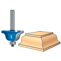
  2. Greetings everyone. I am using AutoCAD 2010 3D and though I am reasonably comfortable with 2D, the 3D stuff is hurting this wee brain of mine. Here is my objective. I have drawn a 3D image of a piece of wood in the 3D model space. I want to profile the edges of the wood with a router design, in this case a Roman Ogee, (see drawing). I have drawn the Roman Ogee in 2D, copied and pasted it into 3D then extruded it. I moved the Roman Ogee router profile into the area at the edge of the board I want the profile to be but I just can't figure out how to get the router profile to run along all 4 edges of the board to look like the image above. Can anyone help with a step by step procedure? Thanks
×
×
  • Create New...