All Activity
- Past hour
-
@Steven P I used it mostly for inserting text in blocks that need to be specific fonts, spacing, layers , and color. a side note even tho the blocks are exploded they are in the block library until you purge. keep that in mind when using generic block names. pasting a block from a different drawing will pull from the block library instead if they have the same name not the clipboard. So if block1 is a circle in DrawingA and a square in DrawingB. Selecting the block in drawingA and copy paste into DrawingB when it paste all the blocks will be squares. not the circles you copied.
- Today
-
Good stuff @mhupp! OP, why not just draw the polylines with LISP?
-
I didn't know that
-

Break an object at 2 points and replace the properties of the line
Nikon replied to Nikon's topic in AutoLISP, Visual LISP & DCL
We invent a "bicycle", but it turns out that it already exists in an ideal version. ObjectBreakV1-0.lsp Thanks, Lee Mac! -
little background on how DWG drawings work or how I understand. When you create or modify anything in a drawing it puts it at the end of drawing list. that is why you can select the last thing with (entlast) The blocks you are inserting is a made up of entity's and when you explode the block its gone but it's entity's are left in the drawing. even if its only one item its now under a different entity name. Your join command is saying join block 1 2 3 4 but you exploded them. you have to build another selection set of those entity's to join. so you create a place holder in the Drawing list with LastEnt insert and explode your block. then with the while its basically saying anything after this point in the list add to selection set SS. then pass the SS to the join command. (setq SS (ssadd)) (setq LastEnt (entlast)) (command "-insert" "*Infil_HL" '(0.0 0.0 0.0) "" "" "") (command "-insert" "*blk2" '(0.0 0.0 0.0) "" "" "") ;ent2 (command "-insert" "*blk3 '(0.0 0.0 0.0) "" "" "") ;ent3 (command "-insert" "*blk4" '(0.0 0.0 0.0) "" "" "") ;ent4 (while (setq LastEnt (entnext LastEnt)) (ssadd LastEnt SS) ) (command "_join" SS) -edit adding * infront of the block name AutoCAD inserts and immediately explodes it in one step.
-
Infil Panels-Layout1.pdfInfil Panels-Layout1.pdfInfil Panels-Layout1.pdfInfil Panels-Layout1.pdfInfil Panels-Layout1.pdfInfil Panels-Layout1.pdfHi All. I'm after some help with this pleasae. I want to insert 4 blocks into my drawing to form a square shape. The original 4 entities that I made are polylines and are saved as blocks in one drawing called BLOCKS_1. I start a new drawing and insert BLOCKS_1 into my drawing. This then makes the 4 polyline blocks available in my current drawing. I am then inserting the 4 blocks each at their relative 0,0,0 point which arranges the blocks how I want them. Heres where I cant get the join command to work. (I can manually join the 4 entities together using the JOIN command) After inserting the 4 blocks I am exploding them so they are now polylines and their end points are touching to form a square. this is an example of the code to only insert and explode 1 of the entities. I repeat this insert 3 more times, and change the ENTLAST to Ent2 Ent3 Ent4 (command "-insert" "Infil_HL" (0.0 0.0 0.0) "" "" "") ;Infil_HL is the block name one of the 4 entities thast are present in the drawing (setq Ent1 (entlast)) (command "_explode" Ent1) now when I run the join command it won't join the 4 entities into one. (command "_join" Ent1 Ent2 Ent3 Ent4) Regards Tony
- Yesterday
-

Function to calculate Mtext Justification based on Rotation
BIGAL replied to CivilTechSource's topic in AutoLISP, Visual LISP & DCL
No worries, you made a comment about the difficulty of making the desired pline, that is what I was what I was suggesting. -

Break an object at 2 points and replace the properties of the line
mhupp replied to Nikon's topic in AutoLISP, Visual LISP & DCL
cough -

AutoLISP: Change Block Spacing in X-Direction (Row-Wise, No Y-Shift)
BlackBox replied to Tamim's topic in AutoLISP, Visual LISP & DCL
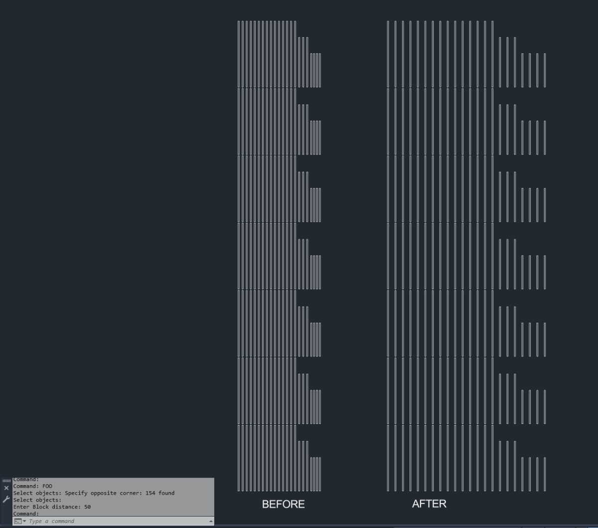
(vl-load-com) (defun c:FOO (/ *error* acDoc ss pt y item data blocks) (defun *error* (msg) (if ss (vla-delete ss)) (if acDoc (vla-endundomark acDoc)) (cond ((not msg)) ; Normal exit ((member msg '("Function cancelled" "quit / exit abort"))) ; <esc> or (quit) ((princ (strcat "\n** Error: " msg " ** "))) ; Fatal error, display it ) (princ) ) (if (and (ssget "_:L" '((0 . "INSERT"))) (setq d (getreal "\nEnter Block distance: ")) ) (progn (vla-startundomark (setq acDoc (vla-get-activedocument (vlax-get-acad-object))) ) (vlax-for x (setq ss (vla-get-activeselectionset acDoc)) (setq pt (vlax-get x 'insertionpoint)) (if (setq item (assoc (setq y (cadr pt)) data)) (setq data (subst (cons (car item) (append (cdr item) (list x))) item data) ) (setq data (cons (cons y (list x)) data)) ) ) (if data (foreach item data (setq blocks (vl-sort (cdr item) (function (lambda (a b) (< (car (vlax-get a 'insertionpoint)) (car (vlax-get b 'insertionpoint)) ) ) ) ) ) (setq pt (vlax-get (car blocks) 'insertionpoint)) (foreach block (cdr blocks) (vla-move block (vlax-3d-point (vlax-get block 'insertionpoint)) (vlax-3d-point (setq pt (polar pt 0.0 d))) ) ) ) ) ) ) (*error* nil) ) This works for each group of Blocks at a given Y level, based on the lowest X position in a given row as starting point.
-

AutoLISP: Change Block Spacing in X-Direction (Row-Wise, No Y-Shift)
Saxlle replied to Tamim's topic in AutoLISP, Visual LISP & DCL
Upload another example file to see what it looks like. But I'm afraid it can't be done easily, because you have to choose a reference point for the base block, and then rearrange the other blocks to be at equal distances. If you want to select "n" blocks, what can be a reference point from that selection set, which block? Also, they have different insertation points. -
Now it works perfectly
-

Help with Penn Foster structural drafting plate 1
ReMark replied to JimJames1978's topic in Student Project Questions
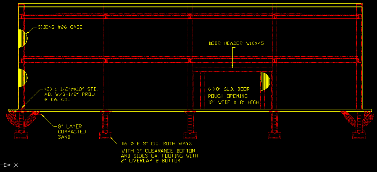
This is an example of what Plate 2 of the Penn-Foster structural project would look like.
-

AutoLISP: Change Block Spacing in X-Direction (Row-Wise, No Y-Shift)
Tamim replied to Tamim's topic in AutoLISP, Visual LISP & DCL
understood, but i have more than 10000 numbers for each CAD file -

Function to calculate Mtext Justification based on Rotation
CivilTechSource replied to CivilTechSource's topic in AutoLISP, Visual LISP & DCL
@BIGAL apologies if my query was not clear. I am trying basically to create the mtext around a house and I want the text justification to be relative to the points the user clicks. I think I will be approaching it using the three point system. e.g. if P1 & P2 angle is between between 270 to 90 then justification will be left and then check where p3 X,Y is relative to p1 X,Y to establish if top or bottom. Therefore it will be Top Left. -
AutoLISP: Change Block Spacing in X-Direction (Row-Wise, No Y-Shift)
Saxlle replied to Tamim's topic in AutoLISP, Visual LISP & DCL
Do it row by row, not selecting everything. -
AutoLISP: Change Block Spacing in X-Direction (Row-Wise, No Y-Shift)
Tamim replied to Tamim's topic in AutoLISP, Visual LISP & DCL
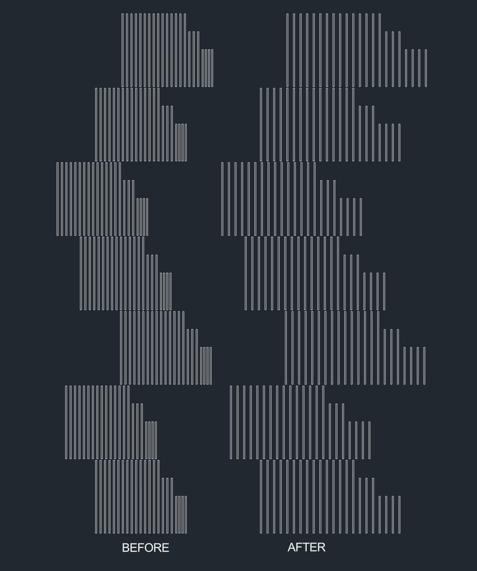
Thanks for the prog. However, this only works for a single X row. I need to select both top and bottom rows (like Y1 and Y2), and show the result below the image.
-
AutoLISP: Change Block Spacing in X-Direction (Row-Wise, No Y-Shift)
Saxlle replied to Tamim's topic in AutoLISP, Visual LISP & DCL
Hi @Tamim, Try with this: (prompt "\nTo run a LISP type: reara") (princ) (defun c:reara ( / old_osmode base_blk spacing ss base_blk_pt dist_blk_lst len i ins_pt dist n dist_n x_cord y_cord new_pt) (setq old_osmode (getvar 'osmode)) (setvar 'osmode 0) (setq base_blk (car (entsel "\nPick the base block:\n")) spacing (getreal "\nEnter the spacing:\n") ) (prompt "\nSelect BLOCK's:") (setq ss (ssget (list (cons 0 "INSERT"))) base_blk_pt (cdr (assoc 10 (entget base_blk))) dist_blk_lst (list) ) (if (ssmemb base_blk ss) (ssdel base_blk ss) ) (setq len (sslength ss) i 0 ) (while (< i len) (setq ins_pt (cdr (assoc 10 (entget (ssname ss i)))) dist (distance base_blk_pt ins_pt) dist_blk_lst (cons (list dist (ssname ss i)) dist_blk_lst) i (1+ i) ) ) (setq dist_blk_lst (vl-sort dist_blk_lst (function (lambda (x1 x2) (< (car x1) (car x2))))) n 0 ) (repeat (length dist_blk_lst) (setq dist_n (- (car (nth n dist_blk_lst)) spacing (* spacing n)) x_cord (- (cadr (assoc 10 (entget (cadr (nth n dist_blk_lst))))) dist_n) y_cord (caddr (assoc 10 (entget (cadr (nth n dist_blk_lst))))) new_pt (list x_cord y_cord) ) (command-s "_move" (cadr (nth n dist_blk_lst)) "" (cdr (assoc 10 (entget (cadr (nth n dist_blk_lst))))) new_pt) (setq n (1+ n)) ) (setvar 'osmode old_osmode) (prompt (strcat "\nThe " (itoa (length dist_blk_lst)) " are rearanged!")) (princ) ) See the following video how it works. Rearange blocks.mp4 Best regards. -
Break an object at 2 points and replace the properties of the line
Nikon replied to Nikon's topic in AutoLISP, Visual LISP & DCL
Unfortunately, the error remains ; error: too few arguments -
Break an object at 2 points and replace the properties of the line
BIGAL replied to Nikon's topic in AutoLISP, Visual LISP & DCL
Sorry my fault it has a typo I fixed code above There should be a space after the "/" was missing in code posted, I sort the variable names and put in code missed the needed space. (defun c:brkobj ( / cenpt end1 end2 ent ent1 ent2 obj1 obj2 pt1 pt2 rad st1 st2 type ) It has a linetype, and Linetype Scale so change both of those to suit. -
Break an object at 2 points and replace the properties of the line
Nikon replied to Nikon's topic in AutoLISP, Visual LISP & DCL
Thank You're absolutely right. Unfortunately, I was unable to verify the operation of the code. ; error: too few arguments -
Break an object at 2 points and replace the properties of the line
Nikon replied to Nikon's topic in AutoLISP, Visual LISP & DCL
Thank This code deletes the line between points pt1 and pt2. But I need to leave this line between the points pt1 and pt2 and change the properties of the line to a dashed line... -
Serious UI Failure in OpenDCL Studio - 'Options' and 'New Project' Menus are Missing
BIGAL replied to duke's topic in AutoLISP, Visual LISP & DCL
The developer reference refers to how to set the position of a dcl. in the current screen. Lee-mac has a great explanation of how to use it. I tried with a preset value of X&Y. https://www.lee-mac.com/dialogposition.html An example. I am running twin screens at 1920x1080 so the values below are screen on right with a Y value about 1/2 way up. (setq *screenpoint* '(2620 425)) (setq dcl_id (load_dialog fname)) (if (not (new_dialog "ddgetvalAH" dcl_id "" (cond ( *screenpoint* ) ( '(-1 -1) )))) (exit) ) To get a value, look at the X&Y of pos. (setq pos (done_dialog)) -
Break an object at 2 points and replace the properties of the line
Nikon replied to Nikon's topic in AutoLISP, Visual LISP & DCL
Thank The code works perfectly for straight sections. For circles and arcs, I would like to simply change the properties of the lines between points pt1 and pt2. There is no need to connect these points with a straight line. -
AutoLISP: Change Block Spacing in X-Direction (Row-Wise, No Y-Shift)
Tamim posted a topic in AutoLISP, Visual LISP & DCL
I need help with adjusting the X-direction spacing of multiple blocks (row-wise) in AutoCAD. The Y-position should remain unchanged. For example, the current spacing between blocks is 27 ft, but once I select all the blocks and input a new value like 23 or 24, the blocks should automatically update to the new spacing as per my requirement. BLK Sample.dwg -
Serious UI Failure in OpenDCL Studio - 'Options' and 'New Project' Menus are Missing
mhupp replied to duke's topic in AutoLISP, Visual LISP & DCL
You have to add a form to work on. DCLStudio.mp4