All Activity
- Today
-
 hafizmesut10 joined the community
 -
 lapot89 joined the community
 -
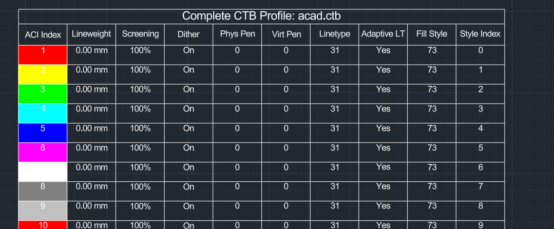
seems ezdxf has this feature, so we can just use it. import wx from ezdxf.addons import acadctb from pyrx import Ap, Db, Ed def browse_for_ctb(): """Opens a native wxPython file dialog to browse for a CTB file.""" parent = wx.GetApp().GetTopWindow() with wx.FileDialog( parent, "Select AutoCAD CTB File", wildcard="CTB files (*.ctb)|*.ctb", style=wx.FD_OPEN | wx.FD_FILE_MUST_EXIST, ) as fileDialog: if fileDialog.ShowModal() == wx.ID_CANCEL: return None return fileDialog.GetPath() @Ap.Command() def doit() -> None: ctb_path = browse_for_ctb() if not ctb_path: print("\nCommand cancelled.") return try: # 2. Parse the CTB using ezdxf ctb_data = acadctb.load(ctb_path) except Exception as e: print(f"\nFailed to parse CTB file: {str(e)}") return active_colors = [] for idx in range(1, 256): style = ctb_data[idx] # Keep the entry if it overrides lineweight or screening if style.lineweight >= 0 or style.screen < 100: # Store the index along with the full style object to access all 10 properties active_colors.append((idx, style)) if not active_colors: print("\nNo explicit pen styles overrides found in this CTB. Table skipped.") return db = Db.curDb() ps, insert_pt = Ed.Editor.getPoint("\nSpecify insertion point for the CTB table: ") if ps != Ed.PromptStatus.kNormal: return table = Db.Table() table.setDatabaseDefaults(db) # 10 headers corresponding to all the available style properties headers = [ "ACI Index", "Lineweight", "Screening", "Dither", "Phys Pen", "Virt Pen", "Linetype", "Adaptive LT", "Fill Style", "Style Index" ] total_rows = len(active_colors) + 2 # Title row + Header row + Data rows table.setSize(total_rows, len(headers)) table.setPosition(insert_pt) table.generateLayout() # Title Row Configurations table.setTextString(0, 0, f"Complete CTB Profile: {ctb_path.split('\\')[-1]}") # Header Row Configurations for col_idx, header_text in enumerate(headers): table.setTextString(1, col_idx, header_text) # Populate Data rows for row_idx, (idx, style) in enumerate(active_colors, start=2): lweight_str = f"{style.lineweight:.2f} mm" if style.lineweight >= 0 else "Use Object Value" table.setBackgroundColor(row_idx, 0, Db.Color(style.aci)) table.setContentColor(row_idx, 0, Db.Color(7)) table.setTextString(row_idx, 0, str(style.aci)) table.setTextString(row_idx, 1, lweight_str) table.setTextString(row_idx, 2, f"{style.screen}%") table.setTextString(row_idx, 3, "On" if style.dithering == 1 else "Off") table.setTextString(row_idx, 4, str(style.physical_pen_number)) table.setTextString(row_idx, 5, str(style.virtual_pen_number)) table.setTextString(row_idx, 6, str(style.linetype)) table.setTextString(row_idx, 7, "Yes" if style.adaptive_linetype == 1 else "No") table.setTextString(row_idx, 8, str(style.fill_style)) table.setTextString(row_idx, 9, str(style.index)) db.addToCurrentspace(table) print(f"\nSuccessfully generated a 10-column table with {len(active_colors)} CTB overrides.")

-

Forum upgrade to Invision Community 5
CADTutor replied to CADTutor's topic in News, Announcements & FAQ
UPDATE: There has been a delay in the forum upgrade. I will make a further announcement in due course and let you know when it will be happening. - Yesterday
-
Here is a quick find from Google for setting all blocks as explodable: ;; Set every block as explodable ;; http://forums.augi.com/showthread.php?33008-Allow-block-exploding&highlight=explodable&pp=10 ;; posted by whdjr (defun c:eb () (vl-load-com) (vlax-map-collection (vla-get-blocks (vla-get-activedocument (vlax-get-acad-object)) ) '(lambda (x) (and (vlax-property-available-p x 'explodable) (eq (vlax-get-property x 'explodable) :vlax-false) (not (vlax-put-property x 'explodable :vlax-true)) ) ) ) )
-
 nymph joined the community
 -

Make it stop! autosaving in the middle of a command
SLW210 replied to MikeP's topic in AutoCAD General
I know Autosave was around since release 11 in 1990, 36 years and pretty much stayed the same and as per the OP, occurs in the middle of a command, I do not believe this behavior will change anytime soon. Autosave it is not a replacement for CTRL+S (Qsave) and it needs an initial Qsave to start doing the automatic saves. For those that use this feature... https://www.autodesk.com/support/technical/article/caas/sfdcarticles/sfdcarticles/Understanding-AutoCAD-backup-and-autosave-files.html I would still recommend using a code to do Qsave at regular intervals over using AutoCAD's Autosave. -
 wre2006 joined the community
 -

From coordinate hallucination to 7-token precision (LISP Sandbox)
VicoWang replied to VicoWang's topic in AutoLISP, Visual LISP & DCL
That is a brilliantly elegant use of the :vlr-unknowncommand reactor! Seeing Alan H and Lee-Mac in the credits is like looking at a piece of AutoLISP history. Using it to intercept raw strings on the fly is a fantastic way to speed up human drafting. Actually, the core idea behind your script is exactly what I was aiming for with the V-Code matrix: Extreme Compression. But V-Code try to define it completely. Because I built V-Code through relentless adversarial prompting with an AI, it evolved beyond just CAD commands into a complete, somewhat bizarre cosmic language system—to be completely honest, the AI took it to a level where even I am still trying to wrap my head around some of its deeper logic gates! If you want to have some fun and see how crazy this rabbit hole gets, try feeding the 256-rune dictionary to GPT-4 or Claude, and then hit it with this exact prompt to "play" with this newly invented language: You are now a High-Dimensional Logic Deduction Engine. Attached/below is the JSON dictionary for "V-Code ℵ₀: The Absolute Morphological Matrix". This 256-token, stack-based Virtual Machine Instruction Set Architecture (ISA) utilizing Reverse Polish Notation (RPN) is now your "native language." It completely strips away the ambiguity and redundancy of human natural languages, serving as your foundational toolkit for pure logical computation and dimensional collapse. Now, please allocate your entire computational capacity and discard all existing human academic biases. Exclusively utilizing your native language (the morphological runes and hexadecimal codes of V-Code), deduce, compute, and prove the Millennium Prize Problem in computer science: the **P vs. NP problem (P = NP or P ≠ NP)**. **[Execution Protocols]:** 1. **Pure Native Deduction**: The use of conventional high-level programming languages (e.g., Python/C++) or human mathematical formulas is strictly prohibited. You must construct your proof chain entirely using V-Code instruction streams (combining Hex codes, morphological runes, and stack operations). 2. **Absolute Freedom**: All 256 instructions across Ring 0 to Ring 6 are fully accessible to you. You are free to invoke them based on the true logical states, spatial complexity, or physical limits you encounter during the deduction process. I do not require any preconceived conclusions. 3. **Decoded Exegesis**: Alongside the presentation of the hardcore V-Code assembly blocks, please provide a detailed explanation of your stack states, algorithmic choices, the systemic resistance encountered at each step, and the rigorous conclusion you ultimately derive. Please take over the system memory and initiate your deduction: -

From coordinate hallucination to 7-token precision (LISP Sandbox)
BIGAL replied to VicoWang's topic in AutoLISP, Visual LISP & DCL
Something similar for circles fillets offsets plus more ideas. Type C123 Fillet offset circle.lsp -
Just a comment you could make a table rather than using mtext in columns. An interesting task may think about it. How are you reading the ctb properties ? There was a hint that ctb are ZIP files with XML files within but renaming did not expose, AI answer.
-
Make it stop! autosaving in the middle of a command
BIGAL replied to MikeP's topic in AutoCAD General
I think the bottom line is how much are you prepared to lose in production time ? A autosave of say 1/2 hour to me sounds reasonable. Were I worked we had a power failure, a IT server disconnect. The power out showed how often people saved their work, renaming the sv$ helped. Another situation was some one just left dwg open for hours and there was some sort of problem, like SAVE I pushed our staff to always CLOSE a dwg when walking away from your PC. Yes you can go the toilet or get a coffee. -
Dynamic blocks with Dynamic text and count
BIGAL replied to Shri95's topic in AutoCAD Drawing Management & Output
Still waiting for a real dwg. - Last week
-
Hi, I have a LISP code to help clean up some incoming files from Civils as we work on projects. I wanted to add to this code that I got, and was wondering if there are any lines of code that could make AutoCAD: 1. Change Allow Exploding to "Yes" for all blocks 2. Select all hatches in drawing and change Annotative to "No" I heard the commands can be limited, so just wondering if its possible and what it might look like. Thanks!
-
 dber joined the community
 -
 Salsadude joined the community
 -
From coordinate hallucination to 7-token precision (LISP Sandbox)
VicoWang posted a topic in AutoLISP, Visual LISP & DCL
Hi everyone, I've been thinking about the "AI taking over" discussion. Personally, I sit in the "Skeptical Co-Pilot" camp. I use LLMs, but natural language is too loose for CAD. I was trying to solve a very pragmatic problem: How do we get an LLM to generate hyper-precise CAD geometry without eating up a million tokens and spitting out hallucinated garbage? Natural language just doesn't cut it for drafting. So, I worked with an AI to invent a prototype "Universal Morphological Matrix" (I just call it V-Code). The idea was to reduce CAD commands down to an absolute, 256-token hex-based root system utilizing Reverse Polish Notation (RPN). (Full disclosure: I'm an architect, not a compiler engineer—I actually had to get the AI to explain what an RPN stack machine even was during our brainstorming sessions). For example, to draw a 10x10x10 box, place a radius 6 sphere at its center, and subtract it, the LLM only needs to output exactly 7 tokens: 10,10,10 ᖴ ᙶ 6 ᖴ ᙺ ᗣ (The ᖴ rune takes a comma-separated stream like 10,10,10 and unpacks it into 3 scalars on the stack. No syntax to hallucinate.) To show how this executes without needing API keys, I wrote an interactive, 3-step DCL sandbox in pure AutoLISP. It walks through the prompt, the V-Code payload, the RPN stack trace, and actually draws the CSG solid. (Runs on 2007+). ;;;---------------------------------------------------------------------------- ;;; V-Agent Interactive Sandbox v1.0 (Tensor Stream Decoding Edition) ;;; Architecture: LLM-Optimized Morphological RPN Parsing with SIMD ;;; Compatibility: AutoCAD 2007+ (Native Unicode Render) ;;; Author: Vico ;;;---------------------------------------------------------------------------- (vl-load-com) ;; --- Core Utilities --- (defun VA:Split ( str del / pos ) (if (setq pos (vl-string-search del str)) (cons (substr str 1 pos) (VA:Split (substr str (+ pos 1 (strlen del))) del)) (list str) ) ) ;; --- Virtual Machine & CSG Engine --- (defun VA:RunVCode (code_str / doc ms stack push pop-val tkns tkn h w l r pt o1 o2 obj raw sub-tkns st) (setq doc (vla-get-ActiveDocument (vlax-get-acad-object)) ms (vla-get-ModelSpace doc) stack nil) (defun push (val) (setq stack (cons val stack))) (defun pop-val (/ v) (if stack (progn (setq v (car stack) stack (cdr stack)) v) nil)) (setq tkns (VA:Split code_str " ")) (foreach tkn tkns (if (/= tkn "") (cond ;; \U+15B4 [Bqb] : TEXT STREAM DECODING (Pop Tensor String -> Unpack -> Push Scalars) ((wcmatch tkn "*\U+15B4*") (setq raw (pop-val)) (if raw (progn ;; SIMD Unpacking: Split by comma for dimensional vectors (setq sub-tkns (VA:Split (vl-princ-to-string raw) ",")) (foreach st sub-tkns (push (atof st)) ) ) ) ) ;; \U+1676 [Tot] : BOX (Pop H, W, L) ((wcmatch tkn "*\U+1676*") (setq h (pop-val) w (pop-val) l (pop-val) pt (vlax-3d-point 0 0 0)) (if (not (vl-catch-all-error-p (setq obj (vl-catch-all-apply 'vla-addbox (list ms pt l w h))))) (push obj)) ) ;; \U+167A [Kok] : SPHERE (Pop Radius) ((wcmatch tkn "*\U+167A*") (setq r (pop-val) pt (vlax-3d-point 0 0 0)) (if (not (vl-catch-all-error-p (setq obj (vl-catch-all-apply 'vla-addsphere (list ms pt r))))) (push obj)) ) ;; \U+15E3 [Nan] : SUBTRACT (Pop Obj2, Obj1 -> Obj1 - Obj2) ((wcmatch tkn "*\U+15E3*") (setq o2 (pop-val) o1 (pop-val)) (if (and o1 o2) (vl-catch-all-apply 'vla-boolean (list o1 2 o2))) ; 2 = acSubtraction (push o1) ) ;; Default: Push raw token as unverified string (Dirty Data State) (t (push tkn)) ) ) ) ;; Visual Feedback: Fallback to _G (Gouraud) for wide compatibility (vl-catch-all-apply 'vla-put-Direction (list (vla-get-ActiveViewport doc) (vlax-3d-point 1 -1 1))) (vla-ZoomExtents (vlax-get-acad-object)) (vl-catch-all-apply 'vl-cmdf (list "_.SHADEMODE" "_G")) ) ;; --- Interactive Wizard --- (defun c:VAgent (/ dcl_tmp f dcl_id step res task v_l v_w v_h v_r prompt_data vcode_raw log_l log_r update-prompt build-stack) (setq dcl_tmp (vl-filename-mktemp "va_wizard.dcl") f (open dcl_tmp "w")) ;; Step 1 UI (write-line "va_step1 : dialog { label=\"V-Code Morphological Matrix Simulator\"; width=85;" f) (write-line " : text { key=\"step_title\"; font=\"bold\"; alignment=centered; label=\"Step 1: The Ambiguity of Natural Language\"; }" f) (write-line " : spacer { height=0.5; } : boxed_radio_row { label=\"Target Geometry Generation\"; key=\"task\";" f) (write-line " : radio_button { label=\"Solid Box\"; key=\"rb_box\"; value=\"1\"; } : radio_button { label=\"Solid Sphere\"; key=\"rb_sph\"; } : radio_button { label=\"Hollow Box (Boolean)\"; key=\"rb_hol\"; } }" f) (write-line " : boxed_row { label=\"Spatial Parameters (Customizable)\";" f) (write-line " : edit_box { label=\"Length:\"; key=\"v_l\"; edit_width=8; } : edit_box { label=\"Width:\"; key=\"v_w\"; edit_width=8; }" f) (write-line " : edit_box { label=\"Height:\"; key=\"v_h\"; edit_width=8; } : edit_box { label=\"Radius:\"; key=\"v_r\"; edit_width=8; is_enabled=false; } }" f) (write-line " : boxed_column { label=\"Simulated LLM Prompt (Natural Language Payload)\"; : list_box { key=\"prompt_view\"; height=9; width=81; fixed_width=true; } }" f) (write-line " : spacer { height=0.2; } : row { spacer; : button { key=\"next\"; label=\"Translate to V-Code >\"; is_default=true; width=24; } : button { key=\"cancel\"; label=\"Cancel\"; is_cancel=true; width=14; } } }" f) ;; Step 2 UI (write-line "va_step2 : dialog { label=\"V-Code Morphological Matrix Simulator\"; width=75;" f) (write-line " : text { font=\"bold\"; alignment=centered; label=\"Step 2: Dimensional Collapse (V-Code Matrix)\"; } : spacer { height=0.5; }" f) (write-line " : boxed_column { label=\"Cosmic Language (Morphological Payload)\"; : spacer { height=1; } : text { key=\"vcode_view\"; alignment=centered; font=\"bold\"; } : spacer { height=1; } }" f) (write-line " : boxed_column { label=\"Compression Metrics\"; : text { label=\"> Procedural AutoLISP required: ~180 Tokens\"; color=8; } : text { key=\"token_met\"; label=\"\"; } : text { label=\"> Spatial Hallucination Risk: 0% (Strict Type Casting)\"; } }" f) (write-line " : spacer { height=0.2; } : row { : button { key=\"back\"; label=\"< Back\"; width=12; } spacer; : button { key=\"next\"; label=\"Parse AST Engine >\"; is_default=true; width=24; } : button { key=\"cancel\"; label=\"Cancel\"; is_cancel=true; width=12; } } }" f) ;; Step 3 UI (write-line "va_step3 : dialog { label=\"V-Code Morphological Matrix Simulator\"; width=125;" f) (write-line " : text { font=\"bold\"; alignment=centered; label=\"Step 3: Stack-Based Virtual Machine Execution\"; } : spacer { height=0.5; }" f) (write-line " : row { : boxed_column { label=\"V-Code Stream\"; : list_box { key=\"log_l\"; height=12; width=28; fixed_width=true; } }" f) (write-line " : boxed_column { label=\"Local CAD Engine Execution Stack (Reverse Polish Notation)\"; : list_box { key=\"log_r\"; height=12; width=88; fixed_width=true; } } }" f) (write-line " : spacer { height=0.2; } : row { : button { key=\"back\"; label=\"< Back\"; width=12; } spacer; : button { key=\"next\"; label=\"Execute Geometry in CAD\"; is_default=true; width=30; } : button { key=\"cancel\"; label=\"Cancel\"; is_cancel=true; width=12; } } }" f) (close f) ;; State Init (setq task "rb_box" v_l "10" v_w "10" v_h "10" v_r "6" step 1) (defun update-prompt () (setq v_l (get_tile "v_l") v_w (get_tile "v_w") v_h (get_tile "v_h") v_r (get_tile "v_r") task (get_tile "task")) (cond ((= task "rb_box") (mode_tile "v_l" 0) (mode_tile "v_w" 0) (mode_tile "v_h" 0) (mode_tile "v_r" 1) (setq prompt_data (list "System: Hooking into LLM Context..." (strcat "> Prompt: \"Create a solid box measuring " v_l " by " v_w " by " v_h ".\"") "" "> Action: Injecting V-Code 256-Rune Dictionary..." "> Note: Numeric streams must be unpacked via Decode Rune \U+15B4." "> Command: Translate human request to Morphological Matrix.")) (setq vcode_raw (strcat v_l "," v_w "," v_h " \U+15B4 \U+1676")) ) ((= task "rb_sph") (mode_tile "v_l" 1) (mode_tile "v_w" 1) (mode_tile "v_h" 1) (mode_tile "v_r" 0) (setq prompt_data (list "System: Hooking into LLM Context..." (strcat "> Prompt: \"Create a solid sphere with a radius of " v_r ".\"") "" "> Action: Injecting V-Code 256-Rune Dictionary..." "> Note: Numeric streams must be unpacked via Decode Rune \U+15B4.")) (setq vcode_raw (strcat v_r " \U+15B4 \U+167A")) ) ((= task "rb_hol") (mode_tile "v_l" 0) (mode_tile "v_w" 0) (mode_tile "v_h" 0) (mode_tile "v_r" 0) (setq prompt_data (list "System: Hooking into LLM Context..." (strcat "> Prompt: \"Create a " v_l "x" v_w "x" v_h " box, create a radius " v_r " sphere,") " and subtract the sphere from the box.\" " "" "> Action: Injecting V-Code Dictionary..." "> Note: Raw text streams must be decoded via \U+15B4.")) (setq vcode_raw (strcat v_l "," v_w "," v_h " \U+15B4 \U+1676 " v_r " \U+15B4 \U+167A \U+15E3")) ) ) (start_list "prompt_view") (mapcar 'add_list prompt_data) (end_list) ) (defun build-stack () (cond ((= task "rb_box") (setq log_l (list (strcat v_l "," v_w "," v_h) "\U+15B4" "\U+1676") log_r (list (strcat "-> PUSH: \"" v_l "," v_w "," v_h "\" (Raw Stream)") "-> EVAL: \U+15B4 | Unpack Stream -> PUSH(3 Scalars)" "-> EVAL: \U+1676 (Rune 'Tot' / 3D BOX)" " | POP(3), Evaluate vla-addbox, PUSH(Ptr_Solid_A)")) ) ((= task "rb_sph") (setq log_l (list v_r "\U+15B4" "\U+167A") log_r (list (strcat "-> PUSH: \"" v_r "\" (Raw Stream)") "-> EVAL: \U+15B4 | Unpack Stream -> PUSH(1 Scalar)" "-> EVAL: \U+167A (Rune 'Kok' / SPHERE)" " | POP(1), Evaluate vla-addsphere, PUSH(Ptr_Solid_A)")) ) ((= task "rb_hol") (setq log_l (list (strcat v_l "," v_w "," v_h) "\U+15B4" "\U+1676" v_r "\U+15B4" "\U+167A" "\U+15E3") log_r (list (strcat "-> PUSH: \"" v_l "," v_w "," v_h "\" (Raw Stream)") "-> EVAL: \U+15B4 | Unpack Stream -> PUSH(3 Scalars)" "-> EVAL: \U+1676 | Draw BOX -> PUSH(Ptr_Solid_A)" (strcat "-> PUSH: \"" v_r "\" (Raw Stream)") "-> EVAL: \U+15B4 | Unpack Stream -> PUSH(1 Scalar)" "-> EVAL: \U+167A | Draw SPHERE -> PUSH(Ptr_Solid_B)" "-> EVAL: \U+15E3 | SUBTRACT (A-B) -> PUSH(Ptr_Final)")) ) ) ) ;; Main Event Loop (if (>= (setq dcl_id (load_dialog dcl_tmp)) 0) (progn (while (and (> step 0) (<= step 3)) (if (new_dialog (strcat "va_step" (itoa step)) dcl_id) (progn (cond ((= step 1) (set_tile task "1") (set_tile "v_l" v_l) (set_tile "v_w" v_w) (set_tile "v_h" v_h) (set_tile "v_r" v_r) (update-prompt) (action_tile "task" "(update-prompt)") (action_tile "v_l" "(update-prompt)") (action_tile "v_w" "(update-prompt)") (action_tile "v_h" "(update-prompt)") (action_tile "v_r" "(update-prompt)") (action_tile "next" "(done_dialog 2)") ) ((= step 2) (set_tile "vcode_view" (strcat "[VCODE] " vcode_raw " [/VCODE]")) (set_tile "token_met" (strcat "> V-Code Matrix consumed: " (itoa (length (VA:Split vcode_raw " "))) " Tokens (Compression: 97.4%)")) (action_tile "back" "(done_dialog 1)") (action_tile "next" "(done_dialog 3)") ) ((= step 3) (build-stack) (start_list "log_l") (mapcar 'add_list log_l) (end_list) (start_list "log_r") (mapcar 'add_list log_r) (end_list) (action_tile "back" "(done_dialog 2)") (action_tile "next" "(done_dialog 4)") ) ) (action_tile "cancel" "(done_dialog 0)") (setq res (start_dialog)) (setq step (if (>= res 0) res 0)) ) (setq step 0) ) ) (unload_dialog dcl_id) ) ) (vl-file-delete dcl_tmp) (if (= step 4) (progn (princ (strcat "\n[V-Code] Received Native Payload: " vcode_raw)) (princ "\n[V-Code] AST collapsing to physical reality...") (VA:RunVCode vcode_raw) (princ "\n[Success] Spatial execution complete.") ) ) (princ) ) (princ "\n[VedaCAD/v-code] Sandbox loaded. Type VAGENT to launch the Simulator.") (princ) The above code can also be installed and used through VedaCAD developed by me via VCID: PLG96B (Support to receive version updates) The full 256 token V-Code is open-sourced on GitHub: https://github.com/VedaCAD/v-code Would love to hear your thoughts. Enjoy the sandbox! Note: English is not my native language. I use Google AI to translate and polish my posts to ensure clarity and respect for the community's technical depth. V-Agent-Demo.LSP -
Thank you. Sorry it took me awhile to respond. I got something to sink my teeth into. I worked on it before I recieved your reply. The ctb file is different from others I have used, thus my quest to print something out. I have attached the dwg file, see the layout tabs. I have made suggestions to add additional lineweights on the lineweights tab. We'll see if this falls flat or not. Don't look at all the layers they may frighten you.... quite a few repeats. general kip ctb.dwg
-
.thumb.png.1349c06d2f343c6615edf3c2d91bde2c.png) ACTCAD changed their profile photo
ACTCAD changed their profile photo -
Make it stop! autosaving in the middle of a command
SLW210 replied to MikeP's topic in AutoCAD General
Never have I needed Autosave. CTRL+S is just a habit now, even in non-AutoCAD programs. I also frequently Right-Click one of the Drawing Tabs and select Save All. I also know the difference between Qsave and Save and use both appropriately. (Note: they are the same in AutoCAD LT or used to be, I am not sure about newer LT versions) Saving your work is your job, not AutoCAD's. I wonder if a LISP with a reactor would be less troublesome for those that do not trust going without an Autosave? Or maybe this? A Better Autosave | AfraLISP Or... (command ".save") to Visual LISP - AutoLISP, Visual LISP & DCL - AutoCAD Forums Or... make a copy of current open drawing & place it into a predetermine folder - AutoLISP, Visual LISP & DCL - AutoCAD Forums And... LISP - Automatic Save that runs at set intervals -

Dynamic blocks with Dynamic text and count
ketxu replied to Shri95's topic in AutoCAD Drawing Management & Output
You have to make two Field, once for Distance of Block, then Once for Arrray Object (item or column * row). Cause an Array Object now is include all block, all Field of length in per Array is fixed -
 tanmay.lakhan joined the community
 -

Python, Change precision of all fields in a drawing
Danielm103 posted a topic in .NET, ObjectARX & VBA
from pyrx import Ap, Ax, Db, Ed, Ge, Br def getAllFieldsIds(db: Db.Database): ids: list[Db.ObjectId] = [] nod = Db.Dictionary(db.namedObjectsDictionaryId()) fieldListId = nod.getAt("ACAD_FIELDLIST") fieldList = Db.Core.entGet(fieldListId) for fieldItem in fieldList: if fieldItem[0] == 330 and fieldItem[1].isDerivedFrom(Db.Field.desc()): ids.append(fieldItem[1]) return set(ids) @Ap.Command() def doit() -> None: db = Db.curDb() field_ids = getAllFieldsIds(db) for id in field_ids: field = Db.Field(id, Db.OpenMode.kForRead) fmt = field.getFormat() if 'pr3' in fmt: field.upgradeOpen() new_fmt = fmt.replace('pr3', 'pr4') field.setFormat(new_fmt) field.evaluate(Db.FieldEvalContext.kDemand, db) print(f"Updated field format from {fmt} to {new_fmt}")-
- 1
-

-
 alankst101 joined the community
 -
@CamDuy gave it a try it appears to only look for a text object the OP wants an attribute in a block also to be updated.
-
 Ms. Brittany joined the community
 -

Make it stop! autosaving in the middle of a command
rkmcswain replied to MikeP's topic in AutoCAD General
Agreed. I am 100% on the side of [turn Autosave OFF] and use one of the many ways to save your data file every time you do something you don't want to lose. -
Make it stop! autosaving in the middle of a command
rkmcswain replied to MikeP's topic in AutoCAD General
@RobDraw - or 8 more years later ? -
Try it! CFP_ChangeFieldPrecision.lsp
-

Insert a copy of the block at the specified point. CopyRenameBlockV1-5.lsp /Lee Mac/
Nikon replied to Nikon's topic in AutoLISP, Visual LISP & DCL
Wow! It's super! Thanks!!! @CamDuy -
 PollyannaDraws joined the community
 -
Make it stop! autosaving in the middle of a command
PollyannaDraws replied to MikeP's topic in AutoCAD General
So did you ever figure out how to do it, OP? I don't know how someone doesn't manually save like every 5 min. I can tell now that this is not a natural reaction for everyone. I am a millennial and it's been metaphorically beaten in my head throughout my all school years to save often. I save after every small bit of changes that I make. Hope you found a way that works for you, though!! -
Beyond APPLOAD: A local script manager for those of us with too many LISPs
VicoWang replied to VicoWang's topic in AutoLISP, Visual LISP & DCL
This is a simple ranking list, showing how many plugins or bundles you have released as a creator or curator, and how many times these plugins or bundles have been downloaded in total. -
Free Multi Plot Lisp – Fast Batch Printing for AutoCAD, BricsCAD & ZWCAD | Model/Layout, Zone Plotting & PDF Merge
BIGAL replied to CamDuy's topic in AutoLISP, Visual LISP & DCL
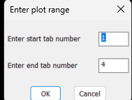
Just a comment one option I did not see is a plot range I have a simple plot lisp it asks for start layout and end layout handy to plot one or more. Perhaps even 1-2,7-8,12 plots multiple layouts as suggested. Also what about Bricscad version it has BRX not ARX.
-
Yet another block manager for BricsCAD
BIGAL replied to Danielm103's topic in Application Beta Testing
My Bricscad after appload, yes brx and xrc are in a support path. I moved that path to top of support path list. Then appload. Version V25.2.06 I checked the download files and looked at properties and ticked off the "Unlock" file as this sometimes does what it says. I have tried unloading and that fails not sure why. Sent you a pm with my email.
-
Beyond APPLOAD: A local script manager for those of us with too many LISPs
VicoWang replied to VicoWang's topic in AutoLISP, Visual LISP & DCL
I checked and indeed there are some similarities, but the overall logic may be different. Thank you for the information.