All Activity
- Past hour
-

5 CAD Commands That Can Save You More Time Than You Think
Paul Li replied to indiancad's topic in AutoCAD 2D Drafting, Object Properties & Interface
Then there's this by ChatGPT to replace Express Tools Burst with lisp version that converts Attributes to Text keeping the original Attributes. This can be run with Accoreconsole in a script: (BurstAttrBlock BlockNameWithAttributes) BurstAttrBlock.lsp BurstAttrBlock.scr - Today
-

5 CAD Commands That Can Save You More Time Than You Think
SLW210 replied to indiancad's topic in AutoCAD 2D Drafting, Object Properties & Interface
As programmable as AutoCAD can be, Excel (and LibreOffice Calc, et. al.) IMO handle Text, MText, Attributes, etc. much better. -
5 CAD Commands That Can Save You More Time Than You Think
SLW210 replied to indiancad's topic in AutoCAD 2D Drafting, Object Properties & Interface
I forgot about this. Att2Text.lsp converts attributes in a block to text outside the block, removes the attribute from the block and Att2TxtBlk.lsp converts attributes in a block to text outside the block, leaves the attribute in the block. Att2Text.lsp Att2TxtBlk.lsp -
I almost forgot, I ended up redoing the original turn off the center mark for diameter and radius dimensions to better maintain associativity. If there is still an issue with losing associativity for the dimensions you can run this separately. If there are still center marks, they are likely hard-coded overrides and I couldn't find any method to keep from breaking associativity in those instances. Maybe someone smarter or at least more familiar with such cases can explain a better method. F_Off_Mrks.lsp
-
Another route: since each luminaire type is already on its own layer, pick one exported block per type and make a proper block from it (or use your standard library block), keeping the same insertion point at the fixture centre. In current AutoCAD versions, BLOCKREPLACE lets you select all the unique blocks on that layer and replace them in one go with the chosen block. Select them first with QSELECT or SELECTSIMILAR, filtering by layer. On LT 2018 there is no BLOCKREPLACE, so use a free swapblock-style LISP only if your LT build supports it, or insert your block and copy it to each fixture position using the exported blocks as a guide. Check scale and rotation afterwards, because exported fixtures can differ in units. Keep all luminaires on a dedicated lighting layer.
-
DIALux exports each luminaire as its own uniquely named block, so the names can't be changed at export. Best fix is after export: put one luminaire of each type on its own layer (DIALux usually keeps types on separate layers), then create a single clean block for that type, with the insertion point at the fixture centre. Use the Express Tools BLOCKREPLACE (or SWAPBLOCK, or the native BLOCKREPLACE in AutoCAD 2023 and later) to swap all the exported blocks on that layer for your block. Select them with QSELECT or SELECTSIMILAR first. Check the scale and rotation after the swap, since DIALux blocks are often in metres or millimetres. Finally, purge the old blocks and keep all fixtures on a dedicated lighting layer.
-
 AONE_LED joined the community
-
Ever sent a drawing to a colleague, only to get a message back that the xrefs are missing? Or the font is wrong? AutoCAD eTransmit exists to prevent exactly that. It bundles a drawing together with everything it depends on, including xrefs, images, fonts, plot styles, and other referenced files, into a single package that’s ready to send. Most people use it with default settings and never look further, but there are some features in the dialog that a casual user may not be aware of. Today, I’m going to walk through them. How to open AutoCAD eTransmit and use Transmittal Setups First things first. You can find eTransmit in the Application Menu (the big red A in the corner), within the Publish fly-out menu. Or you can be like me and type in ET from the command line or dynamic input box. eTransmit will be your first option. The Create Transmittal dialog will appear. You’ll see the files tree, where all of the references and support files will be displayed. You’ll also select other drawings to transmit here. On the right, there will be a list of saved transmittal setups, with Standard being the default option. Below that is a very important button: the Transmittal Setups button. Clicking it displays a small dialog that allows you to create or remove setups, rename them, or, most importantly, Modify them. Choose the setup that you want, and click the Modify button. In all honesty, as a CAD Manager I would rarely create new setups, but would just modify Standard to my current needs. I would always check the settings first anyway, so I found no point in predefining them. As always, your mileage may vary. The Transmittal Setup options Finally, the Modify Transmittal Setup dialog will appear. This is where the rubber meets the road. There are four panels in the dialog: The type and location, path options, other actions, and what types of entities get included in the transmittal package. Let’s look at each. First up is the type and location. You can write the files to a folder (or folders), or have it create a Zip file for you. Your choice. Note that if you select to make a Zip file, the bottom file name option will become disabled. Your next choice is the file format. You can keep the files in their current DWG format, or save down to anything from 2000 on. I’ve had clients that require a certain format – it happens. This is also a convenient way to batch file format change. Below that is a checkbox for visual fidelity. Please click the info icon next to it for a detailed explanation, but typically, leave it checked, especially if you use annotative objects. If you don’t, it won’t matter anyway. Next, define where the files you’re creating will be saved. Only you know where this will be, but please choose wisely. Next is the path options section. This section is very important. When the transmittal reaches its destination (let’s say another company), how do they see it? How do the references resolve? You can create an organized folder structure that is the same as your project. It is also the default. You’ll simply need to specify the root folder of the project. This option is for references that utilize relative pathing. The recipient can place it in any folder structure that they want, and everything will resolve. The bottom two options are for those who do not use relative pathing. You can keep them “as is”, in which case the recipient will need to make sure they have a duplicate server drive setup as you do. Or, you can specify that the new files will all be written into a single folder. Why would you do that? Since they all have hard-coded reference paths, how will they resolve? Before considering the save path, AutoCAD always looks in the current folder for the reference, and if not found, only then does it try the saved path. This option lets you get away with the not-so-great option of hard-coded pathing. Moving on the upper right section, you have some checkbox options to choose from, a couple of which are what I consider just being a friendly transmitter. Unless you have a firm directive to do otherwise, please set the default plotter to “none” and purge the drawings as you go. That leaves us with Bind External References. Much like using the save format as a batch save-down tool, this option can be used as a batch binding tool. Selecting this option will allow you to bind as a “bind” or an “insert”. If you’re doing this, you should already know the difference. But here’s a hard-learned lesson for you. There are a LOT of things that will keep an Xref from binding, but this option does nothing to warn you about whether it succeeds or not. You’ll finish the transmittal and assume that everything bound correctly. Do not trust that it succeeded. Whenever I use this option, I always use the external Reference Manager to check the transmittal. Please take heed. Future you will thank me. Finally, it’s up to you to choose what gets included in the transmittal (or not). If you use some custom fonts, you may want to send them along so that the drawings appear as yours do. The middle three options are on by default, but even if your files don’t contain any of them, it won’t affect anything. The last option is for including unloaded references. I’m sure there are reasons to include these, but generally, if a reference is unloaded, there’s a good reason, and sending it along would only create unnecessary bloat in the transmittal. Again though… you do what you need. AutoCAD eTransmit and Sheet Set Manager I kind of glossed over the file selection button in the first dialog. Projects can get large. Manually selecting your files doesn’t need to be tedious, which is yet another reason to use AutoCAD’s Sheet Set Manager. The eTransmit command is right there for you. Hey, when it comes time to transmit your drawings or entire project to someone else, make sure they’re happy with what they get. You wouldn’t want to get drawings with references that don’t resolve, so why would they? Always transmit friendly files with eTransmit. More Tuesday Tips Check out our whole Tuesday Tips series for ideas on how to make AutoCAD work for you. The post AutoCAD eTransmit: Tuesday Tips With Frank appeared first on AutoCAD Blog. View the full article
-

5 CAD Commands That Can Save You More Time Than You Think
Steven P replied to indiancad's topic in AutoCAD 2D Drafting, Object Properties & Interface
Maybe yes, that would work, and in excel just combine any attributes that need to be - formula for that I guess if doing many sheets -
 OpenTrain AI joined the community
-
I may attempt to get it to work with the proxy objects eventually, but for now I will just create drawings in AutoCAD 2000i and get those working first. Maybe using DWG Convert works better? -ExporttoAutoCAD would probably work.
-
I didn't test @Paul Li's codes, but there is... Annotative text conversion - AutoLISP, Visual LISP & DCL - AutoCAD Forums
-
5 CAD Commands That Can Save You More Time Than You Think
SLW210 replied to indiancad's topic in AutoCAD 2D Drafting, Object Properties & Interface
I wonder if exporting the Attribute Values to Excel, then back into the new titleblock would be better? @Lee Mac has Update Titleblock Attributes | Lee Mac Programming and @ziele_o2k has... Export Title Blocks to CSV for Lee's Update Title Block - AutoLISP, Visual LISP & DCL - AutoCAD Forums -
5 CAD Commands That Can Save You More Time Than You Think
SLW210 replied to indiancad's topic in AutoCAD 2D Drafting, Object Properties & Interface
Technically that's an Express Tool, there used to be several other similar LISPs around as well, there might be one that can do as you wish. In the meantime, just type Multiple, when prompted for the command enter MOCORO, it will stay active after you exit. -

5 CAD Commands That Can Save You More Time Than You Think
SAFeSTeR replied to indiancad's topic in AutoCAD 2D Drafting, Object Properties & Interface
The MOCORO command is pretty useful at times. It combines the move, copy, rotate and scale commands into one. Handy if you want to use two or more of these commands on a single object. It would be better if you could change your selection without breaking the command or if it had a reference option for rotate and scale. -
Why do plotted lineweights sometimes differ from what you see on screen?
SAFeSTeR replied to indiancad's topic in AutoCAD 2D Drafting, Object Properties & Interface
I don't seem to have this problem these days but I would think it's just something you need to solve by trial and error until you get the result you desire. I'm sure you're aware of the 'scale lineweights' option in the plot settings which may help but I haven't experimented with this. I rarely set a layer to anything other than the default lineweight (0.25mm), nor do I use custom plot styles, preferring to use acad/lt.ctb instead. For polylines I always set a global thickness and for the symbols (blocks) I create I usually set all object lineweights within it to 0.00mm as they are fairly detailed and most often used at a small scale, using a higher setting will likely blur that detail. -
 leeetoyyjenkens joined the community
-
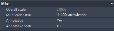
Straight out of ChatGPT providing both No & Yes versions MldAnoY.lsp MldAnoN.lsp
-
 I was considering a situation where a mechanical component is imported from another CAD platform as a collection of curves and splines rather than clean lines, arcs, and polylines. The geometry may look correct, but small deviations can cause problems when creating toolpaths, measuring profiles, or preparing manufacturing drawings. Converting everything into polylines with a fixed tolerance can also distort critical curves. How do you decide the right curve-fitting tolerance when converting imported geometry? Do you preserve the original splines, approximate them with arcs, or use another approach to maintain manufacturing accuracy?
-
Hi all, I've been looking into finding a way to change annotative text multileaders from yes to no via lisp and i've had no luck. does anybody know if its possible? not sure why its so difficult. i want to be able to remove (not to delete just change from yes to no) all objects with annotative text from a drawing including nested objects. (im running full version autocad 2026)

-
Fitting without collision
indiancad replied to Discus84's topic in AutoCAD 2D Drafting, Object Properties & Interface
Try using `REGION` and `INTERSECT` to check for collisions as you rotate and slide the box through the opening. This method is more accurate than using a circle. The `REGION` command helps define the shape of the box and `INTERSECT` checks if it overlaps with the opening. It gives results because it follows the exact shape of box instead of relying on a circle that might be too big or too small. You can test this by moving the box and checking for collisions at each step. It works well when the box is, at odd angles. Just make sure the box and the opening are properly defined as regions. -

Fitting without collision
lrm replied to Discus84's topic in AutoCAD 2D Drafting, Object Properties & Interface
@Discus84 I have found that when creating geometry to be used with the parametric feature it is best not to create any lines or polylines orthogonal to the world. E.g., Create you box somewhat rotated and then it's clearer what constraints you need, both dimensional and geometric constraints. -

Fitting without collision
Discus84 replied to Discus84's topic in AutoCAD 2D Drafting, Object Properties & Interface
It works as expected...I'm running Autocad clone now and it's hard to get the constraint definitions but this certainly works ! Thanks - Yesterday
-
A contrived exercise to demonstrate the performance considerations: (defun foo1 ( lst ) (vl-sort lst (function (lambda ( s1 s2 ) (compare (splitstr s1) (splitstr s2)) ) ) ) ) (defun foo2 ( lst ) (mapcar '(lambda ( n ) (nth n lst)) (vl-sort-i (mapcar 'splitstr lst) 'compare) ) ) (defun compare ( l1 l2 / x y ) (while (and l1 l2 (= (setq x (car l1)) (setq y (car l2)))) (setq l1 (cdr l1) l2 (cdr l2) ) ) (cond ( (null l1)) ( (null l2) nil) ( (and (numberp x) (numberp y)) (< x y) ) ( (numberp x)) ( (numberp y) nil) ( (< (strcase x) (strcase y))) ) ) (defun splitstr ( str ) (read (strcat "(" (vl-list->string (apply 'append (mapcar (function (lambda ( a ) (if (< 47 a 58) (list a) (list 34 a 34) ) ) ) (vl-string->list str) ) ) ) ")" ) ) ) _$ (setq mylist (makelist 100)) ("byo547swd" "niq983ocu" "aca823vdk" "wtq568rur" "phi902niq" "bjh526uzd" "rji359jxn" "qqv937rwf" "tug083pja" "gad189ena" "lte537pir" "laa124lqe" "pjd997nvz" "opt105nif" "lbg559zsq" "tpj226ohq" "jdo941odr" "pyl665lro" "hoi547oxb" "tke599mge" "tqm797yrt" "dlm480ido" "jlt529gio" "dtl751rtz" "lpi310zks" "rit617cpr" "qdf999kec" "lkz260ohj" "xlg106fuk" "dqj592rbs" "rza409lss" "phx280fll" "rft924rac" "xrt327nir" "mil320zdh" "sec951fzz" "hng963son" "bhm360nws" "whv768vre" "sub738cgn" "udp152qpy" "bfv499vpg" "bef375dxu" "sne299abt" "jwg218naf" "kul046lji" "opm274fep" "xqb135wrk" "vug239ccx" "yvk063bnl" "cca701lfg" "upy690bri" "nsj806ovt" "igt413wky" "ftw622pra" "jsm813cre" "fnd378khc" "utk011unn" "hkm488zlv" "naw752kdp" "gze062nrv" "ytt910gzi" "eeq942uez" "rbm719yzv" "adu204kgv" "voo553bzq" "qah335lvg" "oky453mna" "bye070dci" "uwt849qig" "nkg662cbj" "koy546cve" "fgp548fhm" "hxm087okh" "atb056yvr" "jxz680bdn" "ofc383clx" "ran801jgt" "dai951aut" "muc372eji" "dmv843wdj" "mwl251acq" "skn266edb" "stz033eih" "qbm300sjp" "tax196nfk" "uix079eqf" "evl716cui" "tjl236dov" "mod149kqp" "cai814mxb" "yyf245cfk" "occ503uit" "csd182gul" "jgs728fmy" "hga698aqi" "hfk752ize" "vra872olq" "bjm266zaq" "zva674kji") _$ (foo1 mylist) ("aca823vdk" "adu204kgv" "atb056yvr" "bef375dxu" "bfv499vpg" "bhm360nws" "bjh526uzd" "bjm266zaq" "bye070dci" "byo547swd" "cai814mxb" "cca701lfg" "csd182gul" "dai951aut" "dlm480ido" "dmv843wdj" "dqj592rbs" "dtl751rtz" "eeq942uez" "evl716cui" "fgp548fhm" "fnd378khc" "ftw622pra" "gad189ena" "gze062nrv" "hfk752ize" "hga698aqi" "hkm488zlv" "hng963son" "hoi547oxb" "hxm087okh" "igt413wky" "jdo941odr" "jgs728fmy" "jlt529gio" "jsm813cre" "jwg218naf" "jxz680bdn" "koy546cve" "kul046lji" "laa124lqe" "lbg559zsq" "lkz260ohj" "lpi310zks" "lte537pir" "mil320zdh" "mod149kqp" "muc372eji" "mwl251acq" "naw752kdp" "niq983ocu" "nkg662cbj" "nsj806ovt" "occ503uit" "ofc383clx" "oky453mna" "opm274fep" "opt105nif" "phi902niq" "phx280fll" "pjd997nvz" "pyl665lro" "qah335lvg" "qbm300sjp" "qdf999kec" "qqv937rwf" "ran801jgt" "rbm719yzv" "rft924rac" "rit617cpr" "rji359jxn" "rza409lss" "sec951fzz" "skn266edb" "sne299abt" "stz033eih" "sub738cgn" "tax196nfk" "tjl236dov" "tke599mge" "tpj226ohq" "tqm797yrt" "tug083pja" "udp152qpy" "uix079eqf" "upy690bri" "utk011unn" "uwt849qig" "voo553bzq" "vra872olq" "vug239ccx" "whv768vre" "wtq568rur" "xlg106fuk" "xqb135wrk" "xrt327nir" "ytt910gzi" "yvk063bnl" "yyf245cfk" "zva674kji") _$ (foo2 mylist) ("aca823vdk" "adu204kgv" "atb056yvr" "bef375dxu" "bfv499vpg" "bhm360nws" "bjh526uzd" "bjm266zaq" "bye070dci" "byo547swd" "cai814mxb" "cca701lfg" "csd182gul" "dai951aut" "dlm480ido" "dmv843wdj" "dqj592rbs" "dtl751rtz" "eeq942uez" "evl716cui" "fgp548fhm" "fnd378khc" "ftw622pra" "gad189ena" "gze062nrv" "hfk752ize" "hga698aqi" "hkm488zlv" "hng963son" "hoi547oxb" "hxm087okh" "igt413wky" "jdo941odr" "jgs728fmy" "jlt529gio" "jsm813cre" "jwg218naf" "jxz680bdn" "koy546cve" "kul046lji" "laa124lqe" "lbg559zsq" "lkz260ohj" "lpi310zks" "lte537pir" "mil320zdh" "mod149kqp" "muc372eji" "mwl251acq" "naw752kdp" "niq983ocu" "nkg662cbj" "nsj806ovt" "occ503uit" "ofc383clx" "oky453mna" "opm274fep" "opt105nif" "phi902niq" "phx280fll" "pjd997nvz" "pyl665lro" "qah335lvg" "qbm300sjp" "qdf999kec" "qqv937rwf" "ran801jgt" "rbm719yzv" "rft924rac" "rit617cpr" "rji359jxn" "rza409lss" "sec951fzz" "skn266edb" "sne299abt" "stz033eih" "sub738cgn" "tax196nfk" "tjl236dov" "tke599mge" "tpj226ohq" "tqm797yrt" "tug083pja" "udp152qpy" "uix079eqf" "upy690bri" "utk011unn" "uwt849qig" "voo553bzq" "vra872olq" "vug239ccx" "whv768vre" "wtq568rur" "xlg106fuk" "xqb135wrk" "xrt327nir" "ytt910gzi" "yvk063bnl" "yyf245cfk" "zva674kji") _$ (equal (foo1 mylist) (foo2 mylist)) T _$ (benchmark '((foo1 mylist) (foo2 mylist))) Benchmarking ..........Elapsed milliseconds / relative speed for 128 iteration(s): (FOO2 MYLIST).....1953 / 4.84 <fastest> (FOO1 MYLIST).....9453 / 1.00 <slowest>
-
If you're worried about the removal of duplicated elements when using (vl-sort), just use (vl-sort-i) to obtain the sorted indices and use them to order the original list - this has been solved/demonstrated many times over and is also typically far more performant when sorting lists for which the sort function would otherwise perform some manipulation of the list elements. _$ (setq mylist '(5 3 6 4 5 3 7 5)) (5 3 6 4 5 3 7 5) _$ (vl-sort mylist '<) (3 4 5 6 7) _$ (mapcar '(lambda ( n ) (nth n mylist)) (vl-sort-i mylist '<)) (3 3 4 5 5 5 6 7)
-
ZOMBIEKiILLER by Gilecad trying to remember converts proxy objects. Pretty sure link was here. Acad and Bricscad versions. Found "Simply search and download zombiekiller from app.autodesk.com this will delete all the proxy information in the drawing." Have you downloaded the show proxy objects patch from Autodesk ? 2000I may be a problem.
-

Fitting without collision
BIGAL replied to Discus84's topic in AutoCAD 2D Drafting, Object Properties & Interface
Did something similar for vehicle driveway checking, just a maybe make the box like 2mm smaller than true size and position and rotate, use intersectwith to see if the box and walls touch you will get nil if they dont.touch. Say stop when get points. -
This was created by Copilot, limited testing. and only sorts on single item. (defun BubblePass (lst / a b) (cond ((or (null lst) (null (cdr lst))) lst) ((> (car lst) (cadr lst)) (cons (cadr lst) (BubblePass (cons (car lst) (cddr lst))))) (t (cons (car lst) (BubblePass (cdr lst)))) ) ) (defun BubbleSort (lst / i) (repeat (length lst) (setq lst (BubblePass lst)) ) lst ) Asked about sort on 1st 2 items in list (defun QSORT2 (lst / pivot) (defun _less (a b) (or (< (car a) (car b)) (and (= (car a) (car b)) (< (cadr a) (cadr b))))) (if (cdr lst) (progn (setq pivot (car lst)) (append (QSORT2 (vl-remove-if-not '(lambda (x) (_less x pivot)) (cdr lst))) (list pivot) (QSORT2 (vl-remove-if-not '(lambda (x) (not (_less x pivot))) (cdr lst))) ) ) lst ) ) Limited testing.