All Activity
- Today
-
 Curzon joined the community
 -
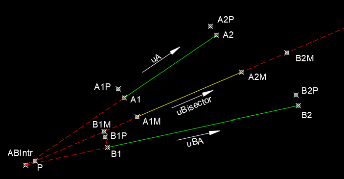
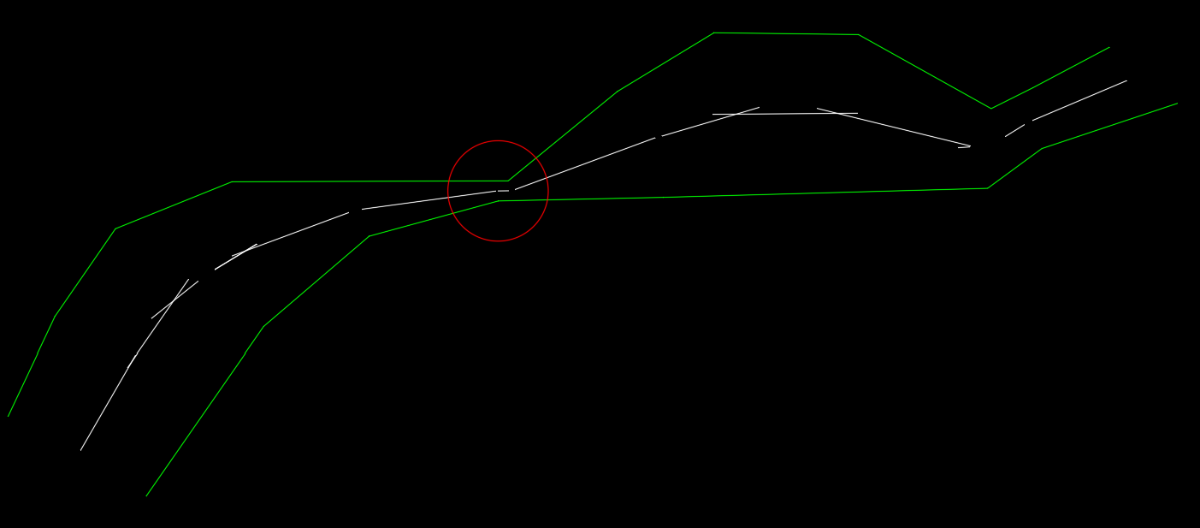
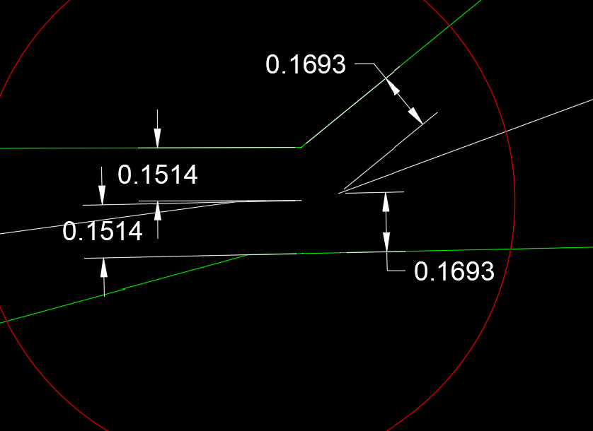
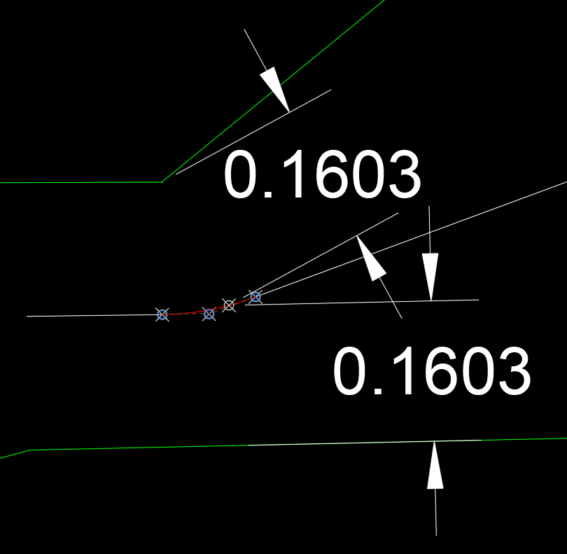
I have enjoyed the discussion of this thread. As I gave the task more thought and anaysis it became more clear that the task was not simple. As it appears that there is still no satisfacory solution I thought I would offer the following. The first goal for me was to create a function that would create a midline between two non parallel lines. The mid-lines extents should be a function of the given line segments. This function could then be used in a program that would step through the line segments of one of the polylines and search the other polyline for relevant segments. The function "midline" accepts four points. The first two points, A1 and A2, are the ends of one line sement while the thrid and fourth points, B1 and B2, are the ends of an opposing ilne segments. The diagram below details the variables in the function. The program uses vectors as I prefer them over angles which present, for me, a variety of problems. uA = unit vector in the diection from A1 to A2 uB = unit vector in the direction from B1 to B2 uBisector = unit vector in the direction of the angle bisector of uA and UB The ends of the two lines are projected onto the bisecting line defining 4 points, A1M, A2M, B1M, B2M. I debated which of the points to output for the line to be drawn. I first used the closest and furthest points from the intersecttion point ABIntr but I found it more helpful to use the two intermediate points (A1M and A2M in the example above). Here's an example of the results after manually steppng alone the polyline. Looking at the area circled in red we find: To fill the gap we need a curve that starts with a radius of 0.1514 and ends with a radius of 0.1693. This can be done with a spline or you may find it acceptable to extend the two lines to the point of intersection. The best way to create the spline is to use the Control Vertex Method and use the two endpoints and the imaginary point of intersecton for the middle CV. This ensures tangency to the two lines. As can be seen below the distance to a random point along the spline (red) agree! Run the program "test" and specify the end points of a line segment on one of the polylines, then the endpoints on a line segment on the opposing polyline. I have found the results very accurate and although it may not be used for creating the complete "hybrid " polyline it is helpful in finding the correct line for a specific segment.

- Yesterday
-
@JerryFiedler look at fanzy zone that is also part of powertoys. its the whole reason i got it when it first came out.
-
@BIGAL This may not be what the OP was looking for but this is an extremely useful tool. Thanks for posting the link. I keep my CAD window "full" size from start to finish. I simply do not change it since doing so messes with the ribbon, toolbars, etc. I often want another "clip" of a spreadsheet or notepad text (lisp program or some other list) visible while actually working in the CAD window. This tool does exactly that. Thanks again Alan for posting the link.
-
My one should find the centre between the shortest lines from polylines point to the other... not perpendicular so should give a reasonably curve.
-
 Vdietz joined the community
 -
 VictoriaJ joined the community
 -
 rcaldas joined the community
 -
And, VERY IMPORTANTLY, it should return the same result regardless of which reference polyline is processed first. In my opinion, this is the first requirement for the method to be consistent.
-
 CosmoIV joined the community
 -
15 years later I am annoyed by this effect too and This is one of the first links that shows up when searching for a solution. The system variable is MTextFixed. Changing it from 2 to 1 disables it.
-
Thank you @Steven P The problem with creating the centerline using perpendiculars is that even in straight sections, the centerline is not equidistant perpendicularly from the reference polylines (unless the reference polylines are parallel). This is the method I used manually, but I didn't achieve this goal.
-
Thanks @Steven P I guess you're right. Anyway, I'll try to keep this thread going a little longer to give others time to make their suggestions.
-
We used to have a 3rd party PDF printer - it also worked with all the office applications for example. Worked just the same as adding any other physical printer, might be a solution. However I thought LT had a PDF plotter as a part of the package
-
I think you didn't understand the point of this thread because you're not familiar with the original post.
-
I looked at the Autodesk site and as far as I know only AutoCAD for MAC (LT) 2026 is compatible with Tahoe which was just released September 2025. Can you print to an image file, that may work, or just see if Fedex/Kinkos can print the drawing file.
-
 Gio76 joined the community
 -
 animal1103 joined the community
 -
Notepad++ is my preference which has lisp with customizable colors, words looks like vlide but without its diagnostics.
-
Oops again. Didn't know '@' is the same - my bad. Still the offset of it amazes me.
-
BTW this is also included without a command initialize, just wish I new what/how to access that as with (getvar 'lastpoint)
-
Is it for Windows 11?
- Last week
-
Never before knew AutoCAD saved this info.. Please test as I'm still A2K.. Key "0" to get last point picked when asked by command where to start.. which also includes: *ANY.point.on.screen. Any other number [understood as 'from'] changes this location as offset.from that <dist+angle> toward the current mouse position. Another is to click on a live vertex, hit esc, now that point is the saved/usable coord as mentioned. Similar to the second point of command which is used as 'dist.from.lastpoint' toward mouse as you press 'enter'. ... Still learning so I'll contact here. This is certainly useful once you add it to your mental tools.of.trade. * ANY.point.on.screen also includes non.entity,bare loc.
-
Admin: It is this post
-
I lost the post but found the answer, the question was how to keep a notepad window always on top of the CAD window. I did a google and found a Microsoft product. Admin please move if find other post. https://learn.microsoft.com/en-us/windows/powertoys/always-on-top You need to download and install then restart but works, tried with Bricscad.
-

Lisp for to get y value of polyline based on datum value and line.
BIGAL replied to Ish's topic in AutoLISP, Visual LISP & DCL
Need a Plan dwg showing the line work etc this will give some clues about the extra points that you want highlite those points in the Plan dwg, to really get an proper answer need a full CIV3D dwg not just a output setcion so a CIV3D user can run the make long and cross sesctions. -
Looking for a LISP to evenly space polylines from their end points
BIGAL replied to Tamim's topic in AutoLISP, Visual LISP & DCL
"so that it works for "Y" direction movements as well." I did think about what happens if the objects are drawn on an angle, There may be a way by using work out the new points using a 90 angle off the existing points. Suddenly busy so not sure when will have time to do something. -
 lge joined the community
 -
I need to print a PDF so I can take the file to be printed at Fedex/Kinkos. I have AutoCAD LT 2021 for Mac. Computer recently upgraded to Tahoe OS. In trying to fix this I found that I seem to have two versions of the app: AutoCAD LT 2021 and AutoCAD LT 2021F. The 2021F, I think I understand, is the new version created by the upgrade to Tahoe. In the Plot window, the Print drop-down does not have the option for printing to PDF. There are only physical printers listed. The Save to PDF button at the bottom creates an Acrobat error and will not print. Export to PDF does not work. In addition, the Plot Style is set to Print As Displayed. I am not using .ctb because I can’t get one loaded at this point. The drop-down options for Plot Style are New, Import, Reveal in Finder. These are not working. (I want them to work eventually, but I have to get the PDF printed as soon as possible.) So setting the Plot Style to other than Print As Displayed can wait for now. I’m thinking this is a file path issue, but I have no idea how fix it. But maybe that's wrong. Thank you for any help.
-

Lisp request... trim (wall) lines with (column) multiple closed plines and circles
SLW210 replied to ilarch2016's topic in AutoLISP, Visual LISP & DCL
Use OVERKILL to remove the overlaps. -
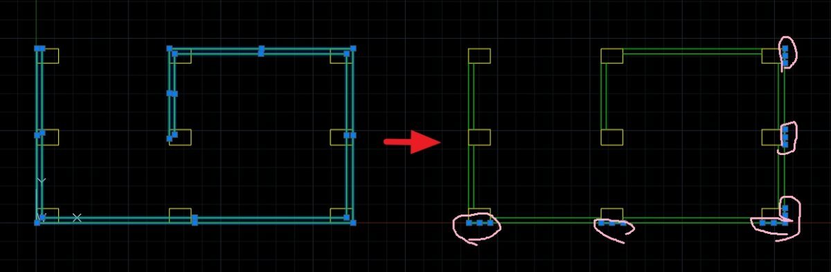
Dinner time but been playing with this for interest. Will leave this here to pick up next time.... This looks at both polylines and draws a point at the mid point between every point and the closest point on the other for each. Not quite there with it yet though, but might give an idea for later. The point list used for drawing the points isn't in order so drawing a line sometimes gives odd results - need to have a think how to set the order of these to draw the lines. Left this drawing the shortest distances between polyline points and lines just for my checking. One last thing for next time is to fix any arc segments.. but getting there. (defun c:PolyMD ( / acount MyPoly1 MypolyEnt1 MyPolyVert1 MyPoly2 MypolyEnt2 MyPolyVert2 pt pt1 pt2 Ptist1 PtList2 LinePt) (defun mAssoc ( key lst / result ) (foreach x lst (if (= key (car x)) (setq result (cons (cdr x) result)) ) ) (reverse result) ) ; end Massoc (defun midpt (p1 p2) (polar p1 (angle p1 p2) (/ (distance p1 p2) 2.) ) ) (defun LM:Unique ( l ) (if l (cons (car l) (LM:Unique (vl-remove (car l) (cdr l))))) ) (defun CtrCoo ( a / findctr a apt) ;;https://www.cadtutor.net/forum/topic/66091-centre-of-hatch/ (defun findctr (en / pt) (command "_.Zoom" "_Object" en "") (setq pt (getvar 'viewctr)) (command "_.Zoom" "_Previous") pt ) (setq ;;a (car (entsel "Select Rectangle: : ")) apt (findctr a) ) ) (defun MakePoint ( pt / ) (entmakex (list '(0 . "POINT") '(100 . "AcDbEntity") '(100 . "AcDbPoint") (cons 10 pt) )) ) (defun MakeLine (pt1 pt2 / ) (entmakex (list '(0 . "LINE") '(100 . "AcDbEntity") '(100 . "AcDbLine") (cons 10 pt1) (cons 11 pt2) )) ) ;; Create extract arcs from polyline defun for curves (setq MyPoly1 (car (entsel "\nSelect Polyline 1: "))) (setq MyPoly1Ent (entget MyPoly1)) (setq MyPoly1Vert (mAssoc 10 MyPoly1Ent)) (setq Poly1CtrCoo (CtrCoo MyPoly1)) (setq MyPoly2 (car (entsel "\nSelect Polyline 2: "))) (setq MyPoly2Ent (entget MyPoly2)) (setq MyPoly2Vert (mAssoc 10 MyPoly2Ent)) (foreach pt MyPoly1Vert (setq pt2 (vlax-curve-getclosestpointto MyPoly2 pt _none)) (makeline pt pt2) (setq PtList1 (cons (midpt pt pt2) PtList1)) ) ; end foreach (foreach pt MyPoly2Vert (setq pt1 (vlax-curve-getclosestpointto MyPoly1 pt _none)) (makeline pt pt1) (setq PtList1 (cons (midpt pt pt1) PtList1)) ;;not sure which to go with (setq PtList2 (cons (midpt pt pt1) PtList2)) ) ; end foreach (setq PtList1 (lm:unique (reverse PtList1))) (foreach pt PtList1 (Makepoint pt) ) ;;Work out if midpoints outside of exterior polyline (in case of complicated shapes) ;;Work out order of points to link together ;;Work out polyline bulges )
-
 Terry B joined the community
 -

Lisp request... trim (wall) lines with (column) multiple closed plines and circles
ilarch2016 replied to ilarch2016's topic in AutoLISP, Visual LISP & DCL
I follow your instructtion. and do the other test, flattened it befor running TICS ,make sure they are flat. but there are still some overlaping lines left . I am confused... lisp test-V2.dwg
-
Lisp request... trim (wall) lines with (column) multiple closed plines and circles
ilarch2016 replied to ilarch2016's topic in AutoLISP, Visual LISP & DCL
OK!! Thanks you so much for remind me.