All Activity
- Today
-
 lge joined the community
 -

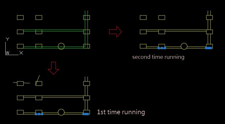
Lisp request... trim (wall) lines with (column) multiple closed plines and circles
SLW210 replied to ilarch2016's topic in AutoLISP, Visual LISP & DCL
Use OVERKILL to remove the overlaps. -
Dinner time but been playing with this for interest. Will leave this here to pick up next time.... This looks at both polylines and draws a point at the mid point between every point and the closest point on the other for each. Not quite there with it yet though, but might give an idea for later. The point list used for drawing the points isn't in order so drawing a line sometimes gives odd results - need to have a think how to set the order of these to draw the lines. Left this drawing the shortest distances between polyline points and lines just for my checking. One last thing for next time is to fix any arc segments.. but getting there. (defun c:PolyMD ( / acount MyPoly1 MypolyEnt1 MyPolyVert1 MyPoly2 MypolyEnt2 MyPolyVert2 pt pt1 pt2 Ptist1 PtList2 LinePt) (defun mAssoc ( key lst / result ) (foreach x lst (if (= key (car x)) (setq result (cons (cdr x) result)) ) ) (reverse result) ) ; end Massoc (defun midpt (p1 p2) (polar p1 (angle p1 p2) (/ (distance p1 p2) 2.) ) ) (defun LM:Unique ( l ) (if l (cons (car l) (LM:Unique (vl-remove (car l) (cdr l))))) ) (defun CtrCoo ( a / findctr a apt) ;;https://www.cadtutor.net/forum/topic/66091-centre-of-hatch/ (defun findctr (en / pt) (command "_.Zoom" "_Object" en "") (setq pt (getvar 'viewctr)) (command "_.Zoom" "_Previous") pt ) (setq ;;a (car (entsel "Select Rectangle: : ")) apt (findctr a) ) ) ;; Create extract arcs from polyline defun for curves (setq MyPoly1 (car (entsel "\nSelect Polyline 1: "))) (setq MyPoly1Ent (entget MyPoly1)) (setq MyPoly1Vert (mAssoc 10 MyPoly1Ent)) (setq Poly1CtrCoo (CtrCoo MyPoly1)) (setq MyPoly2 (car (entsel "\nSelect Polyline 2: "))) (setq MyPoly2Ent (entget MyPoly2)) (setq MyPoly2Vert (mAssoc 10 MyPoly2Ent)) (foreach pt MyPoly1Vert (setq pt2 (vlax-curve-getclosestpointto MyPoly2 pt _none)) (setq PtList1 (cons (midpt pt pt2) PtList1)) ) ; end foreach (foreach pt MyPoly2Vert (setq pt1 (vlax-curve-getclosestpointto MyPoly1 pt _none)) (setq PtList1 (cons (midpt pt pt1) PtList1)) ;;not sure which to go with (setq PtList2 (cons (midpt pt pt1) PtList2)) ) ; end foreach (setq PtList1 (lm:unique (reverse PtList1))) ; (setq LinePt (cons (car PtList1) LinePt)) ; (setq PtList1 (vl-remove LinePt PtList1)) ; (setq acount (length PtList1)) ; (while (> acount 0) ;;;https://www.cadtutor.net/forum/topic/63206-get-closest-point-to-new-point-from-a-list/ ;(setq rtnpt (car (vl-sort PtList1 (function (lambda ( a b ) (< (distance (car LinePt) a) (distance (car LinePt) b))))))) ; (if (= rtnpt nil) ; () ; (setq LinePt (cons rtnpt LinePt)) ; ) ; (setq PtList1 (vl-remove rtnpt PtList1)) ; (setq acount (- acount 1)) ; ) ; end while ; ;(setq acount 0) ;(while (< acount (- (length LinePt) 1)) ; (command "line" (nth acount LinePt) (nth (+ acount 1) LinePt) "") ; (setq acount (+ acount 1)) ;) ;; (foreach pt LinePt ;; (command "point" pt) ;; ) )
-
 Terry B joined the community
 -

Lisp request... trim (wall) lines with (column) multiple closed plines and circles
ilarch2016 replied to ilarch2016's topic in AutoLISP, Visual LISP & DCL
I follow your instructtion. and do the other test, flattened it befor running TICS ,make sure they are flat. but there are still some overlaping lines left . I am confused... lisp test-V2.dwg
-
 Zalim joined the community
 -
Lisp request... trim (wall) lines with (column) multiple closed plines and circles
ilarch2016 replied to ilarch2016's topic in AutoLISP, Visual LISP & DCL
OK!! Thanks you so much for remind me. -
 DesmondKruger joined the community
 -

Create 3 Center Curves for Polylines
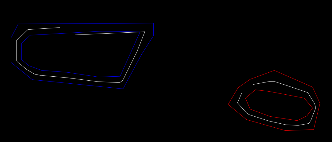
pallas replied to broncos15's topic in AutoLISP, Visual LISP & DCL
Thank you for your help. I managed to figure out where I was doing it wrong (I defined the values after the point where they were already used/called upon, didn't notice, so it was a simple matter or moving it higher, to the start of the code). The LISP does what I need it to do now, however I did encounter some issues with extreme cases, like a sharp angle (couple of degree) between the two lines/tangents - comment for future users -
 atefovic joined the community
 -

Create 3 Center Curves for Polylines
Steven P replied to broncos15's topic in AutoLISP, Visual LISP & DCL
Just for fun, a slight different way to set variables, I like the dotted pair listing to tie in variable name and its short description. Could be expanded as basic lists with the last item being the 'get' function (string, int, distance....) for different types using read and eval [ (list "ard" "Approach Radius" "getDist") ] (defun c:setvariables ( / acount ard crd erd aof eof ) (setq VariablesList (list (cons "ard" "Approach Radius") (cons "crd" "Center Radius") (cons "erd" "End Radius") (cons "aof" "Approach Offset") (cons "eof" "Tie In Offet") )) ; end list, end setq (foreach n VariablesList (setq MyX (getDist (strcat "\nSet " (cdr n) ": "))) (eval (read (strcat "(setq " (car n) " " (vl-princ-to-string MyX) ")" ))) ) ; end foreach ) (defun c:setvariables ( / acount ard crd erd aof eof ) (setq VariablesList (list (list "ard" "Approach Radius" "getdist") (list "crd" "Center Radius" "getdist") (list "erd" "End Radius" "getdist") (list "aof" "Approach Offset" "getdist") (list "eof" "Tie In Offet" "getdist") )) ; end list, end setq (foreach n VariablesList (setq MyX ( (eval (read (last n))) (strcat "\nSet " (cadr n) ": "))) (eval (read (strcat "(setq " (car n) " " (vl-princ-to-string MyX) ")" ))) (if (= (last n) "getstring") ; fix for strings (eval (read (strcat "(setq " (car n) " \"" (vl-princ-to-string MyX) "\")" ))) ) ) ; end foreach ) Couple of edits for typos -
Create 3 Center Curves for Polylines
SLW210 replied to broncos15's topic in AutoLISP, Visual LISP & DCL
You could just modify the LISP to store the last inputs. -
Does very well on some examples, but fails on a couple. From OPs original drawing (this one has given me problems as well) and a few shapes I made it didn't close the centerline.
-
Lisp request... trim (wall) lines with (column) multiple closed plines and circles
Steven P replied to ilarch2016's topic in AutoLISP, Visual LISP & DCL
For future reference and to follow on from SLW210, I'd perhaps only share the relevant information - seeing your drawing has a lot of layouts with borders, company information and so on, all good but maybe not always the best policy to share publicly. Purged, overkilled and so on to remove any company information that might be hidden too -
Lisp request... trim (wall) lines with (column) multiple closed plines and circles
SLW210 replied to ilarch2016's topic in AutoLISP, Visual LISP & DCL
The LISP worked on your original drawing, after I flattened it. You have issues with that drawing. You need to set the Current Layer to the one you want. -
Lisp for to get y value of polyline based on datum value and line.
Steven P replied to Ish's topic in AutoLISP, Visual LISP & DCL
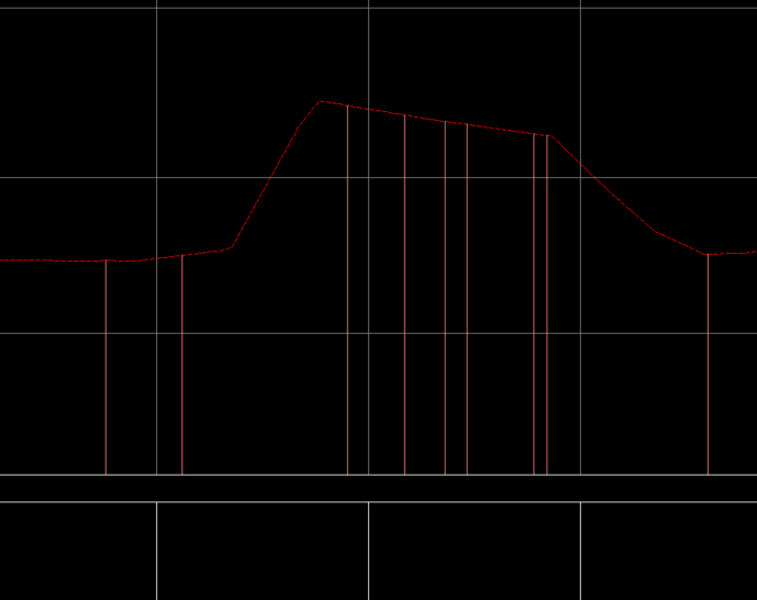
For my long sections I tend to create a block for the long section itself and then scale the X and Y axis to whatever scales I want ( I tend to use a Y scale of 5x, and X at 1x ) - that makes the analysis easier This is what I use. Select the surface profile Select the route / Datum line (I use this to measure the designed buried depths for new services) Loop to select the distance marker / indicator and then its associated text to update If I was doing this I would copy your vertical lines and associated texts to the points you want. Extend or trim these lines to the surface polyline then run this LISP to complete the texts. Can be a bit long to do a really long long section but I don't do so many of these to make the coding worth selecting everything all at once... so for now select all one at a time (defun c:LSBuriedDepth ( / ) (defun LM:intersections ( ob1 ob2 mod / lst rtn ) ; Lee Mac (if (and (vlax-method-applicable-p ob1 'intersectwith) (vlax-method-applicable-p ob2 'intersectwith) (setq lst (vlax-invoke ob1 'intersectwith ob2 mod)) ) ; end and (repeat (/ (length lst) 3) (setq rtn (cons (list (car lst) (cadr lst) (caddr lst)) rtn) lst (cdddr lst) ) ; end setq ) ; end repeat ) ; end if (reverse rtn) ) ; end defun (defun inter ( Ent1 Ent2 / obj1 obj2 ) ;Lee Mac (setq obj1 Ent1) (setq obj2 Ent2) (foreach pnt (LM:intersections (vlax-ename->vla-object obj1) (vlax-ename->vla-object obj2) acextendOTHERENTITY) (setq pt pnt) ) ; end foreach pt ) ; end defun (defun LStext ( n / EndLst ent entlst) ;updates text to 'n' (setq EndLst "No") (while (= EndLst "No") ;;loop till enter or space (progn (setvar 'errno 0) (setq ent (car (nentsel (strcat "\nSelect text to change")))) (cond ( (= 7 (getvar 'errno)) ;a (princ "\nMissed, try again.") ) ;end cond a ( (and (/= (cdr (assoc 0 (entget ent))) "TEXT")(/= (cdr (assoc 0 (entget ent))) "MTEXT") ) (princ "\nMissed, try again") ) ( ;'t' (setq entlst (entget ent)) (setq entlst (subst (cons 1 n) (assoc 1 entlst) entlst)) (entmod entlst) (entupd ent) (setq EndLst "Yes") ) ;end cond b ) ;end Cond ) ;end progn ) ;end while (princ) ) ; end defun ;;End subfunctions (setq Ent1 (car (nentsel "\nSelect Surface Line (explode Blocks)"))) (setq Ent2 (car (nentsel "\nSelect Route or Datum Line (explode Blocks)"))) (while (setq Ent3 (car (entsel "\nSelect Distance Marker"))) ;; (setq Int1 (inter Ent1 Ent3)) ;; (setq Int2 (inter Ent2 Ent3)) (setq MyDist (- (cadr (inter Ent1 Ent3)) (cadr (inter Ent2 Ent3)))) ; Adjust here MyDist to acount for any scaling factors (setq MyDist (rtos MyDist 2 3)) (LStext (vl-princ-to-string MyDist)) ) ; end while ) -
that would be a windows thing rather than a CAD (or any other application) thing. Best I can think off would be to resize the windows so both are shown that way. Problem with doing it via lisp is whatever you are using to display the text would be closed or hidden as you do a CAD command, though perhaps a custom tool bar might work which just shows the text
-
Hi, I have a feeling this question has never been asked here. I have a Lisp that reads the drawing, writes a text file and opens it with Notepad. But I would like to be able to work with AutoCAD while keeping the contents of the file visible. Is there any Lisp that can do this?
-
 hly joined the community
 -

Lisp for to get y value of polyline based on datum value and line.
Saxlle replied to Ish's topic in AutoLISP, Visual LISP & DCL
Definitely, there will be bunch of overlapping texts. But, I think the problem is in the "grid", the equidistants are not equal and elevations can't be obtained. As I mentioned: I'm not familiar with working in Civil 3D, so I can't help here further. -
Looking for a LISP to evenly space polylines from their end points
Saxlle replied to Tamim's topic in AutoLISP, Visual LISP & DCL
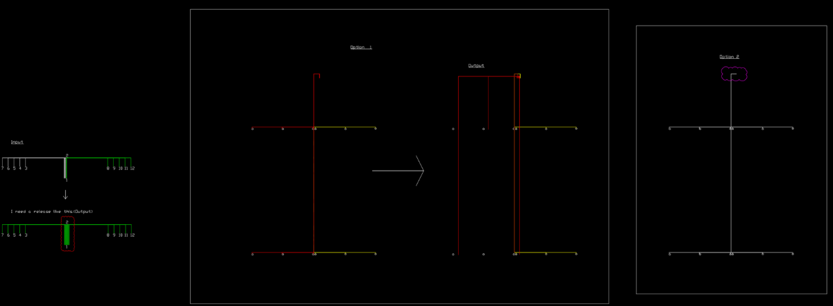
Hey @Tamim, Glad it works for the "based concept". But, I can't figure out "Option 1" and "Option 2", it's really messy to understand what I need to accomplish (because there is a bunch of overlapping polylines).If you can provide a clear, detailed, explanation, I will try to fix the code so that it works for "Y" direction movements as well. Best regards. -
Looking for a LISP to evenly space polylines from their end points
Saxlle replied to Tamim's topic in AutoLISP, Visual LISP & DCL
Hey @BIGAL, I used a "base point" to avoid determinanting is the polyline drawn CCW or CW, easier, and then calculated new position of the polylines based on choosing "Left or Right", which means the "X" coord will change in that side. Also, I supose that the polyline can have many vertexes and drawed randomly (not only straight lines). Bassicly, this is the one of the concept how it can be done. I figured out the easiest way is sorting by the Lengths of the polyline, from min to max, to get a proper order. Can't wait to see your solution, maybe find something interesting inside the code . -
Lisp request... trim (wall) lines with (column) multiple closed plines and circles
ilarch2016 replied to ilarch2016's topic in AutoLISP, Visual LISP & DCL
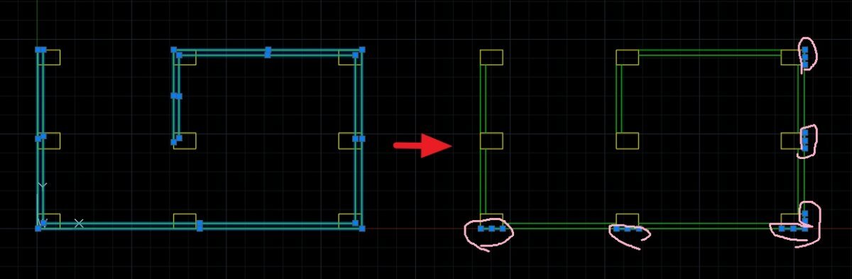
I wish the result could be keeping green lines in the original layer, and remove the overlaping -

Looking for a LISP to evenly space polylines from their end points
Tamim replied to Tamim's topic in AutoLISP, Visual LISP & DCL
@Saxlle Thanks for the code. It’s working based on the concept. Please check the DWG file. I’ve worked on Option 1 and Option 2. In Option 1, I planned the left-side spacing as per your video input, all settings are done, but the output line looks different. Please advise on this. Option 2 is another concept where the top side moves up and down, similar to the left and right adjustments line shifting.dwg
-
Thought we were getting tolled when i saw @GP_ GIF had to double take on the original posted dwg.
- Yesterday
-

Looking for a LISP to evenly space polylines from their end points
BIGAL replied to Tamim's topic in AutoLISP, Visual LISP & DCL
Hi @Saxlle started to do something found the plines are drawn in a CCW or CW direction for left right so I am going to set that to one direction I look at the length of 1st and 3rd section to work out which end to change, so no need for Left or right. The start point is (/ offset 2) left or right. So don't need user enter base_point. I just worked out the new X values for the pline and use (vlax-put obj 'coordinates pts) to redo the pline no need to actually draw a new pline. use (vlax-get obj 'coordinates) for the XY values of the pline. Yes need a ssget but looking at a drag over the plines for offset order. So yes would do twice for sample. NOTE my code is based on the sample dwg provided, got about 1/2 way when posting this, hopefully later today will post my attempt. -
Lisp for to get y value of polyline based on datum value and line.
BIGAL replied to Ish's topic in AutoLISP, Visual LISP & DCL
If your trying to get the levels shown by the Brown lines color 11 you will end up with a mess of overlapping text. In this image looks like a road etc so want levels. Civ3D at times lacks some functionality, it looks like you have used a built in grid option for plotting long section etc. You may be better off going back to your CAD dealer and ask for help about how to set up CIV3D to meet your needs. I know in other add on software can use different methods to set what points get levels plotted, A lot of times the complexity of using CIV3D is a problem and finding the solution is difficult. Maybe post this question into the CIV3D forum. I stopped using CIV3D many years ago so can not help.
-
The issue wasn't retention of the stacking. In version 5.0c at least the height checkbox didn't remove the text overide whilst the copy of 5.0d I found did.
-

Create 3 Center Curves for Polylines
mhupp replied to broncos15's topic in AutoLISP, Visual LISP & DCL
replace ;;----------------------------------------------------------------------;; (vl-every '(lambda ( sym msg ) (initget 6) (set sym (getdist msg))) '(ard crd erd aof eof) '("\nSpecify approach radius: " "\nSpecify center radius: " "\nSpecify end radius: " "\nSpecify approach offset: " "\nSpecify tie-in offset: " ) ) ;;----------------------------------------------------------------------;; with ;;----------------------------------------------------------------------;; (setq crd (getdist "\nMiddle Radius: ") ard (* 2 crd) ; Approach radius erd (* 3 crd) ; Exit radius aof (* 0.0375 crd) ; Approach offset eof (* 0.1236 crd) ; Exit offset ) ;;----------------------------------------------------------------------;; Tho that is pretty cool way to set a bunch of variables with lambda -

Impossible to change attribute text size within dynamic block
jamami replied to jamami's topic in AutoCAD Drawing Management & Output
Thank you For the suggestion. I believe the only solution to solve this is Lisp or similar . i need to change the text height without exploding the dynamic and sub blocks. the reason for this is that this beam block does not work alone . There are several other blocks that work alongside it . All attributed in a similar way . i need the ability to control the text height via the text style name and the only way to do this is via an intrusive script . -
Lisp request... trim (wall) lines with (column) multiple closed plines and circles
ilarch2016 replied to ilarch2016's topic in AutoLISP, Visual LISP & DCL
I give it a try. this is what I got.This routine goes wrong with overlapping. and change the layer(green to yellow) lisp request_tics result.dwg