All Activity
- Past hour
-

Add to the code the ability to create layouts for non-standard formats
Nikon replied to Nikon's topic in AutoLISP, Visual LISP & DCL
It is enough that the frames are just on one layer. I will try to add squares and formats to the code, but it seems to me that a different approach is needed for non-standard formats. -

Add to the code the ability to create layouts for non-standard formats
pkenewell replied to Nikon's topic in AutoLISP, Visual LISP & DCL
Are these the actual names of the Paper sizes in the pc3 file? The squares in your example file are just the paper sizes. You need to know the Frame layer, and the size range of the Frames that create your viewports. In any case - you should have all the information you need to do it yourself. as I said in the above to lay it out more clearly: 1) You need a range of AREA to be within on the frames. For example, on your "A4x3", (297 x 630) = 187110. Your range for the "square" variable should be a min and max with this value in the middle, such as 187110 - 10000 = 177110 "(> Square 177110)" and 187110 + 10000 = 197110 "(< Square 197110)" 2) each added condition should have the exact name of the Custom paper size: ((and (> Square 177110) (< Square 197110))(vla-put-ConfigName Layout "DWG To PDF.pc3")(vla-put-CanonicalMediaName Layout "_A4x3_(297.00_x_630.00_MM)")) ALSO: 3) You must have a unique Layer for the Frame polylines or blocks, something like "MyPaperSizeFrameLayer", or anything, as long as it is unique to the frames. -
 h.elbattani joined the community
 -
Add to the code the ability to create layouts for non-standard formats
Nikon replied to Nikon's topic in AutoLISP, Visual LISP & DCL
I have attached a dwg example. -
Add to the code the ability to create layouts for non-standard formats
pkenewell replied to Nikon's topic in AutoLISP, Visual LISP & DCL
The condition lines I added were just examples of how to add more sizes. As long as you know the areas and the name of the paper size, you should be able to add them. The "Square" variable as i understand it, is the min and max AREA of the frame you select (Length x Width), for the condition to select the paper size. This depends on what you are selecting for the frame to define the paper size. How would I know, if I don't have an example of what you are selecting? - Today
-
Add to the code the ability to create layouts for non-standard formats
Nikon replied to Nikon's topic in AutoLISP, Visual LISP & DCL
I don't use such formats: "ISO_full_bleed_2A0_(1189.00_x_1682.00_MM)" "ISO_full_bleed_4A0_(1682.00_x_2378.00_MM)" The sizes of the formats are listed in the list "List of non-standard formats". I don't understand how to get these numbers: (> Square 59251) (< Square 65488) (> Square 118503) (< Square 130977) and how will they help you create a non-standard layout? -
Hello everyone! Please take a look at this.
pkenewell replied to sd2006's topic in AutoLISP, Visual LISP & DCL
You must've copied the changes into your code incorrectly. "RH: DXF" is already defined in your original code. (defun rh:dxf (code lst) (cdr (assoc code lst))) Attached is your original code with @mhupp's change: (defun rh:dxf (code lst) (cdr (assoc code lst))) (defun c:aa ( / cmde ent e_typ e_lst area vtx x_lst y_lst z_lst x_pt y_pt z_pt c_lst v_lst ss sum) (cond ( (/= 0 (getvar 'cmdecho)) (setq cmde (getvar 'cmdecho)) (setvar 'cmdecho 0) ) ) (while (setq ss (ssget "_+.:E:S" '((0 . "POLYLINE,LWPOLYLINE") (-4 . "<OR") (70 . 1) (70 . 3) (70 . 5) (-4 . "OR>") ) )) (setq ent (ssname ss 0) e_typ (rh:dxf 0 (setq e_lst (entget ent))) area (getpropertyvalue ent "area") v_lst nil ) (cond ( (= e_typ "POLYLINE") (setq ent (entnext ent) vtx (rh:dxf 10 (entget ent)) ) (if (< (length vtx) 3) (setq vtx (reverse (cons 0.0 (reverse vtx))))) (while (/= "SEQEND" (cdr (assoc 0 (entget ent)))) (setq v_lst (cons vtx v_lst) ent (entnext ent) vtx (rh:dxf 10 (entget ent)) ) (if (< (length vtx) 3) (setq vtx (reverse (cons 0.0 (reverse vtx))))) ) (setq x_pt (/ (apply '+ (mapcar '(lambda (x) (car x)) v_lst)) (length v_lst)) y_pt (/ (apply '+ (mapcar '(lambda (x) (cadr x)) v_lst)) (length v_lst)) ) (if (= (setq sum (apply '+ (mapcar '(lambda (x) (caddr x)) v_lst))) 0.0) (setq z_pt 0.0) (setq z_pt (/ sum (length v_lst))) ) ) ( (= e_typ "LWPOLYLINE") (setq z_pt (rh:dxf 38 e_lst)) (foreach pr e_lst (if (= (car pr) 10) (setq v_lst (cons (cdr pr) v_lst))) ) (setq x_pt (/ (apply '+ (mapcar '(lambda (x) (car x)) v_lst)) (length v_lst)) y_pt (/ (apply '+ (mapcar '(lambda (x) (cadr x)) v_lst)) (length v_lst)) ) ) ) (setq c_lst (list x_pt y_pt z_pt)) (entmakex (list (cons 0 "MTEXT") (cons 100 "AcDbEntity") (cons 100 "AcDbMText") (cons 10 c_lst) (cons 40 (getvar 'textsize)) (cons 71 5) (cons 72 5) (cons 1 (strcat (rtos (/ area 1000000.0) 2 2) "m" (chr 0178))) ; (cons 1 (strcat (rtos (/ area 1000000.0) 2 2) "m²")) ; (cons 1 (rtos (/ area 1000000.0) 2 3)) ; If you don't need the suffix "m²" ) ) ) (if cmde (setvar 'cmdecho cmde)) ) -

Losing selected objects when zooming/panning etc
SLW210 replied to TxArcht81's topic in AutoCAD 2D Drafting, Object Properties & Interface
When this thread was started in 2014, it absolutely was the way AutoCAD worked, SELECTIONOFFSCREEN is only available in AutoCAD 2018 and newer. This has already been mentioned in this thread as well. -
Add to the code the ability to create layouts for non-standard formats
pkenewell replied to Nikon's topic in AutoLISP, Visual LISP & DCL
@Nikon While I don't know this routine, and don't recognize the Paper Sizes you have specified. The change would have to do with this section I think (see below). I added a couple condition lines for standard layouts "ISO full bleed 2A0" and "ISO full bleed 4A0" that are in my standard "DWG to PDF.PC3" file. I don't know what determines the area of the viewports though, (it seems that it is an object you select), so I am guessing at the area range of the viewport sizes. (cond ((and (> Square 59251) (< Square 65488)) (vla-put-ConfigName Layout "DWG To PDF.pc3") (vla-put-CanonicalMediaName Layout "ISO_full_bleed_A4_(297.00_x_210.00_MM)")) ((and (> Square 118503) (< Square 130977)) (vla-put-ConfigName Layout "DWG To PDF.pc3") (vla-put-CanonicalMediaName Layout "ISO_full_bleed_A3_(420.00_x_297.00_MM)")) ((and (> Square 237006) (< Square 261954)) (vla-put-ConfigName Layout "DWG To PDF.pc3") (vla-put-CanonicalMediaName Layout "ISO_full_bleed_A2_(594.00_x_420.00_MM)")) ((and (> Square 474012) (< Square 523908)) (vla-put-ConfigName Layout "DWG To PDF.pc3") (vla-put-CanonicalMediaName Layout "ISO_full_bleed_A1_(841.00_x_594.00_MM)")) ((and (> Square 948024) (< Square 1047816)) (vla-put-ConfigName Layout "DWG To PDF.pc3") (vla-put-CanonicalMediaName Layout "ISO_full_bleed_A0_(841.00_x_1189.00_MM)")) ((and (> Square 1949898) (< Square 2049898)) (vla-put-ConfigName Layout "DWG To PDF.pc3") (vla-put-CanonicalMediaName Layout "ISO_full_bleed_2A0_(1189.00_x_1682.00_MM)")) ((and (> Square 3949796) (< Square 4049796)) (vla-put-ConfigName Layout "DWG To PDF.pc3") (vla-put-CanonicalMediaName Layout "ISO_full_bleed_4A0_(1682.00_x_2378.00_MM)")) (T (vla-put-ConfigName Layout "None")) ; Default to No plotter for non-standard sizes ) -

AutoCAD 2027: Redefining How You Create, Collaborate, and Deliver
The AutoCAD Blog posted a topic in AutoCAD Blogs
AutoCAD 2027 delivers a connected, intelligent design experience that helps you move faster, collaborate with confidence, and focus on the work that matters most. This release helps you and your team maintain drawing standards, reduce time spent fixing geometry issues, and collaborate on shared DWG files without the conflicts of traditional file locking. With Autodesk AI-powered guidance, automated geometry cleanup, and cloud-connected workflows through Forma Data Management, AutoCAD 2027 helps you coordinate changes more easily and keep projects moving forward. Whether you’re working solo or across distributed teams, AutoCAD 2027 is designed to help you create with greater clarity, speed, and control. If you’re eager to explore the latest AI-powered capabilities introduced in this release, open the Autodesk Access application to start your update now! <?xml encoding="utf-8" ?> Work smarter with Autodesk AI AutoCAD 2027 introduces a new level of AI-powered workflows that help reduce friction and surface the right guidance at the right time. New Autodesk Assistant (tech preview) <?xml encoding="utf-8" ?> Autodesk Assistant delivers intelligent, in-context guidance powered by Autodesk AI without disrupting your design flow, helping you and your team maintain consistency and quality with less manual effort. In AutoCAD 2027, you can use conversational prompts to validate drawings against your organization’s own CAD standards, by uploading a reference file and checking designs against it, helping to surface CAD standards issues earlier and making it easier to catch problems during the design process. This experience is enabled by Autodesk Assistant beginning to leverage Model Context Protocol (MCP), which helps it better understand what you’re working on and what you’re trying to accomplish. This enables more situational, relevant responses directly inside AutoCAD. In this release, that capability is focused on alignment with CAD standards. A truly collaborative design experience As projects grow more complex and teams become more distributed, collaboration can’t be an afterthought. AutoCAD 2027 delivers new ways to work together securely and in parallel across desktop, web, and mobile. Forma Data Management Essentials now included with a standalone subscription <?xml encoding="utf-8" ?> With AutoCAD 2027, Forma Data Management Essentials is now included with standalone AutoCAD subscriptions, representing a significant added value for AutoCAD users. With this release, Forma is no longer a future vision: it’s now here, across the AutoCAD features you and your team use every day. In AutoCAD, Forma Data Management Essentials enables essential collaboration in a shared project environment where teams can view and markup 2D and 3D models, track issues, apply folder-level permissions, and share files with controlled access and clear version visibility. This brings cloud-based DWG storage, version history, and access control directly into AutoCAD workflows that you’re already familiar with. Whether you’re a drafter, designer, architect, engineer, or a CAD manager, it is well suited for small and mid-sized architecture and engineering firms, civil design practices, specialty consultants, and growing teams that need more structured collaboration and improved information exchange across projects. Shared drawings managed in the cloud can now take advantage of advanced collaboration features like Checkout, multi-user markup, and Connected References, supporting parallel work while keeping your data easily accesible. Introducing Checkout: Parallel work without the conflicts <?xml encoding="utf-8" ?> Checkout finally introduces a new way for teams to collaboratively make controlled edits to the same DWG file at the same time when stored in Forma Data Management. Instead of locking entire drawings, contributors can check out only the geometry they need to modify, letting you make changes in an isolated editing environment and safely merge them back when you’re ready. The result? No more unnecessary extra files just for editing, no accidental overwrites, and smoother collaboration especially on complex drawings with multiple contributors. Connected References and Connected Support Files Managing references and support files is easier and more reliable with deeper cloud connectivity in this release. Connected References reserve Xref integrity for drawings stored in Forma Data Management. When referenced files are moved or renamed, AutoCAD detects the change and suggests automatic repairs directly from the Xref palette. With a single click, all your references can be restored. <?xml encoding="utf-8" ?> Connected Support Files give CAD managers centralized control over cloud-managed support files, now enhanced to support tool palettes and CUI customizations for greater flexibility. With project-aware tool palettes and CUI, the right resources load automatically with each drawing, improving consistency and scalability across teams. In Forma Data Management, support files can be managed directly through the .autodesk.support folder within a project via a new “Manage Support Files” button that launches a configuration dialog. <?xml encoding="utf-8" ?> Cleaner drawings, faster workflows AutoCAD 2027 continues to focus on everyday productivity, helping you spend less time fixing issues and more time designing. Automatically Find and Fix Errors with Geometry Cleanup <?xml encoding="utf-8" ?> Geometry Cleanup automatically identifies common geometry issues such as gaps, overshoots, undershoots, and misaligned angles, then suggests targeted fixes to resolve them. By streamlining error detection and correction, this tool reduces manual cleanup, improves drawing quality, and makes files more reliable for downstream workflows. Performance and visualization improvements Expanded support for the Graphics System Framework (GSF) improves performance and reliability across AutoCAD’s 3D workflows. With smoother navigation, broader 3D coverage, and support for Realistic visual styles, materials, and lighting, AutoCAD 2027 delivers more consistent and responsive 3D visualization. Stronger workflows with AutoCAD on the web AutoCAD on the web continues to evolve into a powerful extension of desktop workflows, especially for collaboration and coordination. Issues, plotting, and sheet set improvements Forma Data Management Issues integration allows you to view, create, and resolve issues directly within drawings, keeping feedback visible and actionable. <?xml encoding="utf-8" ?> Plot improvements make it easier to save plots directly to the cloud, rename files, choose storage locations, preview PDFs, and confidently deliver final output. Sheet Set Manager improvements fully adopt Connected Support Files, with enhanced templates, workflows, and reliability that make sheet management better suited for everyday production work. <?xml encoding="utf-8" ?> Integration with Forma Board Included as part of access to Forma, AutoCAD on the web now integrates with Forma Board, connecting detailed CAD drafting with collaborative early-design workflows. Teams can view and edit DWG files within a shared canvas, keeping documentation aligned with concept development and design storytelling from early planning through detailed design. Start exploring AutoCAD 2027 AutoCAD 2027 is more than a feature update. It’s a step towards a more connected, intelligent, and collaborative design experience. From Autodesk AI-powered assistance and cleaner drawings to cloud-enabled collaboration across desktop, web, and mobile, this release is designed to help you work with confidence at every stage of your project. Download a 15-day free trial of AutoCAD 2027 today and see how these new capabilities can help you focus on what matters most: creating better designs, faster. The post AutoCAD 2027: Redefining How You Create, Collaborate, and Deliver appeared first on AutoCAD Blog. View the full article -

Hello everyone! Please take a look at this.
sd2006 replied to sd2006's topic in AutoLISP, Visual LISP & DCL
thank you @yangguoshe but error error: no function definition: RH:DXF help me. -
 abdelrahman418 joined the community
 -

[Free LISP] Auto-mark revision clouds for design changes — compare two regions in same DWG
Beastt1992 posted a topic in AutoLISP, Visual LISP & DCL
Every design revision, I have to circle changes with revision clouds for submission. I kept missing things or marking the wrong spots, so I wrote a LISP to do it automatically. What it does: 1. Select Region A (old version) 2. Select Region B (revised version) 3. Red revision clouds appear around every difference It works inside the same DWG — no need for two separate files like DWG Compare. Uses signature-based object comparison with sorted merge, so it handles 1400+ objects in seconds. Features: - Automatic spatial alignment (consensus voting) - Nearby changes merged into grouped clouds - Giant objects (title blocks, borders) auto-filtered - Manual 2-point alignment fallback if auto fails - Configurable tolerance, arc size, merge distance Supports: LINE, CIRCLE, ARC, LWPOLYLINE, TEXT/MTEXT, INSERT, DIMENSION Skips: HATCH (too many false positives) AutoCAD 2014+ compatible. Free / MIT: https://github.com/beastt1992/DiffCheck Feedback welcome -
 Romeo joined the community
 -
 Piyush madnani joined the community
 -
Losing selected objects when zooming/panning etc
Piyush madnani replied to TxArcht81's topic in AutoCAD 2D Drafting, Object Properties & Interface
Hi, so i have been having this problem from some time now. No, it is not how autocad works, use the following command SELECTIONOFFSCREEN: 1 and your problem will be solved -
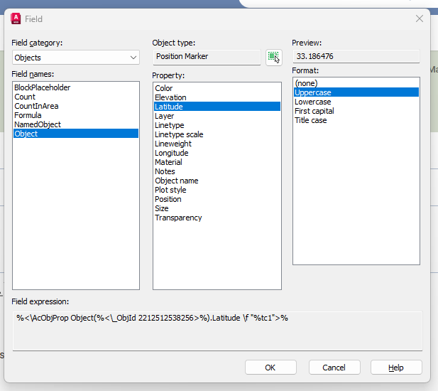
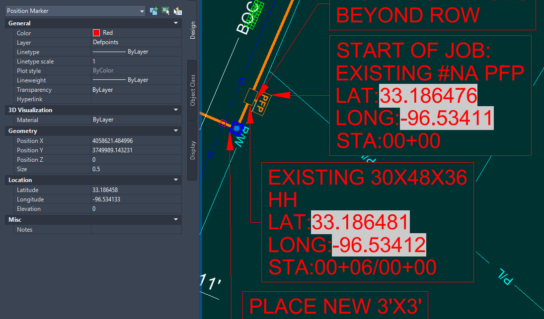
MLEADER WITH FIELDS FOR COORDINATES
SLW210 replied to SCHNIPPLES's topic in AutoCAD 2D Drafting, Object Properties & Interface
They are just FIELDS referencing a Position Marker as shown in the image of the Field Dialog Box you posted. They are just Multileaders with the fields added into the MText. This is just a good use of Multileaders, no need for any blocks.- 1 reply
-
- 1
-

-
Add to the code the ability to create layouts for non-standard formats
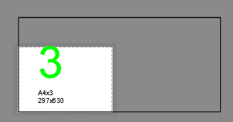
Nikon posted a topic in AutoLISP, Visual LISP & DCL
Hello everyone! There is a wonderful lisp AddLay.LSP. I've been using it for a few years now. It creates layouts standard A1, A2, and A3 formats... Can anyone add to this code the ability to create layouts for non-standard formats (A4x3, A4x4, A3x3, A3x4, A2x3, A2x4...). So far, no one has been able to implement this. I would be very grateful. The code creates viewports for non-standard formats, but the formats need to be set manually. The code works with polyline frames and dynamic frame blocks. In the file dwg shows that a viewport is being created for a non-standard format, but the format is not being set. List of non-standard formats: _A4x3_(297.00_x_630.00_MM) _A4x4_(297.00_x_841.00_MM) _A4x5_(297.00_x_1051.00_MM) _A3x3_(420.00_x_891.00_MM) _A3x4_(420.00_x_1189.00_MM) _A3x5_(420.00_x_1486.00_MM) _A2x3_(594.00_x_1261.00_MM) _A2x4_(594.00_x_1682.00_MM) _A2x5_(594.00_x_2102.00_MM) ;;; AddLayEn / Original AddLay Author: Andrey_13 / 08.2015 / ;;; Translation to English: 03.2025 ;;; Creation of Layouts and Viewports based on frames in Model Space (defun C:AL (/ ActiveDocument Application Display DeleteLayouts FirstSheet Flag Formats i j Layout Layouts Layer ModelSpace NumberFormats PaperSpace Points MatchSheet MinPoint MaxPoint NoMatchSheet Object Point1 Point2 Point1x Point1y Point2x Point2y Scale Square ViewportHeight ViewportWidth Viewport X Y ) (vl-load-com) ; Load ActiveX functions (setvar "CTAB" "Model") ; Switch to Model tab (initget 6) (setq Application (vlax-get-acad-object) ; Application object ActiveDocument (vla-get-ActiveDocument Application) ; Active document object ModelSpace (vla-get-ModelSpace ActiveDocument) ; Model space pointer Layouts (vla-get-Layouts ActiveDocument) ; Layouts collection Display (vla-get-Display (vla-get-Preferences Application)) ; Display preferences ) ;;; Prompt for the layer containing frames by selecting an object (while (null Object) (setq Object (car (entsel " Select an object to define the frames layer: "))) ) (setq Layer (cdr (assoc 8 (entget Object))) ; Determine layer name Formats (ssget (list (cons 8 Layer))) ; Select all objects on that layer NumberFormats (sslength Formats) ; Count number of frames Scale (getreal " Enter scale 1:<1>: ") ; Request scale i 0 Points () ) (if (not Scale) (setq Scale 1)) (repeat NumberFormats (setq Format (vlax-ename->vla-object (ssname Formats i))) (if (and (= (vla-get-ObjectName Format) "AcDbBlockReference") (= (vla-get-IsDynamicBlock Format) :vlax-true)) ; Check if dynamic block (progn (setq Points (append Points (list (GetBoundingBox_dynblock (vlax-vla-object->ename Format))))) ; Get points for dynamic block (setq i (1+ i)) ) (progn (vla-GetBoundingBox Format 'MinPoint 'MaxPoint) ; Get points for regular object (setq Points (append Points (list (list (vlax-safearray->list MinPoint) (vlax-safearray->list MaxPoint)))) i (1+ i) ) ) ) ) ;;; Determine sorting order for the points (setq i 0) (repeat (length Points) ; Build lists of X and Y coordinates (setq X (append X (list (caar (nth i Points))))) (setq Y (append Y (list (cadar (nth i Points))))) (setq i (1+ i)) ) (if (> (- (MaxElement X) (MinElement X)) (- (MaxElement Y) (MinElement Y))) ; Decide sorting axis (setq Points (vl-sort Points (function (lambda (P1 P2) (< (caar P1) (caar P2)))))) ; Sort by X (setq Points (vl-sort Points (function (lambda (P1 P2) (> (cadar P1) (cadar P2)))))) ; Sort by Y ) ;;; Disable automatic viewport creation on new layouts (if (= (vla-get-LayoutCreateViewport Display) :vlax-true) (progn (vla-put-LayoutCreateViewport Display :vlax-false) (setq Flag T) ) ) ;;; Layout management (initget 1 "Yes No") (setq DeleteLayouts (getkword " Delete existing layouts? [Yes/No]: ")) (cond ( (= DeleteLayouts "Yes") ;;; Delete all layouts except Model (vlax-for Layout Layouts (if (/= (vla-get-Name Layout) "Model") (vla-delete Layout) ) ) (initget 6) (setq FirstSheet (getint " Starting sheet number: ")) (vla-put-Name (vla-Item Layouts 1) (itoa FirstSheet)) ; Rename the default remaining layout ) ;;; Handle existing layouts if not deleting ( (= DeleteLayouts "No") (while (= NoMatchSheet nil) (progn (initget 6) (setq i 0 FirstSheet (getint " Starting sheet number: ") MatchSheet nil ) (repeat NumberFormats (if (not (null (member (itoa (+ FirstSheet i)) (layoutlist)))) (setq MatchSheet T) ) (setq i (1+ i)) ) (if (= MatchSheet T) (alert "Error: Layout names already exist!") (setq NoMatchSheet T) ) ) ) ) ) ;;; Insert new layouts and create viewports (setq i 0 j 0) (repeat NumberFormats (cond ;;; Workflow if layouts were deleted ( (= DeleteLayouts "Yes") (if (= i 0) (progn (setq Layout (vla-item Layouts 0)) (setvar "CTAB" (itoa FirstSheet)) ) (progn (setq Layout (vla-Add Layouts (itoa (+ FirstSheet i)))) (setvar "CTAB" (itoa (+ FirstSheet i))) ) ) ) ;;; Workflow if adding to existing layouts ( (= DeleteLayouts "No") (progn (setq Layout (vla-Add Layouts (itoa (+ FirstSheet i)))) (setvar "CTAB" (itoa (+ FirstSheet i))) ) ) ) ;;; Viewport creation logic (setq Point1 (car (nth j Points)) Point2 (cadr (nth j Points)) PaperSpace (vla-get-paperspace ActiveDocument) Point1x (car Point1) Point1y (cadr Point1) Point2x (car Point2) Point2y (cadr Point2) ViewportHeight (/ (abs (- Point1y Point2y)) Scale) ViewportWidth (/ (abs (- Point1x Point2x)) Scale) Viewport (vla-AddPViewport PaperSpace (vlax-3d-point (list (/ ViewportWidth 2) (/ ViewportHeight 2))) ViewportWidth ViewportHeight)) (vla-display Viewport :vlax-true) (vla-put-mspace ActiveDocument :vlax-true) ; Activate model space inside viewport (vla-zoomcenter Application (vlax-3d-point (list (/ (+ Point1x Point2x) 2) (/ (+ Point1y Point2y) 2))) 1.0) (vla-put-mspace ActiveDocument :vlax-false) ; Deactivate model space (vla-put-standardscale Viewport acVpCustomScale) (vla-put-CustomScale Viewport (/ 1.0 Scale)) (vla-put-DisplayLocked Viewport :vlax-true) ; Lock viewport ;;; Page Setup (vla-put-StyleSheet Layout "monochrome.ctb") (vla-put-PlotType Layout 5) ; Set plot area to "Layout" ;;; Determine Paper Size based on viewport area (Square) (setq Square (* ViewportHeight ViewportWidth)) (cond ((and (> Square 59251) (< Square 65488)) (vla-put-ConfigName Layout "DWG To PDF.pc3") (vla-put-CanonicalMediaName Layout "ISO_full_bleed_A4_(297.00_x_210.00_MM)")) ((and (> Square 118503) (< Square 130977)) (vla-put-ConfigName Layout "DWG To PDF.pc3") (vla-put-CanonicalMediaName Layout "ISO_full_bleed_A3_(420.00_x_297.00_MM)")) ((and (> Square 237006) (< Square 261954)) (vla-put-ConfigName Layout "DWG To PDF.pc3") (vla-put-CanonicalMediaName Layout "ISO_full_bleed_A2_(594.00_x_420.00_MM)")) ((and (> Square 474012) (< Square 523908)) (vla-put-ConfigName Layout "DWG To PDF.pc3") (vla-put-CanonicalMediaName Layout "ISO_full_bleed_A1_(841.00_x_594.00_MM)")) ((and (> Square 948024) (< Square 1047816)) (vla-put-ConfigName Layout "DWG To PDF.pc3") (vla-put-CanonicalMediaName Layout "ISO_full_bleed_A0_(841.00_x_1189.00_MM)")) (T (vla-put-ConfigName Layout "None")) ; Default to No plotter for non-standard sizes ) (if (> ViewportHeight ViewportWidth) (vla-put-PlotRotation Layout 1) (vla-put-PlotRotation Layout 0)) ; Orientation (command "_Zoom" "_All") (setq i (1+ i) j (1+ j)) ) ;;; Restore "Automatic Viewport Creation" setting if it was originally ON (if (= Flag T) (vla-put-LayoutCreateViewport Display :vlax-true)) (setvar "CTAB" "Model") ; Return to Model tab (princ " Creation of layouts completed.") (princ) ) ;;; Find minimum element in list (defun MinElement (X /) (car (vl-sort X '<))) ;;; Find maximum element in list (defun MaxElement (X /) (car (vl-sort X '>))) ;;; Get correct Bounding Box for Dynamic Blocks (defun GetBoundingBox_dynblock (ent / lst ins_pt min_point max_point 3d_polarp) (if (and (or ent (= (type (setq ent (vl-catch-all-apply (function (lambda () (car (entsel " Select Dynamic Block: "))))))) 'ename) ) (setq ent (vlax-ename->vla-object ent)) (vlax-property-available-p ent 'isdynamicblock) (equal (vla-get-isdynamicblock ent) :vlax-true) ) (progn (vlax-for item (vla-item (vla-get-blocks (vla-get-activedocument (vlax-get-acad-object))) (vla-get-name ent) ) (if (equal (vla-get-visible item) :vlax-true) (setq lst (cons item lst)) ) ) (setq ins_pt (vlax-safearray->list (vlax-variant-value (vla-get-insertionpoint ent))) lst (vl-remove nil (mapcar '(lambda (x / minp maxp) (if (not (vl-catch-all-error-p (vl-catch-all-apply (function (lambda () (vla-getboundingbox x 'minp 'maxp)))))) (list (cons "min" (vlax-safearray->list minp)) (cons "max" (vlax-safearray->list maxp))) ) ) lst ) ) lst (mapcar '(lambda (mins) (mapcar '(lambda (fun) (apply (read mins) (mapcar (function fun) (mapcar '(lambda (pts) (cdr (assoc mins pts))) lst) ) ) ) (list car cadr caddr) ) ) (list "min" "max") ) lst (mapcar '(lambda (ept) (mapcar '(lambda (coord_pt coord_line coord_ins) (+ (* coord_pt ((eval (read (strcat "vla-get-" coord_line "EffectiveScaleFactor"))) ent)) coord_ins) ) ept '("X" "Y" "Z") ins_pt ) ) lst ) ) ) ) ) AL.dwg
-
 Xi Schumann joined the community
 -

Hello everyone! Please take a look at this.
yangguoshe replied to sd2006's topic in AutoLISP, Visual LISP & DCL
try this (cons 1 (strcat (rtos (/ area 1000000.0) 2 2) "m\U+00B2")) -

[LISP] BPDF - Batch export Model Space title block frames to individual PDFs
BIGAL replied to Beastt1992's topic in AutoLISP, Visual LISP & DCL
I have a plot title blocks in model space version. I have say 5 different plot lisps depending on what say printer is involved color, B-W, A1 or A3 and so on. As in my last job in a multi storey building, you can get a users name and send the prints to the closest printer to them. -
[LISP] BPDF - Batch export Model Space title block frames to individual PDFs
Beastt1992 replied to Beastt1992's topic in AutoLISP, Visual LISP & DCL
Yes, I used Claude (AI) to help write and debug the code. I'm not an AutoLISP expert - I came up with the concept andrequirements, and used AI to help implement it. The logic, testing, and bug fixes were done through back-and-forth with the AI based on real errors I encountered in AutoCAD. -

[LISP] BPDF - Batch export Model Space title block frames to individual PDFs
CAD_Noob replied to Beastt1992's topic in AutoLISP, Visual LISP & DCL
hi. sorry to ask. Did you use Vibe coding on this? Coz I notice formatting similarities - Yesterday
-
[SHARE] SyncBlock - Synchronize specific layers across multiple blocks with precise alignment
Beastt1992 replied to Beastt1992's topic in AutoLISP, Visual LISP & DCL
Haha, mother-in-law nightmares are a universal architectural problem regardless of profession. Glad it gave you a chuckle either way -
 Riyan Dino joined the community
 -

[SHARE] SyncBlock - Synchronize specific layers across multiple blocks with precise alignment
rlx replied to Beastt1992's topic in AutoLISP, Visual LISP & DCL
I don't work with an architectural background so my nightmares are somewhat different than yours (most of them are about my mother in law or my sister in law) but thank you for sharing. High Lee , oh sorry , highly appreciated -
 luzcid joined the community
 -

Hello everyone! Please take a look at this.
mhupp replied to sd2006's topic in AutoLISP, Visual LISP & DCL
chr instead of string. (cons 1 (strcat (rtos (/ area 1000000.0) 2 2) "m" (chr 0178))) also might be the font your using. https://www.cadtutor.net/forum/topic/75383-text-ascii/#findComment-596226 -
[SHARE] SyncBlock - Synchronize specific layers across multiple blocks with precise alignment
Beastt1992 posted a topic in AutoLISP, Visual LISP & DCL
Hi everyone, I want to share a LISP tool I recently developed called SyncBlock. If you work with architectural or MEP backgrounds, you probably deal with this nightmare constantly: You have a Master Block (A), and several child blocks (B, C, D) that were copied from A but have some layers deleted to show different details. When the Master Block updates, synchronizing those child blocks without ruining their specific layer visibility—and without them flying off to random coordinates because their base points are all set to (0,0,0)—is a huge pain. To solve this, I wrote a script that does the following: 1. You select the Master Block. 2. You window-select the target blocks. 3. The script reads which layers are currently active in the target block, clears it, and pulls only those matching layers from the Master Block. The Magic (Consensus Voting Algorithm): The biggest challenge was alignment. Standard Bounding Box methods fail if you delete half a room or add a dimension in the child block. To fix this, the script uses a "Consensus Voting" approach. It gathers all valid geometry centers in both blocks, pairs them up, calculates the displacement vectors (dX, dY), and lets them "vote." The offset with the overwhelming majority wins. This ensures pixel-perfect alignment even if the child block is heavily trimmed! GitHub Repository: https://github.com/beastt1992/SyncBlock-AutoCAD The code avoids copying Hatches to prevent associativity crashes, and it safely handles older AutoCAD versions (like 2014) by using pure English prompts to avoid ANSI/UTF-8 encoding issues. I’d love for you guys to test it out on your messy real-world drawings! Any feedback, bug reports, or suggestions for improvement are highly appreciated. Cheers! -

MLEADER WITH FIELDS FOR COORDINATES
SCHNIPPLES posted a topic in AutoCAD 2D Drafting, Object Properties & Interface
Hello, We have an engineering vendor that submits drawings to us that have mleaders that contain fields correspond to lat and long, making labeling very quick when placing mleaders. Does anyone know this works? Are the mleaders a block? There is a position marker linked to the field with the Lat/Long but I can't imagine they are placing the fields manually each time this wouldn't be a time saver if so. I found a program called smart leader on autocad store, which seems to do this but I was just wondering if this can be achieved through blocks alternatively. Thanks EXAMPLE.dwg
-
Hello everyone! Please take a look at this.
SLW210 replied to sd2006's topic in AutoLISP, Visual LISP & DCL
Please use Code Tags for your code in the future. (press the <> in the editor toolbar) -
Could you please take a look and explain why this Lisp program is producing this result? 27807.35m² Please help me adjust the result. 27807.35m² I know nothing about Lisp. thank you . (defun rh:dxf (code lst) (cdr (assoc code lst))) (defun c:aa ( / cmde ent e_typ e_lst area vtx x_lst y_lst z_lst x_pt y_pt z_pt c_lst v_lst ss sum) (cond ( (/= 0 (getvar 'cmdecho)) (setq cmde (getvar 'cmdecho)) (setvar 'cmdecho 0) ) ) (while (setq ss (ssget "_+.:E:S" '((0 . "POLYLINE,LWPOLYLINE") (-4 . "<OR") (70 . 1) (70 . 3) (70 . 5) (-4 . "OR>") ) )) (setq ent (ssname ss 0) e_typ (rh:dxf 0 (setq e_lst (entget ent))) area (getpropertyvalue ent "area") v_lst nil ) (cond ( (= e_typ "POLYLINE") (setq ent (entnext ent) vtx (rh:dxf 10 (entget ent)) ) (if (< (length vtx) 3) (setq vtx (reverse (cons 0.0 (reverse vtx))))) (while (/= "SEQEND" (cdr (assoc 0 (entget ent)))) (setq v_lst (cons vtx v_lst) ent (entnext ent) vtx (rh:dxf 10 (entget ent)) ) (if (< (length vtx) 3) (setq vtx (reverse (cons 0.0 (reverse vtx))))) ) (setq x_pt (/ (apply '+ (mapcar '(lambda (x) (car x)) v_lst)) (length v_lst)) y_pt (/ (apply '+ (mapcar '(lambda (x) (cadr x)) v_lst)) (length v_lst)) ) (if (= (setq sum (apply '+ (mapcar '(lambda (x) (caddr x)) v_lst))) 0.0) (setq z_pt 0.0) (setq z_pt (/ sum (length v_lst))) ) ) ( (= e_typ "LWPOLYLINE") (setq z_pt (rh:dxf 38 e_lst)) (foreach pr e_lst (if (= (car pr) 10) (setq v_lst (cons (cdr pr) v_lst))) ) (setq x_pt (/ (apply '+ (mapcar '(lambda (x) (car x)) v_lst)) (length v_lst)) y_pt (/ (apply '+ (mapcar '(lambda (x) (cadr x)) v_lst)) (length v_lst)) ) ) ) (setq c_lst (list x_pt y_pt z_pt)) (entmakex (list (cons 0 "MTEXT") (cons 100 "AcDbEntity") (cons 100 "AcDbMText") (cons 10 c_lst) (cons 40 (getvar 'textsize)) (cons 71 5) (cons 72 5) (cons 1 (strcat (rtos (/ area 1000000.0) 2 2) "m²")) ; (cons 1 (rtos (/ area 1000000.0) 2 3)) ; If you don't need the suffix "m²" ) ) ) (if cmde (setvar 'cmdecho cmde)) )