All Activity
- Yesterday
-

Multiple polyline viewport from model to layout
BIGAL replied to iztok14's topic in AutoLISP, Visual LISP & DCL
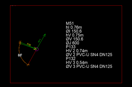
This is very much proof of concept, and needs some extra work but you can try it. I just did 162 layouts by selection did not try all 300+. You must use this new dwg as it has Layout1 set up correctly. I removed layout2 not needed. Obvious bug is if rectangs are not made in correct label sequence but can fix that if it happens. It uses creation order at moment. You should use 1 size for all the rectangs. ; https://www.cadtutor.net/forum/topic/98809-multiple-polyline-viewport-from-model-to-layout/ ; rectangs to layouts by AlanH ; Nov 2025 (defun rec2lays ( / ss ent txt ins pt2 pts ent2 co-ord mp ) (setvar 'ctab "Model") (setq ss (ssget (list (cons 0 "*TEXT") (cons 8 "SHEMA_NAME")(cons 410 "Model")))) (repeat (setq x (sslength ss)) (setq ent (entget (ssname ss (setq x (1- x))))) (setq txt (cdr (assoc 1 ent))) (setq ins (cdr (assoc 10 ent))) (setq pt2 (polar ins 5.4977 2.5)) (setq pts (list ins pt2)) (setq ent2 (ssname (ssget "F" pts (list (cons 0 "LWPOLYLINE")(cons 8 "SHEMA_RECT"))) 0)) (setq co-ord (mapcar 'cdr (vl-remove-if-not '(lambda (x) (= (car x) 10)) (entget ent2)))) (setq mp (mapcar '* (mapcar '+ (car co-ord) (caddr co-ord)) '(0.5 0.5))) (command "layout" "C" "Layout1" txt) (setvar 'ctab txt) (command "Mspace") (command "zoom" "c" mp 10) (command "zoom" "15XP") ; a custom scale of 15 seems to suit (command "Pspace") (setvar 'ctab "Model") ) (princ) ) sheme_JAS.dwg
-

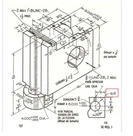
i need help in this piece, i need to Create the necessary views. Dimension the part and distribute the dimensions across the drawn views, Create a section cut in the indicated area so you don't have to dimension this radius as a hidden line (use whiche
ReMark replied to Manuel Marroquín's topic in Student Project Questions
So... what you need to create is a top, front and side view as well as a sectional view in 2D. Have you done anything like that in the past? -
Multiple polyline viewport from model to layout
BIGAL replied to iztok14's topic in AutoLISP, Visual LISP & DCL
As suggested can be done you would look for the "Mx" value then find the co-ords of the rectang, make a layout and create a viewport. You need to provide a couple of things, it would be best to have 1 true size title block in say "Layout1" this would be copied repeatedly. If you dont use a title block ignore. Part 2 as already requested you need to set one size for the layouts. Say a A4 etc. The rectangs are different sizes you need to set the size to match the biggest rectang say M15 as example then a proper scale can be used for the viewport. The layouts are then consistent. So get something like this at a fixed scale.
-
Thanks, though it can be improved a bit too - I reckon the point of intersections would be better off on the lines between height points - tried that just now but got myhead going round in circles with a part of it. Will see what I can do for later
-
@Steven P that works way better than i dreamed... even if you say its a bit dirty... Being able to select the intersection of datum and reference line, and the scaling option is brilliant.. If i had a box of Jaffa Cakes they would be in your hands right now.... Thank you soo much.... @BIGAL thank you for the reply and i think i understand what you mean... but i need to leave some work for my understudy to do can't speed him up too much.....
-
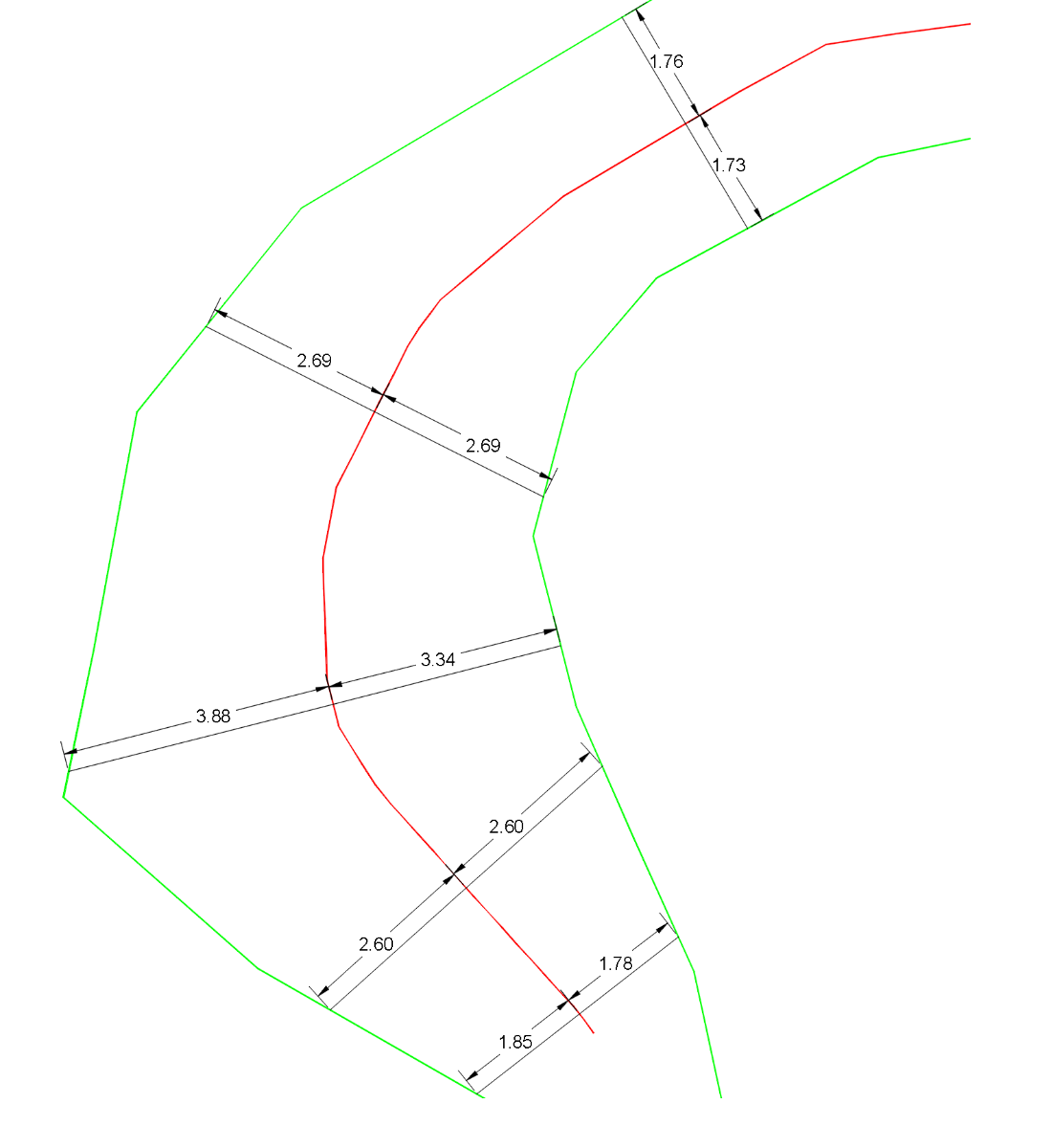
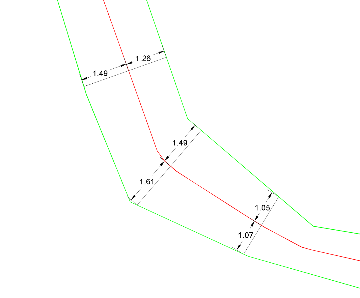
Yes. My "one/cross-eyed" son has quite a few limitations: he only sees reality from one point of view. But reality is best analyzed in "Stereo." For the same reason, I think we need to analyze both polylines in the same way and at the same time (using angle bisectors). I hope to have time to make progress on my "good approach" next weekend. Someone has "travelled very far" in experimenting with this type of calculation: @marko_ribar I think it would be very interesting to hear his opinion on this.
-

Multiple polyline viewport from model to layout
Saxlle replied to iztok14's topic in AutoLISP, Visual LISP & DCL
Do you have a desired layout format (paper size), desired scale, etc. or you just want to display of each viewport from model space no matter the scale, paper size, etc.? -

Multiple polyline viewport from model to layout
iztok14 replied to iztok14's topic in AutoLISP, Visual LISP & DCL
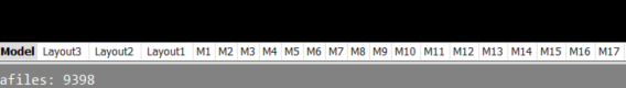
Thank s for answer. Here is my case . In this drawing need to create 355 viewports in ONE layout paperspace. The rectangul of viewport is on layer "SHEMA_RECT". sheme_JAS.dwg -
 Timbo joined the community
 -
 sun.ni2655 joined the community
 -
 PeterB100 joined the community
 -
 park joined the community
 -
 temp123user joined the community
 -
 rawhmansyah joined the community
 - Last week
-
As I have said many times I use POP menus for block libraries, you can select internal or external blocks for insertion. Pop menus should be fine in LT even earlier versions.
-
Multiple polyline viewport from model to layout
BIGAL replied to iztok14's topic in AutoLISP, Visual LISP & DCL
Yes like many others as suggetsed @aridzv I have something, and have made like 50+ in one go. You need to post a sample dwg to see how you are attempting to do this. -
If you break down the top surface and convert it into a single Pline, Then you can label every point into a cross section shape. You would need to say set the RL of the 1st point enter Hor and Ver scales if applicable. Draw a datum line then can put text below it. There is 2 levels at some points but that can be taken into account. So maybe post a few cleaned up version of the SINGLE plines.
-
I have just created a load of blocks for future use, they where in the block panel, but have now disappeared? is thewre a tutorial for creating a block library. Using 2026LT
-

Multiple polyline viewport from model to layout
aridzv replied to iztok14's topic in AutoLISP, Visual LISP & DCL
have a look on this topic; -
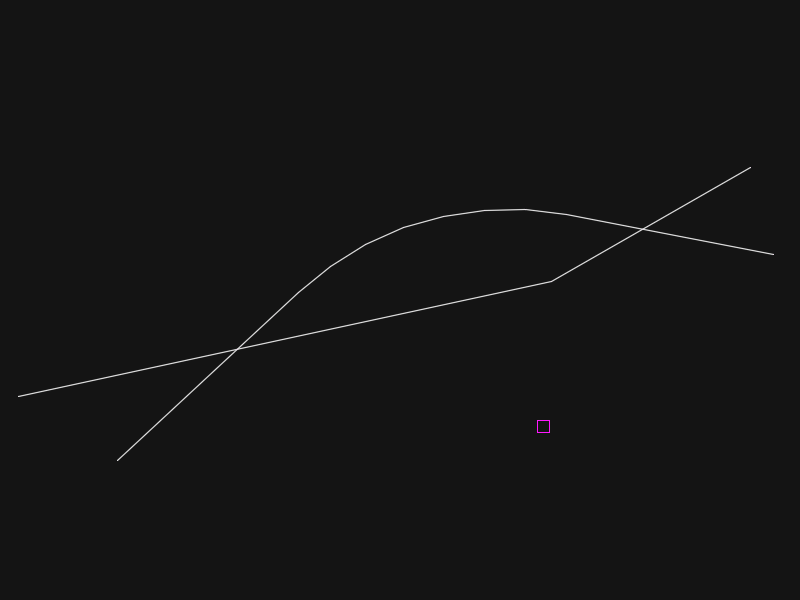
I think this is something that Civil3D covers - BigAl knows these things better than me though. This is a very quick and dirty LISP: Noting that your lines are 1000x longer than the reference texts, I have a multiplier (hit enter to just accept the 1000, you can change the code to suit) Select the reference polyline - I am assuming always a horizontal reference line as your example Select the point that the height texts refer to (is it the centre of the '+', in the drawing there is a point drawn at the correct height next to each text) and then the associated text. Repeat along the points Exit badly with the escape key. I am going to get abuse for cutting corners there... Slight difference to your example that my lines are drawn from the closest point on the polyline that you selected (defun c:test ( / Multiplier ReferencePoly ReferenceY EndLoop MyPoint MyHeight MyHt ClosestPoint) (defun MkLn ( pt1 pt2 Layer / Ln ) ;; Add in layer etc details (setq Ln (entmakex (list '(0 . "LINE") '(100 . "AcDbEntity") '(410 . "Model") '(62 . 0) '(100 . "AcDbLine") (cons 8 Layer) (cons 6 "CONTINUOUS") (cons 62 256) (cons 10 pt1) (cons 11 pt2) '(210 0.0 0.0 1.0) ))) ; end list, entmakex, setq ) (setq Multiplier (getreal "Enter Height Multiplier (1000)")) (if (or (= Multiplier nil)(= Multiplier "")(= Multiplier 0)) (setq Multiplier 1000) ) (setq ReferencePoly (car (entsel "Select Reference Polyline"))) (setq ReferenceY (cdr (assoc 10 (entget ReferencePoly)))) (setq EndLoop "No") (while (= EndLoop "No") (setq MyPoint (getpoint "Select Point")) (setq MyHeight (car (entsel "Select Height text"))) (setq MyHt (cdr (assoc 1 (entget MyHeight)))) (setq ClosestPoint (vlax-curve-getclosestpointto ReferencePoly MyPoint)) (MkLn ClosestPoint (mapcar '* '(1 1 0) (mapcar '+ (list 0 (* Multiplier (atof MyHt)) 0) ClosestPoint)) "0") ) )
-

What’s New in AutoCAD 2026.1.1: Experience the Connected Sheet Set Manager and Enhanced Smart Blocks
The AutoCAD Blog posted a topic in AutoCAD Blogs
We are excited to announce the release of AutoCAD 2026.1.1, which includes important enhancements that will significantly elevate your design, drafting and collaborative workflows. This update, which can be installed via the Autodesk Access application, focuses on improving the Sheet Set Manager feature and making Smart Blocks fully functional. Dive into the details below! Enhanced Functionality With the Connected Sheet Set Manager The Sheet Set Manager receives a substantial upgrade in AutoCAD 2026.1.1. Here’s what’s new: Cloud Sheet Sets: The Connected Sheet Set Manager now fully supports working with, and organizing, cloud sheet sets. This update enhances performance when loading and handling these sheet sets, making your workflows smoother and saving you time. Real-Time Collaboration: Clear indicators for the status of your sheet sets are now visible, informing you of concurrent edits by other collaborators and providing you with real-time notifications of data conflicts. This feature ensures that you’re always aware of changes being made, allowing for better collaboration with your team. Removal of Sheet Set Manager for Web: Please note that the Sheet Set Manager for Web has been removed starting with this release of AutoCAD 2026.1.1. This change aims to streamline processes and focus on enhancing the desktop experience. The Connected Sheet Set Manager delivers the same concurrent editing experience as it did on the Web, but also ensures consistent workflows for more experienced users, whether they are working in Autodesk Docs or locally. Important Notice: Working with sheet sets between AutoCAD 2026.1.1 and Autodesk Civil 3D 2026 or 2026.1 may result in compatibility issues. For an enhanced and fully supported workflow we recommend waiting for the next Autodesk Civil 3D 2026 update. Smart Blocks: Detect and Convert Fully Implemented We are thrilled to announce that the detection capability and functionality of Smart Blocks are now fully implemented and no longer in Tech Preview. Initially introduced in AutoCAD 2026, Smart Blocks: Detect and Convert scans your entire drawing using the power of Autodesk AI, and then makes intelligent inferences to determine all the instances that you may want to convert into blocks. Detecting these potential blocks all at once is especially helpful in situations when extensive cleanup is required or when geometry may vary slightly, such as for imported drawings. AutoCAD 2026.1.1 brings significant improvements to your design experience, making sheet set management more fluid and Smart Blocks functionality more robust. These enhancements reinforce our commitment to providing you with the tools you need for a successful and efficient design workflow. Update to AutoCAD 2026.1.1 today If you already started your update at the beginning of this post, you should be one step closer to experiencing these features first-hand—if not, go ahead and go to the Autodesk Access application on your desktop. And if you’re not yet a subscriber, be sure to check out a free trial of AutoCAD 2026.1.1 Learn More To explore these features and enhancements in detail along with more additional updates included in the 2026.1.1 update, take a look at the following page in the Help section: What’s New in AutoCAD 2026.1.1 The post What’s New in AutoCAD 2026.1.1: Experience the Connected Sheet Set Manager and Enhanced Smart Blocks appeared first on AutoCAD Blog. View the full article -
 aziz joined the community
 -
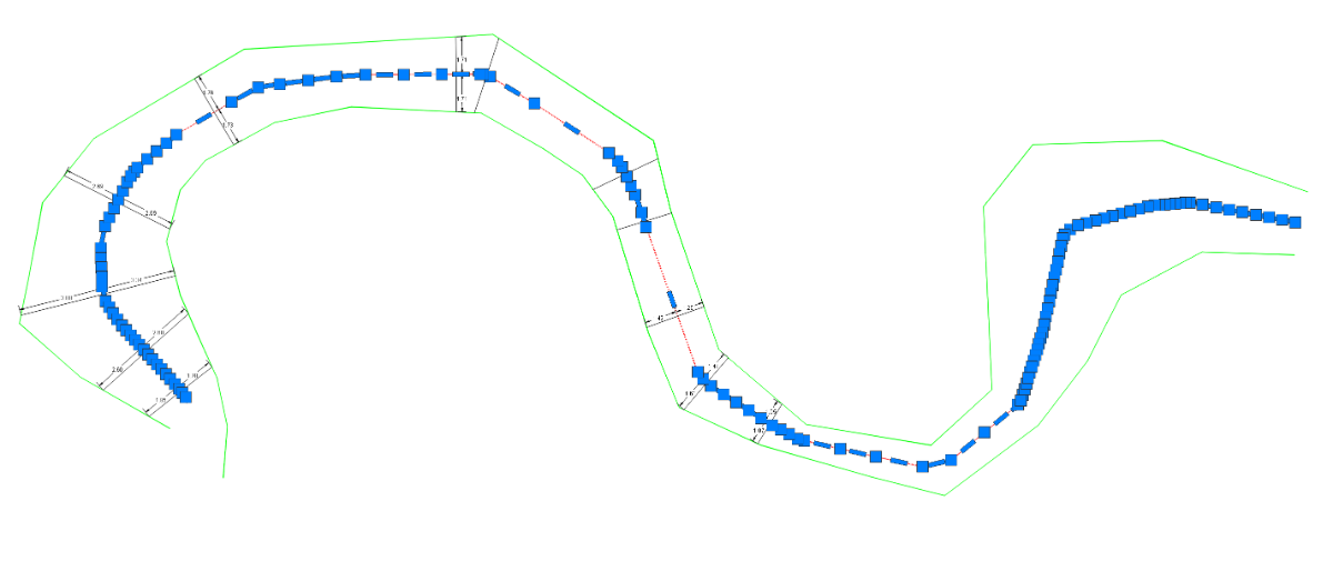
I fixed some of the errors, could you try again @PGia ? I see your point, it would be good to add the exact points on the corners to the estimated points from the rest of the function. Combine them into one polyline for a better result. I'll give it a try later when I have some time.
-
Being lazy as i am, and having done this a bazillion times, my brain says why not ask those that know if it is possible... So, we generate cross sections from very dodgy architects/landscape/civil engineers/ blokes called Bob etc drawings sent in for quotes... Quality of drawings we are sent can range from beer mat to Picasso.... Now then, we arrange the dodgy levels along the datum line, draw short polylines and stretch north wards by given a level, then join together to form a ground profile. My question is... would it be possible to create a lisp that we can use were we select a polyline along the datum line and then select the text adjacent and it would extend the polyline north of the datum line by the text amount ?? Polylinelisp.dwg
-

i need help in this piece, i need to Create the necessary views. Dimension the part and distribute the dimensions across the drawn views, Create a section cut in the indicated area so you don't have to dimension this radius as a hidden line (use whiche
Manuel Marroquín posted a topic in Student Project Questions
-
I’ve also tested @mhupp’s code. It gets fairly close to the centerline, but some strange errors appear. I think relying solely on finding the correct axis vertices probably means you can’t immediately compensate for an inaccurate result. That’s the downside of both Mhupp’s and GLAVCVS’s codes (his “one-eyed” version also produces odd results at times). SLW210’s approach might offer both options, but its outcome isn’t any better either. I suppose a method based on calculating many points helps to average out those errors, but the result can only be an approximation. And IMO, the result shouldn’t be an approximation — it should be exact.
-
@dexus I tested your first code. It's quite close to what the centerline should be, although at the inflection points it always works by approximation. It seems the goal is to obtain many points along the line to always be close to the correct axis, but: why not obtain the correct axis from the first point? In my opinion, it should be possible to obtain only the inflection points that will become segments equidistant from the reference polylines. Furthermore, in the middle of these inflection points there shouldn't be any more unnecessary points, but rather a single segment. As for your last code, I couldn't get it to run because some kind of error occurs.
-
 tranbao joined the community
 -
 Kevin Martin changed their profile photo
 -
Kevin Martin joined the community
-
 malayum mayra joined the community
 -

Cad nesting (auto nesting of multiple parts to optimize sheet space)
ahmet yurudu replied to Shib Sankar's topic in AutoLISP, Visual LISP & DCL
bunlar var ama 21 yetersiz 41 de baska sorunlar var NEST21.lsp NEST41.lsp -
Cad nesting (auto nesting of multiple parts to optimize sheet space)
ahmet yurudu replied to Shib Sankar's topic in AutoLISP, Visual LISP & DCL
selam yerleşim için lisp örneği buldun mu -
I made some changes so it also works when the starting lines are intersecting. Cool to see lots of people try to solve this problem! Mine doesn't work well with parallel lines and doesn't generate arcs. It still looks like GP_'s solution has the best result for me, but for intersecting lines I have to execute the function twice and select the lines in two directions to get the full result. centerline.lsp
-
Multiple polyline viewport from model to layout
iztok14 posted a topic in AutoLISP, Visual LISP & DCL
Hi, Im new here. I was wondering if exist any lisp routine to create multiple viewport from model space to layout at once. I have 190 polyline object "rectangular" in modelspace and i want to create viewports in paprespace at one time with the same scale besides each other? Thx ... Iztok -
With my code it wouldn't matter because they would reorder on how they fall on the temp polyline unless one poly line is really squiggly (technical term)