All Activity
- Today
-
My 5 cent (defun c:LLD () (c:LayerLegend)) (defun c:LayerLegend ( / df i l ln p1 pt sp DSC ENT NM ) ;; Lee Mac 2011 (vl-load-com) (if (and (setq pt (getpoint "\nSpecify Point for Legend: ")) (setq ln (* 100 (getvar 'TEXTSIZE))) ;(getdist "\nSpecify Length of Lines: " pt)) (setq pt (trans pt 1 0)) (setq i -1) (setq sp (* 2.5 (getvar 'TEXTSIZE))) ) (while (setq df (tblnext "LAYER" (null df))) (if (/= 16 (logand 16 (cdr (assoc 70 df)))) (setq l (cons (cdr (assoc 2 df)) l)) ) (setq l (acad_strlsort l)) )) (foreach n l (setq ent (vlax-ename->vla-object (tblobjname "LAYER" n))) (setq dsc (vlax-get-property ent 'Description)) (setq nm (vlax-get-property ent 'name)) (setq lc (itoa (vla-get-color ent ))) (entmakex (list (cons 0 "LINE") (cons 8 n) (cons 6 "ByLayer") (cons 62 256) (cons 10 (setq p1 (polar pt (* 1.5 pi) (* (setq i (1+ i)) sp))) ) (cons 11 (polar p1 0. ln)) (cons 370 -1) ) ) (entmakex (list (cons 0 "TEXT") ;*** (cons 1 (strcat n " : " lc " : " dsc)) ;* (the string itself) (cons 6 "BYLAYER") ; Linetype name (cons 7 (getvar 'TEXTSTYLE)) ;* Text style name, defaults to STANDARD, not current (cons 8 n) ; layer (cons 10 p1) ;* First alignment point (in OCS) (cons 11 p1) ;* Second alignment point (in OCS) (cons 39 0.0) ; Thickness (optional; default = 0) (cons 40 (getvar 'TEXTSIZE)) ;* Text height (cons 41 1.0) ; Relative X scale factor, Width Factor, defaults to 1.0 (cons 62 256) ; color (cons 71 0) ; Text generation flags (cons 72 0) ; Horizontal text justification type (cons 73 1) ; Vertical text justification type (cons 210 (list 0.0 0.0 1.0)) (cons 370 -1) ))) (princ) )
-
 james02 joined the community
 -

Need a tool for creating 2d outlines for complex 2d drawings
Ankit Pandit replied to Ankit Pandit's topic in AutoLISP, Visual LISP & DCL
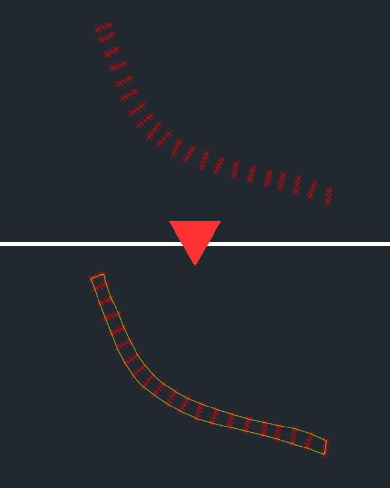
Ah got it — thanks for clarifying that, I wasn’t aware the Architecture toolset was included. That makes sense. I also had a chance to try the shrinkwrap command on a different setup (a friend using Civil), and saw similar behavior in the more detailed regions. From the result you shared, it does get quite close, but I’m still seeing some irregularities around the boundary in those complex areas, especially in some of my other projects. That’s been the tricky part in my case — getting a consistently clean outer boundary across the full shape. I’ve been testing EGBoundary across different setups — it’s been working consistently for me in AutoCAD and BricsCAD so far. I haven’t personally tried it yet in GstarCAD or ZWCAD, though I’ve seen them mentioned as compatible with GstarCAD and ZWCAD on their official website. Really appreciate you taking the time to test and share that. Thank you !! -
@mhupp Layer Filters the "Architect" shows "layers 1 & Layer 2" only. Sorry don't have code, but a google revealed in one post of so many suggestions.
- Yesterday
-

place align block through lisp going wrong
BIGAL replied to pmadhwal7's topic in AutoLISP, Visual LISP & DCL
Firstly your block is 9.4 long so, at a scale of 12 its 12x9.4 in length. So 1st step is scale down the block by 0.1 and resave then it is basically 1 unit long so a scale of 12 will be a fraction under a true 12 length. The other question is then what sclae factor to use for the Y value but this can be calculated as a factor of the scale and block height Y so they are all the same height. If you want it to be a true 1 unit can rescale to match that and save block. Hint 1.05843568371114 I don't have a problem working out the length or the insertion point. Those values are in your Excel example. You just need to work out the chainage of the start end of the pline. For me I would just start brand new code easier, will see what I can do and will read the Excel direct. -
Still don't know what your talking wanting. you can only select things on the layers. this will make a selection set of whats on those layers and on current tab. (setq ss (ssget "X" (list (cons 410 (getvar "CTAB")) (cons 8 "Layer[12]")))) (sssetfirst nil ss)
-

place align block through lisp going wrong
pmadhwal7 replied to pmadhwal7's topic in AutoLISP, Visual LISP & DCL
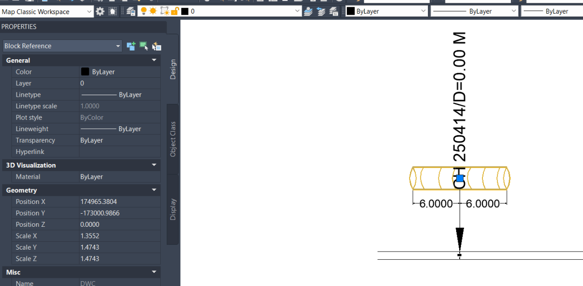
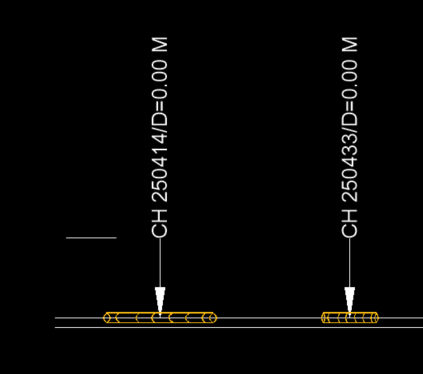
@BIGAL actually this is the chainage which means if we 250.408-250.420=12meter so my dwc pipe length is 12m at this point what i do i was calculate mid difference of those chainage and i was place mid chiange in autocad (as seen my dwg u can check)now i run the lisp which place those block like the align command it work so in taht portion dwc length should be 12 meters 6meters from each side of that 250414 but the isse is block length comming 8m instead of 12soemwhere the differnce is 2m somewhere 4 as the y scale is only for width so thats the not issue because i will change it by selecting all one time also i am not able to uderstand what u mean for 'scaled like 10 x timee' is anything wrong in my block?
-
place align block through lisp going wrong
BIGAL replied to pmadhwal7's topic in AutoLISP, Visual LISP & DCL
The DWC block has a insertion point at mid point, Still not sure about the wrong length and 4m dist. Can you also provide a dwg with before and after so can see how say first 3 blocks should look. add the excel data as MTEXT etc. Yes can read the Excel direct no need for a CSV. Ok understand in Excel from 250.408 to 250.420 so point is (250.408+250.420)/ 2.0 where label is. So need to establish start chainage of pline 250414 compared to start distance away and get that start point X&Y. Your DWC block appears to be scaled like 10 x times. Why is it not 1 unit long say actual is 0.9447 that fits in 1 unit. The scale for 12 would be just that. Also what is Y scale ? Does the block have a fixed height, Y ? Again edit block 1st. Then can do some code to match.
-
 Peter Vu joined the community
 - Last week
-
 a.ll.a.a joined the community
 -
 jamgriff joined the community
 -
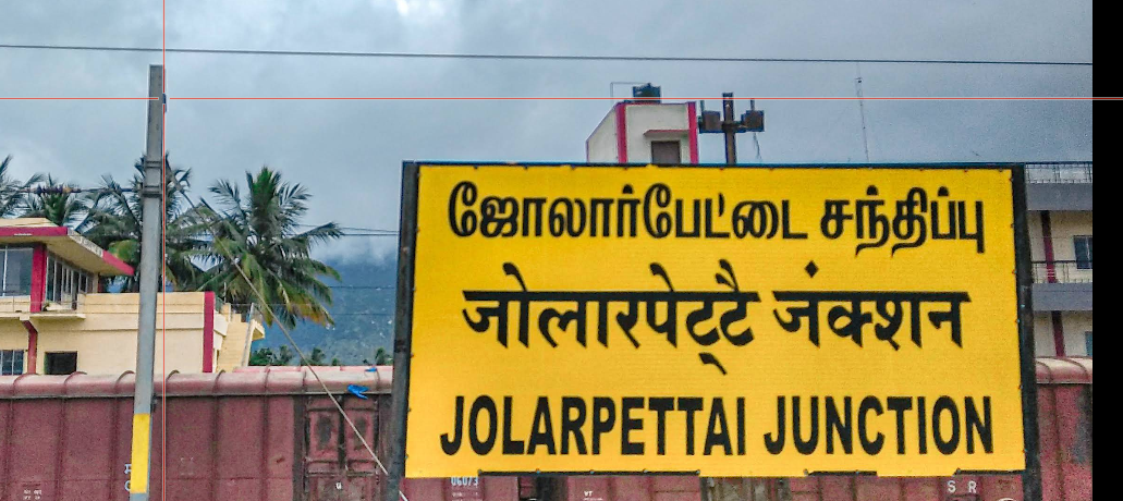
Not sure for ZWCAD, but it Tamil font installed on your computer, you should be able to access it if it is
-
in autocad i need to place block which was align in x scale i have lisp code too but the isseu is the block is placing wrongly i was place mid chainage of the point where i need to place those block but always it placing wrongly l;ike first length of my block is 12m but the code placing 8m 4 m each side i was attached all the input i have can anyone fix this Drawing2.dwg block.dwg PIPE_PlotBlocksFromCSV.lsp PIPE_Block.csv.xls.csv Book1.xlsx
-
@mhuppIt's like this For example , I have layer 1, layer 2 , layer 3 And I want to select layers 1 and 2, add them to the newgroup filter, and name it something like "architect".
-
 dffdfd joined the community
 -
I NEED TO TYPE TAMIL FONT HOW TO DO IN ZWCAD
-
 c31 joined the community
 -
 jmorris joined the community
 -
 yousef-M joined the community
 -
 saadahla527 joined the community
 -
 Rhold joined the community
 -

Need a tool for creating 2d outlines for complex 2d drawings
SLW210 replied to Ankit Pandit's topic in AutoLISP, Visual LISP & DCL
As I mentioned already, AutoCAD Architecture is FREE with the Toolset. All you need to do is download it. Architecture Toolset in Autodesk AutoCAD | Features This looks like something Bricscad should incorporate as well. That's the reason I stopped working on the LISP, but I will probably try to get it finished up anyway. -
Need a tool for creating 2d outlines for complex 2d drawings
Ankit Pandit replied to Ankit Pandit's topic in AutoLISP, Visual LISP & DCL
Thanks for sharing that and testing it. I’m currently using AutoCAD 2026 (standard), and from what I can see, the AECLINEWORKSHRINKWRAP functionality isn’t available in this version. It looks like it’s part of the Architecture/Civil toolsets, so accessing it would mean moving to something like Civil 3D or the AEC Collection, which is quite a big upgrade just to use this specific functionality. Really appreciate you taking the time to test it though. -
Need a tool for creating 2d outlines for complex 2d drawings
Ankit Pandit replied to Ankit Pandit's topic in AutoLISP, Visual LISP & DCL
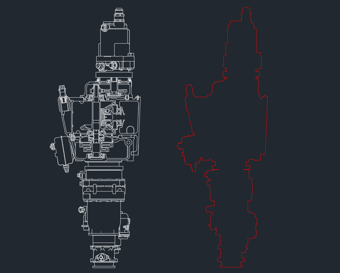
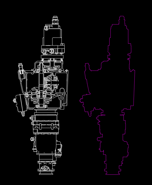
Thanks for pointing that out — I gave it a try on the same drawing. It actually handled the case surprisingly well and produced a clean outer boundary for the full shape, even with the gaps and more complex areas where the other approaches were struggling. Sharing the result here.
-
AutoCAD suitable laptop for a Mechanical Engineering freshman
BIGAL replied to BenG54's topic in Hardware & Operating Systems
Like @SLW210 I think you would be better off with a Windows Intel PC. Other CAD software that has MAC software is often reported as having niggly problems. Until there is a true MAC OS based say Autocad those problems may continue, in saying that there are some true MAC CAD programs out there. Autocad MAC has existed for like 30 years and still no true native version. -
Need a tool for creating 2d outlines for complex 2d drawings
SLW210 replied to Ankit Pandit's topic in AutoLISP, Visual LISP & DCL
Here is the result of the AECLINEWORKSHRINKWRAP in Archtecture. Engine Part Assembly_ArchSWrap.dwg
-

Creating a boundary to a group of points
todo terreno cad replied to Tyke's topic in AutoCAD General
"Doing this manually for 2 hours is insane for production workflows. I developed an AutoLISP solution that automates this. It bypasses the convex hull limitation and extracts the true concave perimeter from COGO points in 1 second. It's packaged in the Todo Terreno CAD Suite on the Autodesk App Store (first month is free). Command is TTC_POLY-PERIMETER. Optimize your time!"
-
Are you talking about layer states?
-
I really need a LISP program to select layers into Layer Filters and name this filter group. Please help me. Thank you!
-

Need a tool for creating 2d outlines for complex 2d drawings
Dahzee replied to Ankit Pandit's topic in AutoLISP, Visual LISP & DCL
@SLW210 Here you go. https://forum.bricsys.com/discussion/40003/extract-outer-boundary-of-2d-drawing#latest -
Need a tool for creating 2d outlines for complex 2d drawings
SLW210 replied to Ankit Pandit's topic in AutoLISP, Visual LISP & DCL
You have to purchase Civil 3D, Architecture is free with AutoCAD. OP still hasn't stated what CAD they are using. -
Need a tool for creating 2d outlines for complex 2d drawings
SLW210 replied to Ankit Pandit's topic in AutoLISP, Visual LISP & DCL
$119 USD, you get 15 day free trial. Most examples didn't show gaps, but looks like the user guide claims Auto Tolerance and Auto island detection. Could you link the discussion on Bricscad for the OP? -
AutoCAD suitable laptop for a Mechanical Engineering freshman
SLW210 replied to BenG54's topic in Hardware & Operating Systems
AutoCAD for Windows has more features than AutoCAD for Mac. Compare Features: AutoCAD for Windows against AutoCAD for Mac -
Need a tool for creating 2d outlines for complex 2d drawings
Dahzee replied to Ankit Pandit's topic in AutoLISP, Visual LISP & DCL
I think this is the product BIGAL was referring to.https://engenext.com/pages/egboundary.html I have no affiliation to this product, I just remember seeing it discussed on the Bricscad forum. -
Need a tool for creating 2d outlines for complex 2d drawings
Ankit Pandit replied to Ankit Pandit's topic in AutoLISP, Visual LISP & DCL
Thanks for all the suggestions, really appreciate you taking the time to look into this. I tried a few of the approaches mentioned — they seem to work quite well on cleaner geometry, but in cases like mine with small gaps and more complex connections, I’m still seeing partial or inconsistent boundaries being generated. I’ve attached a simplified sample from one of my project drawings. This represents the kind of geometry I’m dealing with, where standard methods haven’t been giving consistent results. Curious to see how your approaches handle this case. Engine Part Assembly.dwg