All Activity
- Today
-

Change plotstyles display on all currently open docs?
mhupp replied to 3dwannab's topic in AutoLISP, Visual LISP & DCL
AutoCAD doesn't like multiple drawings. you will either have to do scripts or maybe vl-propagate ? -

Get length of MLeader/QLeader spline.
Isaac26a replied to SLW210's topic in AutoLISP, Visual LISP & DCL
I think the translation to 1958's lisp is this, although not quite sure is the best ;;; Multi-length ;;; https://www.cadtutor.net/forum/profile/26931-1958/ ;;; 28 august 2025 (defun c:ml (/ ent pline txt p1 p2) (vl-load-com) (while (setq pline (vlax-ename->vla-object (car (setq ent (entsel "\n indicate the line \n"))))) (setq txt (strcat "L = " (rtos (vlax-curve-getDistAtParam pline (vlax-curve-getEndParam pline)) 2 2) " m" ) ) (setq p1 (vlax-curve-getClosestPointTo pline (cadr ent)) p2 (getpoint p1 "\n insertion point >> \n") ) (vl-cmdf "_mleader" p1 p2 txt) (setq ent (vlax-ename->vla-object (entlast))) (vla-put-TextHeight ent 2.00) ; font size (height) (vla-put-TextJustify ent 1) ; text alignment (1-left) (vla-put-TextLeftAttachmentType ent 4) ; append text to left (vla-put-TextRightAttachmentType ent 4) ; append text to the right ;;; 0 - top of line 1 ;;; 1 - middle of line 1 ;;; 2 - bottom of line 1 ;;; 3 - underline of line 1 ;;; 4 - middle of text ;;; 5 - middle of last line ;;; 6 - bottom of last line ;;; 7 - underline of last line ;;; 8 - underline of all text (vla-put-DoglegLength ent 0.5) ; shelf size (length) ;;; (vla-put-TextStyleName ent "ext til") ; change text style ) (princ) ) ;|?Visual LISP Format Options? (100 1 2 2 nil " " 80 60 0 0 0 nil nil nil T) ;*** Please add text under the comments! ***|; -

Change plotstyles display on all currently open docs?
Steven P replied to 3dwannab's topic in AutoLISP, Visual LISP & DCL
So where is it going wrong? Is it switching between drawings or just switching to one drawing and then stopping? -

Tackling A New Workshop Build With AutoCAD Web: Part 2
The AutoCAD Blog posted a topic in AutoCAD Blogs
AutoCAD Web is a fantastic collaboration tool when used on an AutoCAD project. The project can be large or small—it really doesn’t matter. The time-saving workflows that AutoCAD Web provides can facilitate seamless collaboration between office and site, making your DWG files completely mobile. In my previous article about my workshop build, I went through how the AutoCAD mobile application (part of AutoCAD Web) on an iPad Pro helped me dramatically with the workshop build. In this second of three articles, I will explain more in-depth how I have utilized AutoCAD Web by collaborating with myself. That may sound incredibly strange, but this AutoCAD collaboration technology can save a tremendous amount of time by making your drawings mobile and providing real-time edits to your drawings when out in the field or, in my case, in an old outbuilding on the land adjoining my house. To briefly recap, those of you who follow my social media (Not Just CAD) may have noticed that I was (and still am) working on a new workshop/office build. I am building a small, timber-framed building within an older, timber-framed outbuilding on our property in East Yorkshire in the UK. While it was only a small project, I applied AutoCAD technology to create simple, annotated drawings for ease of use. It was much easier than scribbling paper notes, sketches, and random notes on my iPad, where references to those notes often got forgotten. Now, let’s take a look at how my simple AutoCAD drawings allowed me to start estimating materials and develop more views of the new workshop/office build. Drawing Development In part one of the series, I talked about the initial site survey and how I drew up existing details to get an idea of how I wanted the workshop/office to look and also how I wanted the office to be placed. This was a building within a building, after all. The drawings now needed development as the project progressed. I needed to start looking at the materials I was going to use: flooring, walls, insulation, and even a window, even though the new office part of the workshop was inside! (I’ll explain that one a bit later in the blog). To do this, I was going to use simple polylines drawn over plans and elevations that I had already created. The actual real-world measurements were in place already, and I just needed to overlay those polylines to get an idea of material quantities and costs. A Solid Foundation The existing workshop already had a reinforced concrete floor, so all I needed was to build a timber floor grid over a damp-proof membrane (DPM), insert insulation, and then add interlocking timber floor panels. Using a simple polyline outline for each floor panel (and part panel), combined with hatching, I easily created a floor panel layout (see Figure 1) that highlighted exactly how many panels and part panels were needed. I used the interior outline of the office floor from the original plans and created the simple plan shown below. This was easy to use both in AutoCAD desktop and AutoCAD Web. Figure 1 – The floor panel layout The hatched areas represented part panels (approximately half a full panel), and the non-hatched areas were full panels. Using this simple plan, I calculated that I needed at least twelve full floor panels to floor out the office area. I was then able to order these from my supplier, with an allowance for two extra for wastage/errors. A total of fourteen panels were subsequently ordered. Framing Out the Space The whole workshop office was based on a timber frame using carcassing timbers. The rough calculation for these was based on a simple floor plan showing the uprights and their spacing. My target was to have a default 600mm between centres, as shown in Figure 2. You can see the uprights in section in the plan view spaced accordingly along the walls of the office space, as well as the two doors and a window. Outside the office space, along the exterior walls of the office, will be racks for tools and storage. The overall outline of the outbuilding space, represented by a rectangular polyline with a door in the lower right corner, can be seen. Again, I kept the overall floor plan simple for easy material calculation. In this case, all I had to do was count up the uprights in plan (each small rectangle representing an upright was a polyline – so easy to count) and allow for alternating 2 or 3 cross members per vertical framing bay. You can see how this developed in Figure 3, which shows a photograph of the framing in situ before the floor panels went down. Figure 2 – A simple plan to highlight the timber framing Figure 3 – The timber framing in situ, showing the 2 or 3 cross members in each vertical bay I ordered above and beyond for the carcassing timber for the framing, as I knew I would need more for the floor framing and other future projects. Any surplus was stored for later use elsewhere, using the new storage space around the office. I mentioned a window earlier. The office space in the workshop is a room within a room, so to speak, so why have an office window? If I refer back to the first blog of this series, I showed you some overall dimensions on the site survey drawing, as shown in Figure 4. Figure 4 – The site survey drawing The overall plan view in Figure 4 shows the entire space, where the office only takes up a part of it, so when you look at the front elevation, the existing workshop doors are big. It is the intent, in the future, to replace them with standard glazed double doors, which will be smaller and more functional, and include glazing on both sides of the new doors. This will, in turn, let natural light in, which will flow through the office window too. Hence the need for extra carcassing timbers for future work (perhaps in another blog!). Walls and Soundproofing The office space in the workshop was not only for my daily AutoCAD drafting work, blog writing, etc. It also had to be a recording studio for recording my LinkedIn Learning AutoCAD courses and the Not Just CAD podcast. Timber was used for this purpose, as it has good sound absorption and assists with noise reduction, and external sound bleed. To add to this, I also placed acoustic insulation in all of the vertical timber framing bays, as the walls were constructed of 10 mm-thick OSB timber sheets. Again, utilising the drawings already created, I was able to extrapolate how many OSB timber sheets I needed, as shown in Figure 5. Also, using the drawings, I could estimate how many rolls of acoustic insulation I was going to need as well. Figure 5 – The OSB cladding drawing for estimating Living in a rural area sometimes has its advantages. My intent was to purchase my OSB timber sheets from the local building supplier. Using the magic of Facebook Marketplace, I found a local farmer who had a surplus of OSB sheets. Farmers use OSB to frame out their animal sheds in the winter. They are often used in stables for horses as well. The farmer only charged me half of what the building supplier was going to charge for TWICE as much OSB sheeting. A bargain! It also gave me a surplus of OSB, which I could use on the exterior of the workshop outbuilding to refurbish the whole building later on. The exterior OSB sheets were nailed to the timber frame, the acoustic insulation was added in each vertical bay, and then the interior OSB was nailed on, forming single-skin, acoustically insulated timber walls. Figures 6 show the construction in situ. Figure 6 – The timber framing before and after the insulation and interior OSB was added As you can see, using AutoCAD to manage the vertical bay spacing and the number of OSB timber sheets required made the construction of the single-skin timber walls much easier. It’s a shame AutoCAD could not have helped with the integrity of the RC concrete slab used as a foundation. I lost count of the number of SDS drill bits I used to drill holes to secure the floor frame! Thanks to AutoCAD desktop and AutoCAD Web, all of the material quantities were resolved, and construction went on at pace. My son’s skills were also utilized, and the project was soon finished and ready for fit-out. Figure 7 shows the finished window frame and door opening. You can also see how the electrical contractor accurately placed the lighting, courtesy of AutoCAD drawings to refer to for measurement. If you look past the window frame, you can see the double door bolts (top), which will eventually be replaced with glazed doors to allow natural light through the new window frame. Also, for you techy geeks out there, if you look closely, you will also see the Starlink router on the table. Due to being in a rural area, internet bandwidth is an issue. Starlink satellite internet gives me approximately 300mbps which is more than adequate for my daily work. Figure 7 – The finished interior with window and door frame Once the OSB sheets were added internally and externally, with the acoustic insulation in between, the office studio space began to take shape, and it was great to see the AutoCAD drawings come to life. A good example of this is in Figure 8, where you see my son using the nail gun to fix the OSB sheets to the vertical timbers. Figure 8 – External OSB sheets being nailed to the vertical timbers Construction continued until the workshop office space was ready for internal fit-out, as shown in Figure 9. Figure 9 – The newly constructed office as internal fit-out begins Bringing Things Together You can see how everything has come together by utilizing AutoCAD Web whilst “on site” to collaborate with myself, allowing me to work on the fly on my iPad as I make changes. These changes were then relayed to the AutoCAD desktop by utilising the cloud to store all of the project drawings. Whilst this is an incredibly basic project, AutoCAD Web (using the mobile app on the iPad) was invaluable as a site app with which to work on the design, making necessary design iterations as the construction took place. Using AutoCAD Web for collaboration between team members and stakeholders (both me…LOL) on a project has allowed drawings to be shared quickly when changes to the DWG files need to be made. The combination of new features and tools in the AutoCAD Web apps and the AutoCAD desktop makes for a very capable set of tools for anyone who needs to work on the go, taking AutoCAD and their drawings on the road with them. In the final (third) article of this series, I will explore how all the planning and construction drawings were reused to generate as-built drawings, using the AutoCAD desktop. Discover AutoCAD Web AutoCAD Web gives you access to AutoCAD on the web and AutoCAD on mobile. Access to both web and mobile is also available with an AutoCAD or AutoCAD LT subscription. Download a free trial today! The post Tackling A New Workshop Build With AutoCAD Web: Part 2 appeared first on AutoCAD Blog. View the full article -

Change plotstyles display on all currently open docs?
3dwannab posted a topic in AutoLISP, Visual LISP & DCL
Hi all, Here's a function that doesn't work to set the plot styles for all open drawings. Is there something I'm missing? (defun set-pstyles (showBool / app docs orgDoc) (setq showBool (if showBool :vlax-true :vlax-false)) (setq app (vlax-get-acad-object)) (setq docs (vla-get-Documents app)) (setq orgDoc (vla-get-ActiveDocument app)) ; store the original (vlax-for d docs (vla-Activate d) (vla-put-ShowPlotStyles (vla-get-ActiveLayout d) showBool) (vla-Regen d acActiveViewport) ) (vla-Activate orgDoc) ) (set-pstyles T) ; (set-pstyles nil) -

Get length of MLeader/QLeader spline.
SLW210 replied to SLW210's topic in AutoLISP, Visual LISP & DCL
I thought I posted this yesterday. Yes, DOGLEGLENGTH is the landing, they should all be 0, but to make sure, it needs accounted for. May need to dig into something deeper. It's not a super important deal at the moment, I was just curious as to why it's so obscure for methods to manipulate Multileaders/Leaders without exploding. I have no Mtext, just have some routes, and would like them to match lengths, I need the arrow to relocate, not the landing. I have posted a test drawing. For future work, drawing them to a specific length would be nice, that seems to be what 1958's LISP does, still trying to decipher it though. P.S. After some testing, ml.lsp asks to select a line and then draws an Mleader and places text for the length, best I can decipher. MLeader Test.dwg -

Get length of MLeader/QLeader spline.
BIGAL replied to SLW210's topic in AutoLISP, Visual LISP & DCL
I don't think dogleglength is what you want. This example is original mleader was 33 tried dogleglength at 35 can see is way to long. Like twice the length required. it was like 70+ The only way I have found is to move either the 1st or last point and can get the desired spline length, but a big but must explode and recalc the spline point and then undo and reset the mleader then its length is correct. Or within say 1e-03 etc. I have not found a way to get a length of a mleader spline. Some one else may know. The default dogleg length is in the Mleaderstyle, I have started to play with it set to 0.0 asked me it makes it easier to work out lengths. Starting to look at making a spline so can easy recalc without any explodes. This shows in red what I consider the spline length. Note have to add arrow size. Please confirm. Can you also post a dwg with sample mleaders.
-
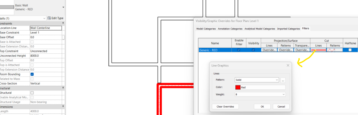
yes you can. Add a filter for wall using Type Name and apply that filter in View. hit VG and edit the filter CUT Properties according to your liking. Turn off Thin Lines to check the line thickness.
-

LISP to select lines and text according to "Z" values
shokoufeh replied to shokoufeh's topic in AutoLISP, Visual LISP & DCL
WOW. Great. It works Thank you -
LISP to select lines and text according to "Z" values
shokoufeh replied to shokoufeh's topic in AutoLISP, Visual LISP & DCL
I applied this and the problem is solved for Hatches, too. Thank you -

Get length of MLeader/QLeader spline.
Tsuky replied to SLW210's topic in AutoLISP, Visual LISP & DCL
@SLW210 You are rigth this is the good direction for your ask. Try this (defun c:length2lead ( / AcDoc Space ss dog_l n sel obj) (setq AcDoc (vla-get-ActiveDocument (vlax-get-acad-object)) Space (if (= 1 (getvar "CVPORT")) (vla-get-PaperSpace AcDoc) (vla-get-ModelSpace AcDoc) ) ) (vla-startundomark AcDoc) (princ "\nSelect mleader") (while (not (setq ss (ssget (list '(0 . "MULTILEADER") (cons 67 (if (eq (getvar "CVPORT") 1) 1 0)) (cons 410 (if (eq (getvar "CVPORT") 1) (getvar "CTAB") "Model")) ) ) ) ) ) (initget 7) (setq dog_l (getdist (getvar "VIEWCTR") "nNew length for multileader?: ")) (repeat (setq n (sslength ss)) (setq sel (ssname ss (setq n (1- n))) obj (vlax-ename->vla-object sel) ) (vla-put-DoglegLength obj dog_l) (vla-regen AcDoc acactiveviewport) ) (vla-endundomark AcDoc) (prin1) ) -
Get length of MLeader/QLeader spline.
BIGAL replied to SLW210's topic in AutoLISP, Visual LISP & DCL
As I suggested can move the vertices and return the new length or say draw something and move say the first point keep repeating till it is the length you want. Will have a play. - Yesterday
-
TEXT HEIGHT VALUE FOR ARCHITECHTURAL UNIT IN TEXT TAB OF DIMSTYLE MANAGER DILOG
SLW210 replied to LIU's topic in AutoCAD Beginners' Area
If Architectural units are being used, entering 2.6 in the Text Height box would make the text 2.6" in Architectural format that's shown as 2- 15/32". The equivalent to 2.6mm text height for Architectural is 1/8" or .125". -
Get length of MLeader/QLeader spline.
SLW210 replied to SLW210's topic in AutoLISP, Visual LISP & DCL
But wouldn't undo change it back to original length? Still looking to decipher this one, probably tomorrow when I get back to work. -

Getting and modifying attribute text inside a dynamic block
p7q replied to p7q's topic in AutoLISP, Visual LISP & DCL
Thanks ı got the part of ı needed. - Last week
-

LISP to select lines and text according to "Z" values
Nikon replied to shokoufeh's topic in AutoLISP, Visual LISP & DCL
If all the primitives (TEXT,MTEXT,INSERT,LINE,LWP,Circle,Mleader,Dimension) are perceived as objects, then you can use this code: ;; Set coordinates of objects (TEXT,MTEXT,INSERT,LINE,LWP,Circle,Mleader,Dimension) Z in 0 (defun zeroz-in-list (lst /) (cond ;; The list of coordinates-vertex ((and (listp lst) (= (length lst) 2) (numberp (car lst)) (numberp (cadr lst))) ;; if only XY - expanding to XYZ (list (car lst) (cadr lst) 0.0) ) ((and (listp lst) (= (length lst) 3) (numberp (car lst)) (numberp (cadr lst)) (numberp (caddr lst))) ;; if already XYZ - just do Z=0.0 (list (car lst) (cadr lst) 0.0) ) ;; If it's a large list, it's probably nested ((listp lst) (mapcar 'zeroz-in-list lst) ) (t lst) ) ) (defun c:ObjZ0 (/ ss n e el newel) (prompt " Select objects (all types, including polylines, mleader, dimension): ") (if (setq ss (ssget)) (progn (setq n 0) (while (< n (sslength ss)) (setq e (ssname ss n) el (entget e) newel nil ) (foreach pair el (cond ;; height LWPOLYLINE (code 38) ((and (= (car pair) 38) (numberp (cdr pair))) (setq newel (cons (cons 38 0.0) newel)) ) ;;Point codes (for example, 10, 11, 12...), etc. ((and (numberp (car pair)) (not (= (car pair) 210))) ; Don't touch the normal (if (listp (cdr pair)) (setq newel (cons (cons (car pair) (zeroz-in-list (cdr pair))) newel)) (setq newel (cons pair newel)) ) ) ;; The rest (t (setq newel (cons pair newel))) ) ) ;; Restoring order and modifying the object (entmod (reverse newel)) (setq n (1+ n)) ) ) ) (princ) ) If the Z coordinate is not displayed in the properties (example, for dimensions, for Mleader), then you need to use the _LIST command. Don't think of me as a programmer... The code is written using AI. -
LISP to select lines and text according to "Z" values
Steven P replied to shokoufeh's topic in AutoLISP, Visual LISP & DCL
Use what you have done previously but for dx code 10: (foreach dxf le (if (= (car dxf) 10) (setq le (subst (cons 10 (zeroz (cdr dxf))) dxf le)) ) ) -
LISP to select lines and text according to "Z" values
shokoufeh replied to shokoufeh's topic in AutoLISP, Visual LISP & DCL
Oh OK. Thanks for mentioning -

LISP to select lines and text according to "Z" values
GLAVCVS replied to shokoufeh's topic in AutoLISP, Visual LISP & DCL
Yes I briefly forgot that LWPOLYLINES don't have a Z coordinate and instead use group 38 to define their elevation. Therefore @shokoufeh: the code you added to set the Z for LWPOLYLINES is unnecessary -
LISP to select lines and text according to "Z" values
shokoufeh replied to shokoufeh's topic in AutoLISP, Visual LISP & DCL
so, how should I change the code? -
LISP to select lines and text according to "Z" values
Steven P replied to shokoufeh's topic in AutoLISP, Visual LISP & DCL
Missed your message but am intrigued now... (a guess I would say you were saying LWPolyline has X, Y, Z coords - I've done the same many times too) -
LISP to select lines and text according to "Z" values
Steven P replied to shokoufeh's topic in AutoLISP, Visual LISP & DCL
I think hatch is the first '10' if an elevation has been set (10 0.0 0.0 'Z') -
LISP to select lines and text according to "Z" values
shokoufeh replied to shokoufeh's topic in AutoLISP, Visual LISP & DCL
I was checking my files and I found out another problem. Except elements I mentioned (lines, poly lines, texts and blocks), the problem with Z values exist in other elements, as I mention below: Hatch: Elevation Leader: Vertex Z Ellipse: Start Z, Center Z, End Z Arc: Start Z, Center Z, End Z Circle: Center Z Solid: Elevation Attribute Definition: Text Alignment Z Array (Rectangular) : Base Z Please check this modified lisp and see if it is correct or not. This lisp doesn't work on HATCH. ZRemove.lsp -

TEXT HEIGHT VALUE FOR ARCHITECHTURAL UNIT IN TEXT TAB OF DIMSTYLE MANAGER DILOG
oddssatisfy replied to LIU's topic in AutoCAD Beginners' Area
Enter 2.6 in the Text Height box. -
LISP to select lines and text according to "Z" values
GLAVCVS replied to shokoufeh's topic in AutoLISP, Visual LISP & DCL
Sorry: That problem will never exist in a LWPOLYLINE: Forget what I said, if you managed to read the previous message