All Activity
- Past hour
-

Serious UI Failure in OpenDCL Studio - 'Options' and 'New Project' Menus are Missing
duke replied to duke's topic in AutoLISP, Visual LISP & DCL
Claro, aquí tienes la traducción. Te ofrezco dos versiones: una más directa y otra un poco más conversacional, ideal para un foro de ayuda. Opción 1 (Traducción Directa) I'm a beginner with DCL, so I may not be able to give a very clear explanation. An AI helped me download OpenDCL. First, it helped me understand simple DCL (without a separate program), but I would like a more flexible way to manage a dialog box or window to my liking—to place it wherever I want on the screen. Simple DCL only allows it to be positioned in the center of the current window. But when I try to use OpenDCL, it appears as shown in the screenshots. According to the AI, it is supposed to look different, and for that reason, it can't help me learn how to create windows with it. Thanks for any help you can provide. Opción 2 (Versión más Conversacional para Foros) Hello, I'm new to DCL, so please bear with me if my explanation isn't perfect. An AI assistant helped me download OpenDCL. It first helped me understand basic DCL, but my goal is to have more control over dialog boxes, specifically to be able to place them anywhere I want on the screen. The standard DCL seems to lock the position to the center of the current window. The problem is, when I try to use OpenDCL, it shows up in the way you see in the screenshots. The AI told me this isn't how it's supposed to look, and because of this issue, it can't guide me on how to learn to create windows. Any help you could offer would be greatly appreciated. Thank you.
-
Serious UI Failure in OpenDCL Studio - 'Options' and 'New Project' Menus are Missing
duke replied to duke's topic in AutoLISP, Visual LISP & DCL
-

Break an object at 2 points and replace the properties of the line
BIGAL replied to Nikon's topic in AutoLISP, Visual LISP & DCL
For me if you have an object and use Break. When selecting the first point you get an entity name ie ent1 Select 2nd point and run break pt1 pt2 Ok the second entity is (entlast) so no need for ssget's etc When you break say line pline the new object is created in the same direction so the gap is join endpoint ent1 to startpoint ent2. But as mentioned a circle and an arc need a slight variation on this. But still have a start and endpoint. Oh yeah a circle needs to be selected in an anti clockwise direction. Clockwise gives a short arc. Yes a break in the arc of a pline is an interesting problem. Or worse a part arc and straight. Later today will have a go. -
Multileader justify paragraph doesn't work
BIGAL replied to 3dwannab's topic in AutoCAD Bugs, Error Messages & Quirks
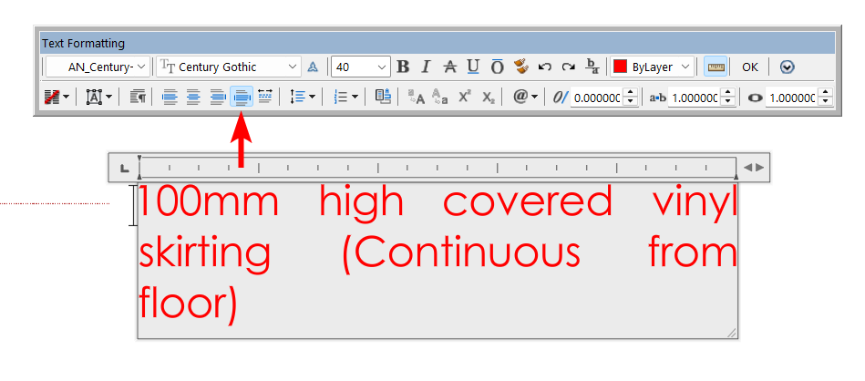
What does dumpit.lsp reveal it should show in the Textstring property TextString = "\\pxqc;This is a test of\\Psetting the text\\P to middle centre" The pxqc is centre justified, a pxql is left justified. You should have a copy of dumpit.lsp. - Today
-
Serious UI Failure in OpenDCL Studio - 'Options' and 'New Project' Menus are Missing
BIGAL replied to duke's topic in AutoLISP, Visual LISP & DCL
Do you need to use OpenDCl or can normal DCL be used ? Maybe explain what your trying to do in the DCL. There is some very smart DCL builders that post here. -
Function to calculate Mtext Justification based on Rotation
BIGAL replied to CivilTechSource's topic in AutoLISP, Visual LISP & DCL
@CivilTechSource "spent time creating that polyline" one way out of making a pline around multi objects provided there are no gaps is to use BPOLY, draw a random pline around the objects, use BPOLY and pick a point between the dummy pline and the objects you should get two new plines, erase the dummy and new outer pline, but you have now a new boundary pline. Use say layiso first to limit objects and set a dummy layer. Need a real dwg to see what is going on. - Yesterday
-

Break an object at 2 points and replace the properties of the line
mhupp replied to Nikon's topic in AutoLISP, Visual LISP & DCL
So went ahead and joined my first part of mine and what Blackbox & Glavcvs posted. Can either run it by typing BD or BreakDash ;;----------------------------------------------------------------------------;; ;; Break Entities and changed layer, linetype, color (defun C:BD () (C:BreakDash) (princ)) (defun C:BreakDash (/ SS1 SS2 SS3 pt1 pt2 ent entdata newent) (setq SS2 (ssadd)) (while (setq SS1 (ssget "_+.:E:S" '((0 . "*LINE,CIRCLE,ARC")))) (setq ent (ssname SS1 0) pt1 (getpoint "Select the first break point: ") pt2 (getpoint "Select the second break point: ") LastEnt (entlast) ) (command-s "_.BREAK" ent pt1 pt2) (while (setq LastEnt (entnext LastEnt)) (ssadd LastEnt SS2) ) (setq SS3 (ssget "_W" pt1 pt2 '((0 . "LINE")))) (foreach ent (vl-remove-if 'listp (mapcar 'cadr (ssnamex SS3))) (if (ssmemb ent SS2) (progn (entmod (append ent '((8 . "0") '(6 . "DASHED2") '(62 . 84)))) (entupd ent) ) ) ) ) (princ) ) And found Cab's post for break all objects -

Multileader justify paragraph doesn't work
3dwannab posted a topic in AutoCAD Bugs, Error Messages & Quirks
Hi all, ACAD 2026 Issue: MLEADER text does not update when setting paragraph alignment to Justify in the editor. Steps to Reproduce: Create a MLEADER with text. Open the text in the MTEXT editor. Set the paragraph alignment to Justify. Close the editor. Expected: Text should be justified. Actual: Text remains left-aligned; Justify has no effect.
-
try this : (defun Fill_Toolbar_Background (x- y- x+ y+ c / y vws bgf-fac delta-y) (setq y y- vws (getvar "viewsize") bgf-fac (/ 0.1 (/ (atof GrM-Button-Background-Fill) 100.0))) (setq delta-y (/ vws 1000.0)) (while (<= y y+)(grdraw (list x- y)(list x+ y) c)(setq y (+ y (* delta-y bgf-fac (/ vws start-viewsize)))))) did very little testing though... oh , about the 'duplicated' background fill , although there are two and the first could (should) have been deleted, it doesn't matter because lisp only evaluates the last version. Every new definition overwites the previous one.
-

Break an object at 2 points and replace the properties of the line
GLAVCVS replied to Nikon's topic in AutoLISP, Visual LISP & DCL
PS: Note that I have disabled (40 . 0.25) and (47 . 20) because they are rejected by most objects in your filter, and I haven't taken the time to find out which objects they actually apply to. -
Break an object at 2 points and replace the properties of the line
GLAVCVS replied to Nikon's topic in AutoLISP, Visual LISP & DCL
Hi As @mhupp mentioned, there are extra 'quotes' marks in your code. Also, as Mhupp suggested, you can use the filter "_+.:E:S" to select the object to be cropped in a single step, and then implement it within a 'while' loop to repeat the operation as many times as needed. Putting all of this together, your code could look something like this: (defun c:Br2ptReplDash (/ ss pt1 pt2 ent entdata newent entUlt) (while (setq ss (SETVAR "NOMUTT" 1) ss (princ "\nSelect object to trim (RIGH CLICK to EXIT)...") ss (ssget "_+.:E:S" '((0 . "*LINE,POLYLINE,CIRCLE,ARC"))) ) (SETVAR "NOMUTT" 0) (setq entUlt (entlast)) (princ "\nSelect the object to split: ") (setq ent (ssname ss 0)) ;; Entering the first break point (setq pt1 (getpoint "\nSelect the first break point: ")) ;; Entering the second break point (setq pt2 (getpoint "\nSelect the second break point: ")) ;; Checking the object type and performing the split (cond ((= (cdr (assoc 0 (entget ent))) "LWPOLYLINE") ;; break the LWPOLYLINE (command "_.BREAK" ent pt1 pt2) ) ((= (cdr (assoc 0 (entget ent))) "LINE") ;; break the line (command "_.BREAK" ent pt1 pt2) ) ((= (cdr (assoc 0 (entget ent))) "POLYLINE") ;; break polyline (command "_.BREAK" ent pt1 pt2) ) ((= (cdr (assoc 0 (entget ent))) "CIRCLE") ;; break the circle (command "_.BREAK" ent pt1 pt2) ) ((= (cdr (assoc 0 (entget ent))) "ARC") ;; break the arc (command "_.BREAK" ent pt1 pt2) ) (T (prompt "An object of an unsupported type.") ) ) (command "_.LINE" pt1 pt2 "") (if (not (equal entUlt (entlast))) (progn (entmod (append (ENTGET (ENTLAST)) '((8 . "0") ; the default layer (6 . "DASHED2") ; line type ;'(70 . 0) ;(40 . 0.25) ; thickness ;(47 . 20) (62 . 84) ) ) ; LTSCALE ) (princ "\nProcess completed for these objects") (vlr-beep-reaction) ) (princ "\n*** The operation could not be performed ***") ) ) (if (not entUlt) (princ "\nObjects are not selected.")) (princ) ) -
it uses drawing units to fill the background so if your drawing is very large , like site layout or big 3D drawing , yes , then it will take a long time. You can try setting fill in setup to 10% , or I could make it a factor like 1 (vector) line per 1/10 or 1/100 per viewsize. I usually work with standard drawings A4-A0 , also site layouts but most of the time electrical diagrams and instrument loop diagrams. You could switch to paperspace and see what happens. But I will look into making backgroud fill depend of viewsize, should be fairly simple. Probably also make sure ucs is set to view when using menu in 3d drawings , never use 3d for the kind of work I do.
-
I'm trying to get it to work in my AutoCAD 2021, but it takes a very long time to load (about 20 seconds). The problem seems to be with the 'Fill_Toolbar_Background' function (it appears to be duplicated). Could it be that my slow computer is the cause?
-

What Is CAD? Understand CAD: A Comprehensive Guide for Design and Drafting Professionals
The AutoCAD Blog posted a topic in AutoCAD Blogs
What is CAD? Computer-aided design (CAD) is a designation for software specifically created to assist in designing and drafting for architecture, engineering, product development, manufacturing, and nearly any other design purpose. With CAD software, designers can create, edit, and optimize their designs as either 2D drawings or as 3D models. From their humble beginnings in the early 1960s, when IBM and GM collaborated to invent DAC-1 (Design Augmented by a Computer), CAD programs have progressed slowly at first, and lately by leaps and bounds. When Autodesk was founded in 1982, it released AutoCAD, the first CAD software made for desktop personal computers. In the 1990s, CAD systems gradually displayed improved 3D modeling abilities. By the 2000s and beyond, CAD software began expanding its capabilities beyond just 2D and 3D design and modeling. Now, the most advanced CAD products are mighty, cloud-based platforms. They offer automated documentation assistance, powerful simulations of real-world behavior and functionality, photorealistic rendering for lifelike 2D and 3D visualizations, and even animation. Types of CAD Software Different types of modern CAD software are discerned by their ability to aid 2D design, 3D design, or both. 2D CAD Software CAD’s definition can get misconstrued as exclusively 3D design. However, 2D CAD software provides an essential platform for various industries that need precise, flat technical drawings to define shapes and layouts geometrically. Such applications include: Floor plans, construction site layouts, structural documentation, and permit-ready drawings in the architecture, engineering, construction, and operations (AECO) industry. Component and assembly schematics, CNC-ready drawings, technical illustrations, and piping and instrumentation diagrams (P&ID) for manufacturing and industrial engineering. Printed circuit board (PCB) design, control panel schematics, and circuit and wiring layouts for electrical and electronics applications. Furniture and room layouts for interior design. Packaging and labels for the product design industry. For all of these purposes, 2D CAD software like Autodesk AutoCAD LT ensures precise drafting accuracy with full sets of geometric tools that snap to endpoints, midpoints, intersections, and grid lines; layer management; annotation for dimensions, notes, and symbols; file interoperability; and drawing templates that help enforce industry standards. AutoCAD LT supplies all of the above, as well as best-in-class collaboration abilities with cloud connectivity, universal accessibility from web browsers, desktop, and mobile devices; and greatly streamlined workflows from AutoLISP, which offers thousands of pre-existing automations and helps to enforce CAD standards. 3D CAD Software A wealth of 3D CAD software offers deep 3D modeling, rendering, and even animation features, with various strengths and specializations depending on whether the 3D CAD program focuses on aspects of the AECO, product design, manufacturing, or education/training industries. Types of 3D modeling within 3D CAD software offer different tools and capabilities: Parametric modeling: By using constraints and dimensions, the model geometry updates dynamically when changes are made. Direct modeling: The model’s geometry can change with quick edits that aren’t tied to a history of constraints and dimensions. Assembly modeling: Two or more components are modeled into a functional system using motion constraints. Solid modeling: A component or assembly is modeled volumetrically for precision. Surface modeling: This specializes in modeling complex curved surfaces—often with high physical or aesthetic standards—for industrial or product design. Rendering capabilities in 3D CAD software can rival those used in the media and entertainment industries for visual effects and animation. These rendering capabilities allow designers and drafters to create photorealistic visualizations of their designs that accurately simulate materials, textures, and finishes, as well as reproduce lifelike directional or ambient lighting with advanced high-fidelity features like ray tracing, which convincingly reproduces reflections and shadows. Trends in CAD software show that stronger animation features in 3D CAD products are allowing designers to show off their creations in even more spectacular fashion by, for example, animating the exploded view of a product assembly, demonstrating the accurate mechanical movement of a product in detail, or to create sweeping fly-throughs or walk-around presentations using cinematic camera paths. Intuitive timeline editors controls these animations with keyframes and transitions similar to popular video editing apps. All 3D CAD products have similarities, but many of them differentiate by excelling particularly well for certain purposes. Revit, for example, specializes in Building Information Modeling (BIM) for architecture, infrastructure, and MEP (mechanical, electrical, and plumbing) systems. Inventor’s advanced parametric and assembly modeling with powerful simulations make it a favorite for industrial design and mechanical engineering. In addition to parametric, direct, and freeform CAD modeling, Fusion includes computer-aided manufacturing (CAM), computer-aided engineering (CAE), and PCB toolsets, making it ideal for product design and manufacturing, as well as electronics engineering. AutoCAD offers both 2D and 3D CAD tools for design and drafting and has been trusted amongst architecture, construction, and product engineering professionals for decades. All four of these Autodesk 3D CAD solutions include high-end rendering and animation functionality, AI-assisted workflow streamlining, and cloud connectivity with world-class collaboration abilities. Specialized CAD Toolsets In some cases, uniquely specialized CAD software products, or specific toolsets within larger CAD software, offer hyper-focused abilities, directly tailored for certain industries. AutoCAD specialty toolsets: AutoCAD has seven add-on toolsets that increase productivity with thousands of intelligent objects or symbols, as well as enhanced features. For example, AutoCAD Architecture Toolset‘s 8,800+ architectural components like doors, windows, and walls help with automated generation of floor plans, ceiling grids, and more. AutoCAD Mechanical Toolset automates BOM (bill of materials) creation and includes 700,000+ parts and features for mechanical engineering and manufacturing. AutoCAD Electrical Toolset automates wire numbering and component tagging with the aid of 65,000+ intelligent electrical symbols. The 10,500+ intelligent pipes, fittings, ducts, and other objects in the AutoCAD MEP Toolset greatly increase MEP design productivity. Civil 3D: For civil engineering design and documentation, Civil 3D supplies complex infrastructure tools in a 3D modeling environment. These include terrain modeling, corridor design, stormwater and sanitary sewer analysis, and automation assistance for tasks like grading optimization, pipe layout, and more. Advance Steel: Built for structural steel detailing and fabrication, Advance Steel 3D steel design software assists with parametric steel connections, folded plate modeling, and stairs, railings, and cage ladders. It automatically generates steel fabrication deliverables like shop drawings and NC files. Its Dynamo Extension also automates repetitive tasks like making parametric steel connections. Advance Steel integrates with Revit, Navisworks, and others to make your workflow smooth. Benefits of Using CAD Out of CAD’s many benefits, the major advantages include improved accuracy, efficiency, collaboration, presentation, and everybody’s favorite: cost savings. Increased drafting precision and accuracy Designers enjoy the highest level of accuracy in their CAD models, all the way down to the micrometer (one millionth of a meter). This precision comes at a fast pace as well. Dimension tools, constraints, and snap grids help designers and drafters work quickly, while doing away with manual drafting errors. With parametric modeling, precise geometries stay accurate and consistent despite numerous revisions. Improved design quality and efficiency CAD tools speed up design and drafting tasks in myriad ways. Preloaded templates jumpstart similar projects and often build-in standards to adhere to. Libraries of common reusable components, symbols, and other elements maintain consistency while boosting work speed. Advanced CAD software can also automate a number of processes, such as generating BOMs and annotations. Enhanced collaboration and communication Integrated documentation within CAD software improves clear communication with both internal and external collaborators, like manufacturers. It’s easy to track revisions with markup tools and version control. Autdodesk’s CAD options with cloud connectivity also allow multiple users to collaborate on a project simultaneously from any device. Cost savings and less rework Simulation and analysis tools in CAD software help to detect design flaws early in the process, cutting down on rework stemming from errors and contributing to cost efficiency. Highly detailed and accurate documentation also reduces mistakes, rework, and material waste in the fabrication stage. Automation functions in some CAD software reduce the time needed for tedious, repetitive design and drafting tasks, allowing more work to be done in less time. Better visualization and presentation The photorealistic and engaging results of high-end CAD software’s 3D rendering and animated walkthroughs or exploded views impress stakeholders with vivid presentations. This helps especially when seeking approvals from non-technical audiences. These animation and simulation tools can convey real-world functionality, so you can make tweaks before expending resources on physical prototypes. CAD applications across industries Industries benefitting most from CAD include AECO, product design and manufacturing, and other related custom design industries. Architecture, engineering, and construction (AEC) Every piece of the AEC industry feels the impact of CAD technology, from initial architectural concepts to the monitoring of a BIM digital twin for building lifecycle management. CAD fuels the architectural design process, including floor plans, elevations, and sections. It’s also critical for presenting building and interior designs with animated 3D walkthroughs and stunning architectural visualizations. Specialty tools like Revit and Advance Steel provide structural engineers with vital abilities like load analysis, reinforcement, and steel detailing. Meanwhile, options like AutoCAD MEP use intelligent object modeling to streamline the design of HVAC, electrical, and plumbing systems. Larger infrastructure and civil works projects also benefit from CAD software like Civil 3D to facilitate terrain modeling, grading, and other site planning and infrastructure design jobs. These same CAD tools can continue to feed data into the BIM digital twin of a finished building for lifecycle management and clash detection. Manufacturing The influence of CAD applications has helped the manufacturing industry reach new heights of precision and efficiency. For example, parametric modeling tools like Inventor are critical for designing the highest-performance mechanical components, assemblies, and tooling. Sheet metal and mold design are more efficient than ever with special features for sheet metal unfolding and nesting and for creating injection molds. Advanced CAD software’s capacity for high-level simulation allows virtual thermal and stress testing, as well as analyzing a product’s material behavior and motion dynamics before the prototyping and fabrication stages. Some CAD software, like Fusion, integrate CAM and can export data directly to CNC machines and 3D printers for rapid prototyping and custom or small-batch production. CAD modeling tools also integrate with product lifecycle management (PLM) systems to inform their version control and compliance. Product design Designers of some of the most intricate and high-performance products get special creative and functional assistance from CAD software. For example, industrial designers can experiment with the most sculpted surfaces, the most ergonomic modeling, and the most refined aesthetics with a tool like Autodesk Alias. And electronics engineers have dedicated capabilities in Fusion like PCB layout, thermal simulations, and enclosure design. Fusion also includes extensive generative design abilities to explore thousands of quickly generated design permutations based on the designer’s constraints. The software can also export the design to CNC machines or 3D printers for iterative prototyping. Product design also gains marketing and client visibility with CAD software’s built-in visualization and rendering for creating photorealistic graphic and animated presentations. General design and drafting applications Apparel designers make use of CAD for drafting patterns, simulating garments, and textile layout. Interior designers can strategize furniture and cabinetry layouts and visualize materials. Commercial designers model and test packaging solutions, design signage, and layout trade booth or retail displays. Jewelry designers appreciate the exacting precision of CAD software for casting and stone setting. The Future of CAD A wealth of exciting emerging trends in CAD technology point to CAD tools becoming even more central creative hubs for the industries they serve, with wide-ranging implications for the design and drafting professions. Emerging trends in CAD Most of these future trends in CAD are already underway in the advanced CAD tools that are available now, but they will become even more important for industry professionals and industries to adopt. For example, cloud-based CAD software—like Autodesk’s CAD tools—will become an essential feature of workflows, as they allow designers and all their colleagues and stakeholders to work and collaborate from anywhere on any device. Distributed hybrid and remote teams immediately see the advantages of simultaneous multiple users being able to review, edit, and comment. Cloud platforms like Fusion perform processing in the cloud, putting less pressure on users’ machines and allowing businesses to scale. AI functions will also become more prevalent. Machine learning already drives generative design and predictive analysis to detect potential performance issues and suggest geometries and materials. Other automation tools on the market include AI-assisted block placement and quantity tracking in AutoCAD LT and automated dimensioning, component placement, and error checking. CAD companies’ continued research into integrating AI will automate more repetitive tasks for greater accuracy and to free up designers and drafters for the more creative aspects of their work. CAD software’s visualization capabilities are already quite impressive, but as VR and AR technology matures and gains wider adoption, CAD tools will offer immersive XR (extended reality) presentations of building walk-throughs, automotive walk-arounds, and so on. These presentations could happen remotely in VR or in physical locations using AR overlays to see how 3D models would look in the real world. As the methods and materials behind 3D printing continue to advance, there will be greater options for not only rapid prototyping but also more viable production runs using additive manufacturing and hybrid manufacturing—a combination of additive manufacturing and subtractive manufacturing from CNC machines. This will make design for additive manufacturing (DfAM) a more significant consideration for product designers and engineers if additive can provide an equal-quality product faster and/or for less money. And CAD tools like Fusion with integrated CAM will be able to handle the iterative development of a product from concept to production—all within a single platform. Sustainability and the quest for a circular economy are here to stay and even more viable thanks to the trends in CAD technology. CAD software’s simulation abilities include energy use simulations, daylight analysis for optimizing the natural light and temperature implications in buildings, and material impact assessments to help make more eco-conscious material choices. CAD software also enables digital twins—real-time replicas of physical products, buildings, and larger systems—which use big data streams and AI for predictive maintenance and lifecycle optimization. Future impact on designers and drafters All these emerging trends in CAD enforce what was already a momentous shift away from CAD being just a drafting tool to CAD platforms being centralized creative and collaborative hubs for designers and businesses. This shift will impact design and drafting professions. For one thing, there’s inertia away from 2D drafting and more toward intelligent 3D modeling capable of collecting product lifecycle data for informing BIM and product digital twins. Professionals in these fields would do well to add parametric modeling, CAD simulation, and interdisciplinary coordination skills to their repertoire. The jobs may evolve further into being more like design strategists and creative technologists, where they use more automation and AI tools to realize their creativity and to optimize collaborative workflows. Return-to-office (RTO) orders are trendy in certain tech-focused businesses for now, but what will happen when cloud-based CAD becomes the norm and enables cross-border remote teamwork to be as effective and fruitful as ever? Also, the increasing accessibility of advanced CAD features, AI tools, and cloud-based processing should theoretically empower smaller studios and individuals to compete with larger operations for jobs. Design and CAD modeling education is also evolving to become more accessible to more people and to emphasize concepts like digital manufacturing, systems thinking, and sustainability. Employers and employees alike will need to embrace lifelong learning in order to advance along with the evolving CAD technology. Careers in CAD Discover the opportunities, industry demand, and qualifications needed for today’s CAD careers. Career paths and opportunities As CAD tools and platforms become more capable and more central to design businesses, there’s never been a more exciting time to pursue these CAD careers. CAD drafters/technicians produce 2D or 3D technical drawings for the AECO and manufacturing industries. CAD designers create detailed 3D models and prototypes, often with their own freedom to make design decisions. CAD engineers in fields like civil infrastructure or mechanical engineering add engineering analysis—like finite element analysis (FEA)—to CAD design duties. BIM coordinators manage building information models in the AECO industry. Specialist CAD roles hone in on specific areas like piping layouts, electrical schematics, or fashion pattern drafting. CAD leadership roles advance from previous positions into jobs like project manager, CAD manager, and design lead. Required skills and qualifications To begin a CAD career, the top requirement is proficiency in one or more of the leading CAD toolsets, such as AutoCAD, Revit, Fusion, Civil 3D, or Inventor. Technical knowledge is also key, including engineering principles, geometry, spatial reasoning, and drafting standards. Soft skills are also highly desirable. These include things like attention to detail in order to avoid errors in manufacturability, compliance and so on. Communication and collaboration soft skills are also more important than ever to work with interdisciplinary team members and clients who may be entirely non-technical. Skilled people who can demonstrate CAD proficiency without educational credentials can find employment. However, a bachelor’s degree or at least an associate’s degree in drafting, design, or engineering is typical for CAD careers. One can also boost both their skills and credibility by earning certs, such as the many Autodesk Certifications. Industry demand and job outlook for CAD careers The outlook for CAD careers is still strong, although traditional drafting jobs are on a bit of a decline, while hybrid roles that combine CAD with a BIM specialty or engineering are in more demand. The AECO industry needs CAD professionals for BIM design and operations, MEP systems, building plans, and more. Likewise in civil engineering and infrastructure, CAD skills are essential in the design, building, and support of projects such as roads, bridges, waterworks, and other utilities. In manufacturing and product design, CAD pros are vital for prototyping, tooling, and other aspects of CAM integration. Across industries, there are growing opportunities to merge CAD skills with the expanding areas of XR (VR, AR, and mixed reality), sustainable design, and 3D printing/additive manufacturing. Professional development and advancement Workers at every stage of their CAD careers will likely benefit from continual learning, upskilling, and focusing strategically on in-demand skills, like generative design, simulation, and parametric modeling. Continuing education, whether advanced degrees or modular options like courses and certifications, can build your reputation and yield projects to show in a professional portfolio. Networking through professional associations or conferences can help advance a CAD career while also being learning opportunities. Getting Started with CAD While there’s no wrong way to get started with CAD, some thoughtful choices will help to use your time wisely. Think about your end goals, like if you want to learn 2D CAD drafting, 3D CAD modeling, or both, and whether you want to specialize in CAD for a particular industry. Also consider whether you need software made for beginners or are already comfortable with technical software. Do you need free software, or do you have a budget? Free software usually has a limited feature set, but can be very handy for first-time learners. Do you prefer browser-based web apps, or are you okay with downloaded software? For 2D drafting, AutoCAD LT is a great place to start. For beginner-friendly 3D CAD, Fusion has an inviting interface, a limited free version for personal use, and tons of free tutorials to get started. The place to go for a free 3D CAD web app for absolute beginners is Tinkercad, and make sure to check out the free tutorials in the Tinkercad Learning Center. However, if you’re ready to jump into serious CAD software that offers both 2D and 3D CAD and is entrenched across various industries, consider one of the versions of AutoCAD. The best option for students, casual users, and less active CAD collaborators is AutoCAD Web, the affordable, web and mobile version with limited but essential AutoCAD features for basic designs and light editing. AutoCAD Web’s features also come included with AutoCAD LT and the full version of AutoCAD, the go-to solution for industrial designers and AECO professionals needing 2D/3D technical drawings and CAD models. It has customizable workflows and many helpful automations that make large-scale projects more manageable. If you specialize in a certain field, seven AutoCAD Toolsets provide thousands of intelligently adapting objects and elements for your designs, as well as purpose-built workflow enhancements for specific professional needs. These toolsets serve architects (Architecture toolset), mechanical engineers (Mechanical toolset), electrical engineers (Electrical toolset), MEP contractors (MEP toolset), plant designers (Plant 3D toolset), GIS professionals (Map 3D toolset), and surveyors and archivists (Raster Design toolset). Exploring the Future Advancements of CAD Tools While CAD’s definition of computer-aided design has remained, CAD’s meaning to design and drafting professionals and businesses has undergone seismic shifts over decades of development. Using advanced CAD tools to their fullest extent benefits users with much greater precision and accuracy, design quality, and efficiency. Cloud-connected CAD platforms improve communication and collaboration. Rendering and animation make for better presentations and visualizations. Perhaps most importantly, by increasing accuracy while also streamlining workflows, CAD tools reduce both rework and overall production costs—essential as firms face tighter budgets. The near future promises even more CAD advancements and more incentives for industries to optimize their CAD use. New AI-assisted automations will continue to streamline workflows. Maturing 3D printing technologies will allow CAD/CAM systems to command new prototyping and custom manufacturing options. XR will expand CAD’s presentation and collaboration possibilities. Also, CAD tools will play a larger part in sustainability, helping designers and builders choose more eco-friendly materials, design more recyclable or reusable products, and produce more locally. All of this makes the industries relying on CAD exciting places to be, while also spelling change on the horizon for design and drafting professionals. Adopting new skills and technologies, as well as a mindset of lifelong learning can help to stay relevant and employed in the expanding, creative world of CAD. The post What Is CAD? Understand CAD: A Comprehensive Guide for Design and Drafting Professionals appeared first on AutoCAD Blog. View the full article -

Break an object at 2 points and replace the properties of the line
BlackBox replied to Nikon's topic in AutoLISP, Visual LISP & DCL
Entlast & entnext may help to mitigate that. 1+ -
Break an object at 2 points and replace the properties of the line
mhupp replied to Nikon's topic in AutoLISP, Visual LISP & DCL
You start the lisp with if this will only run once. changing the if to while will allow you to use the break command multiple of times with out having to type the command over and over. only draw back is if you only want to run the command once you have to right click or hit enter to exit the command. using ssget with the "_+.:E:S" acts like entsel and will only select entity's you define. eliminating the need to test the entity type. since you have the two break points defined you can use ssget with the window option to "select" that entity but could pick up other smaller unwanted items also. this is all moot because id recommend using Breakall by CAB. don't know if its on here but he posted it on theswamp.org many years ago. alot more features and error handling. -

Break an object at 2 points and replace the properties of the line
Nikon replied to Nikon's topic in AutoLISP, Visual LISP & DCL
I understand (), but the rest is not very clear... -
Break an object at 2 points and replace the properties of the line
mhupp replied to Nikon's topic in AutoLISP, Visual LISP & DCL
This is a bit more streamlined. ;; AutoLISP, which allows you to select objects (line, polyline, circle, arc), ;; break them at two points and replace the selected section with a dashed line with the specified parameters (defun c:Br2ptReplDash (/ SS pt1 pt2 ent entdata newent) ;while instead of if allows this command to be repated as long as you select an entity. (while (setq SS (ssget "_+.:E:S" '((0 . "LINE,POLYLINE,CIRCLE,ARC")))) ;Will emulate an entsel selection behaviour and only allows the entity types listed (progn ;no need for cond check now (setq ent (ssname SS 0)) (setq pt1 (getpoint "Select the first break point: ")) (setq pt2 (getpoint "Select the second break point: ")) Using the two points create a selection set window to pick up created break line (ssget "_W" pt1 pt2 '((0 . "LINE"))) Your entmod has to many ( ) (entmod (append newent '((8 . "0") ; the default layer '(6 . "DASHED2") ; line type '(40 . 0.25) ; thickness '(47 . 20) ; LTSCALE '(62 . 84) ; Add here instead of 2nd (entmod (append newent '((62 . 84)))) ) ) ) ;removed 2nd '(6 . "DASHED2") -

Break an object at 2 points and replace the properties of the line
CivilTechSource replied to Nikon's topic in AutoLISP, Visual LISP & DCL
few issues with the lisp. 1) The ssget does not seem to work. 2) Creating a new line between breakpoints will not work for circles as you need to create an arc. It will also not work on curved polylines. Maybe a better way to approach it, is to select the object copy it. Trim it to pt1 & pt2 and then, break the selected objected between pt1 & pt2? -

Serious UI Failure in OpenDCL Studio - 'Options' and 'New Project' Menus are Missing
SLW210 replied to duke's topic in AutoLISP, Visual LISP & DCL
I do not see any screen shots. Current Build [9.3.1.1] (The current build is always under development. It is where we add new features for testing. It's usually very stable, but may contain a few bugs.) Did you try the stable version? Stable Build [9.1.5.2] (The stable build has all the known bugs worked out, but may not be as up-to-date as the current build.) According to the response on the OpenDCL forum, those sub menus do not exist. Serious UI Failure in OpenDCL Studio - 'Options' and 'New Project' Menus are Mis As far as I can tell, AutoCAD 2021 was the first version for Windows 11, so there could be issues there. -
Break an object at 2 points and replace the properties of the line
Nikon posted a topic in AutoLISP, Visual LISP & DCL
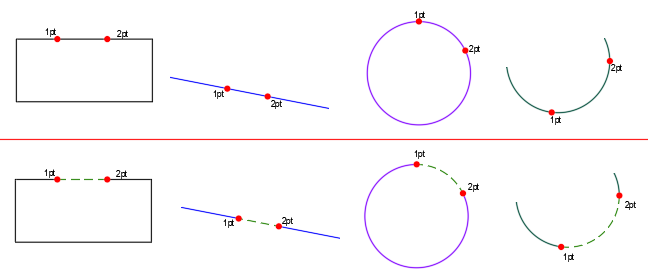
The code should draw a dotted new line between the points, but the line is not drawn. Would it be easier to change the properties of the line between two points? Thanks... ;; AutoLISP, which allows you to select objects (line, polyline, circle, arc), ;; break them at two points and replace the selected section with a dashed line with the specified parameters (defun c:Br2ptReplDash (/ ss pt1 pt2 ent entdata newent) (setq ss (ssget '((0 . "LINE,POLYLINE,CIRCLE,ARC")))) (if ss (progn (prompt "Select the object to split: ") (setq ent (ssname ss 0)) ;; Entering the first break point (setq pt1 (getpoint " Select the first break point: ")) ;; Entering the second break point (setq pt2 (getpoint " Select the second break point: ")) ;; Checking the object type and performing the split (cond ((= (cdr (assoc 0 (entget ent))) "LINE") ;; break the line (command "_.BREAK" ent pt1 pt2) ) ((= (cdr (assoc 0 (entget ent))) "POLYLINE") ;; break polyline (command "_.BREAK" ent pt1 pt2) ) ((= (cdr (assoc 0 (entget ent))) "CIRCLE") ;; break the circle (command "_.BREAK" ent pt1 pt2) ) ((= (cdr (assoc 0 (entget ent))) "ARC") ;; break the arc (command "_.BREAK" ent pt1 pt2) ) (T (prompt "An object of an unsupported type.") ) ) ;; Get new objects after splitting (setq ss (ssget "_N" '((0 . "LINE POLYLINE CIRCLE ARC")))) ;; Sorting through objects and replacing the section with a dotted line (setq i 0) (repeat (sslength ss) (setq ent (ssname ss i)) (setq entdata (entget ent)) ;; Create a new line between the break points (setq newent (command "_.LINE" pt1 pt2 "")) ;; Setting up line properties (entmod (append newent '((8 . "0") ; the default layer '(6 . "DASHED2") ; line type ;'(70 . 0) '(40 . 0.25) ; thickness '(47 . 20))) ; LTSCALE ) ;; Color setting (entmod (append newent '((62 . 84)))) (setq i (1+ i)) ) (prompt "Processing is completed.") ) (prompt "Objects are not selected.") ) (princ) ) Br2ptReplDash.dwg
-
Function to calculate Mtext Justification based on Rotation
GLAVCVS replied to CivilTechSource's topic in AutoLISP, Visual LISP & DCL
Even if you create MTEXT objects without referencing any other object, they will still have some kind of arbitrary geometry. You could establish a rule that the perimeter points are always entered in a clockwise order This would allow the code to have the necessary criteria to determine what is inside and outside the perimeter. Additionally, the code could dynamically draw a perimeter based on each insertion point specified by the user. As a convention for these temporary perimeters, you could assign them a specific, distinct color. All of this could later allow you to write code for another command that manages these perimeters and their associated MTEXT objects, and then replaces them with the final, definitive version. -
Function to calculate Mtext Justification based on Rotation
CivilTechSource replied to CivilTechSource's topic in AutoLISP, Visual LISP & DCL
@GLAVCVS You are absolutely correct. Ideally the user will select the polyline which represents a house and we calculate to place the text outside. However, we do not always get the building outline from the architects as a single polyline and I do not wish to spent time creating that polyline (for now). So I am focusing on at least having the correct Left/Right justification.... Unless I use something similar to LeeMacs Text Alignment Controls https://www.lee-mac.com/curvealignedtext.html . But at the moment this is slightly over my head for now. However, we could solve this issue without taking in consideration of geometry and take a similar approach to how you set the UCS, by selecting 3 points. p1-TextPlacement p2-Text Left & Right Justification based on p1 p3-Text Top & Right Justification based on p1 & p2 Would that work? -
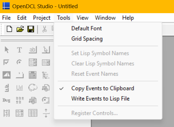
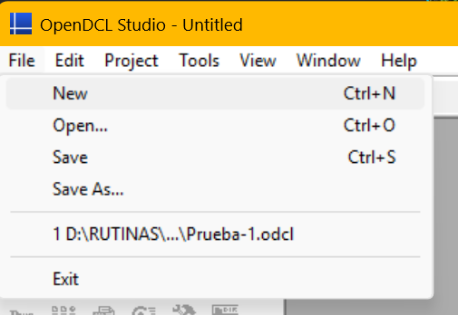
Hello everyone, I'm new to OpenDCL and I'm having a very strange issue with my installation. The OpenDCL Studio interface is not displaying correctly, which is preventing me from getting started. **The Problem:** Key menu items are completely missing. 1. In the "Tools" menu, the "Options..." item is missing. 2. In the "File > New" menu, the "Project" option is missing, so I cannot create a new project. **My System Information:** - Operating System: Windows 11 - AutoCAD Version: AutoCAD 2020 (English) - OpenDCL Version: 9.3.1.1 **What I've already tried without success:** - A complete uninstall/reinstall of OpenDCL. - Rebooting the PC. - Trying both the Spanish (ESM) and the main English installers. In all cases, the result is exactly the same. I have attached screenshots showing the missing menu items. Has anyone seen this fundamental issue before or have any ideas what might be causing this conflict on my system? I know this forum is for general LISP, but I'm hoping someone here might have run into this OpenDCL issue before. Any help would be greatly appreciated. Thank you.
-
Get length of MLeader/QLeader spline.
BIGAL replied to SLW210's topic in AutoLISP, Visual LISP & DCL
New answer, when you draw a pline did you know you can pick start point, drag mouse for next point, BUT type in length no need for "L". Tested seems to work ok in original code. Starting point of Mleader Enter to stop : : _pline Select start of polyline or [Follow] <Last point>: Set next point or [draw Arcs/Distance/Follow/Halfwidth/Width]: 50 Set next point or [draw Arcs/Distance/Follow/Halfwidth/Width/Undo]: 75 Set next point or [draw Arcs/Close/Distance/Follow/Halfwidth/Width/Undo]: 100 Set next point or [draw Arcs/Close/Distance/Follow/Halfwidth/Width/Undo]: Existing length is 225 Enter new length 220 Enter label AAA Ok fixed the defun code, its messages may have been misleading. (defun plpts ( / pt) (command "_pline" (getpoint "\nStarting point of Mleader : ")) (while (= (getvar "cmdactive") 1 ) (command (getpoint (getvar 'lastpoint))) ) )