All Activity
- Past hour
-

5 CAD Commands That Can Save You More Time Than You Think
Dadgad replied to indiancad's topic in AutoCAD 2D Drafting, Object Properties & Interface
I am a big fan of the "Layers 2" Toolbar, where I first encountered LAYWALK. It was much more useful to me when my drawings had appreciably less than the thousands of layers which have become the norm. I really like LAYISO (LI) and LAYUNISO (LU). I prefer unisolated layers to be turned off, rather than dimmed. I am a huge advocate for setting up and using QUICK PROPERTIES. The modest amount of time invested, customizing it to your personal preferences will pay huge rewards henceforth.
-

AutoCAD Linetypes – Using Ours or Making Yours: Tuesday Tips With Frank
SLW210 replied to The AutoCAD Blog's topic in AutoCAD Blogs
I am surprised I never was fired for using the wrong dimension type in my isometric drawings. I am guessing they are generating articles now with AI. I queried DuckDuckGo Isometric vs Metric and the AI helper went off on the difference between isometric exercises and the Metric system of measurement, so on that vein I guess it's a miracle it's not considered a linetype for exercising (perhaps demon). So not a typo, just an uninformed AI assistant. - Today
-
.thumb.jpg.615654602253be56b2fbd5d064834780.jpg)
Why does a 3D model look correct but fail when using SUBTRACT?
indiancad posted a topic in AutoCAD 3D Modelling & Rendering
Have you ever had two solids that clearly intersect, but SUBTRACT doesn't produce the expected result? One thing I check is whether the solids actually overlap in 3D. They may appear to intersect from the current view while only touching or being separated along another axis. Using 3DORBIT to inspect the intersection from different angles usually makes the problem obvious. Have you ever found that two solids only appeared to intersect because of the viewing angle? -
Yeah, me too...sounds like the NEW and annoying "normal" .
-
 Sonic joined the community
 -

AutoCAD Linetypes – Using Ours or Making Yours: Tuesday Tips With Frank
Paul Li replied to The AutoCAD Blog's topic in AutoCAD Blogs
ISO is the official abbreviation for International Organization for Standardization and in the case of acadiso.lin this contains linetype definition designed around the metric measuring system -
 Radharavidas joined the community
 -

Why does a 3D solid become difficult to edit after using UNION?
lrm replied to indiancad's topic in AutoCAD 3D Modelling & Rendering
Unlike some solid modelers, AutoCAD does not readily provide the ability to go back and edit the primitives and olther solids that were used in Boolean operations. The command SOLIDEDIT provides some feature for editing a solid. Familiarize yourself with the command and its features. Alternatively, I often use explode and then do some edit making sure I continue to define a closed (watertight) shape so I can then use SURFSCULPT to make the model solid. - Yesterday
-

AutoCAD Linetypes – Using Ours or Making Yours: Tuesday Tips With Frank
BIGAL replied to The AutoCAD Blog's topic in AutoCAD Blogs
I think your incorrect. "AutoCAD has two such files, the other being “acadiso.lin for use in isometric drawings." If you look carefully at the two lin files it is very obvious they are imperial and metric, not "isometric", the values are obvious eg 0.375 is 3/8" or 10mm in other lin file. For me isometric is a typo. -
Free Browser-Based STEP/STP Viewer for Quick CAD Inspection
SLW210 replied to cadprops's topic in AutoCAD 3D Modelling & Rendering
That's better. One about 7.5 MB file gave an error. A few small 3.5 MB file -

Issues with MText in different colours
GGuzzler replied to GGuzzler's topic in AutoCAD 2D Drafting, Object Properties & Interface
Lenovo Yoga laptop, will check specs later. Print preview looks normal, then printing via DWG to PDF.pc3 causes the issue. Have tried reinstalling using pc3 in UserDataCache but without any change to result. Lato Regular is the font where I have the issue. Annoyingly this problem has only just started happening within the last couple of months. -
Thank you Mhupp for looking into this. I'm on v26.1.05 and planned to update before posting question to Bricscad support. I've also experiencing delays of over a second in layer properties toolbar registering layer changes by lisp command.
-
Issues with MText in different colours
SLW210 replied to GGuzzler's topic in AutoCAD 2D Drafting, Object Properties & Interface
What does a Print Preview look like and one printed to paper look like? What are you using to plot to PDF? Computer Specifications? No issues here on Pdf. vCT P2v0.1 YOC-P2 no AA.pdf vCT P2v0.1 YOC-P2 no AA-2.pdf -
Does anybody else have this DIMBREAK issue?
SLW210 replied to SLW210's topic in AutoCAD Bugs, Error Messages & Quirks
Thanks, I fixed those drawings, but your LISP works great. I have been having a ton of issues like this since work upgraded me to Windows 11 a while back. I have a reference number for Autodesk to look into it, but I keep getting the run around. -
A bit of googling check your version is past 26.2.07. can't check because i don't have V26 A regression in BricsCAD V26.2.5 caused the Properties window and other GUI components to stop updating during LISP execution, particularly when waiting for user input. This issue was identified as a regression and has been fixed in V26.2.07 (and subsequent builds). If you are experiencing this behavior: Update BricsCAD: Ensure you are running V26.2.07 or a newer version where the fix is included. Check System Variables: LISP scripts may inadvertently set FILEDIA or CMDDIA to zero, preventing dialog updates. Ensure your code resets these variables or uses an error handler to restore them upon cancellation. Alternative Property Access: For object properties not updating via COM, BricsCAD supports non-COM functions like (getpropertyvalue), (setpropertyvalue), (ispropertyreadonly), and (dumpallproperties) which work across Windows, Mac, and Linux.
-

AutoCAD Linetypes – Using Ours or Making Yours: Tuesday Tips With Frank
The AutoCAD Blog posted a topic in AutoCAD Blogs
It was one of the first things we were taught in my high school drafting class. Just as it is today, linetypes are a core feature of proper drafting. I can still remember picking up that freshly pointed HB pencil and gliding it against my T-Square, while properly rolling it along the way to ensure an even line. The point is, we were the drafter, and we were responsible for knowing what to do, what type of line to use, and correctly applying that skill. A skill which in the world of CAD is generally rendered moot. But that’s OK. This is one of those posts where, if your CAD department is set up correctly, most users will never need to load and manage linetypes. I know my users never did. So, while it is, as I said, a core feature, I’ll go over the basics first, then jump into a cool tip that makes creating your own custom linetypes easy. This isn’t called Tuesday Tips for nothing! A Linetypes Primer If you start a new drawing using the acad.dwt template file, you’ll get three linetypes: ByLayer, ByBlock, and Continuous. To get more, you have to load them. Launch the Linetype Manager dialog by selecting the Other option in the Linetype pulldown menu in the Properties panel of the Home tab of the ribbon. Or type in LT. Your choice. The next step is to click on the Load button. Doing so will display the Load or Reload dialog as shown below. Each type will have a name, a description that may better explain the linetype, and a graphic representation of what it looks like. Select the linetype you want, and click OK. It will now display in the Linetype Manager list, available for you to use in your current drawing. Again, you may have never actually done this, as it should have already been done for you. But now you know. Notice the dialog wants you to select a file, and defaults to something called “acad.lin”. The acad.lin file is simply a text file containing all of the linetype definitions. Let’s explore that file a little closer. The ACAD.lin File AutoCAD has two such files, the other being “acadiso.lin” for use in isometric drawings. They are stored in, and loaded from a folder in your user profile. More on that in a minute. Below is an image showing what it looks like. I’ve scrolled down a bit, mostly to show some comments referencing Release 13 and 14, but also to show the more complex linetype definitions. Let’s look at the definition for GAS_LINE, as we’ll be using that an example for the tip part of this post. You have the name and description – including the graphic representation – followed on the next line by the rather cryptic definition of how the linetype is created. Trust me, you do not want to learn how to define these things. Check out the ACAD_ISO… definition at the top of the image. I’m sure that the definition of “A,12,-3,12,-3,0,-3,0,-3,0,-3” makes total sense to you. Yeah, me too. The Actual Tip: Creating Your Own Linetypes By my count, there are 45 linetypes defined in the acad.lin file. Surely that’s enough to cover every situation ever imaginable, right? Of course not. But having just filled you in on how they’re defined, where would you even start if you had to create a custom linetype? That’s where AutoCAD’s Express Tools saves the day. Tucked safely away in the Additional Commands menu of the ET Tools panel, you’ll find Make Linetype. Let’s say we need to make the following (beautiful) linetype. The first step is pretty easy. Draw what you want it to look like. The second step is to launch the Express Tool, and follow its prompts. The next thing is tell it where to put the new definition. This location has changed often over the years, and now it defaults to your My Documents folder, using the format of <drawingName.lin>. Use that if you like. Or, you can go find the acad.lin file and your new linetype will be appended to the last section of the file. You can find it in the following location: C:\Users\<yourUserName>\AppData\Roaming\Autodesk\AutoCAD 202x\R2x.0\enu If you don’t feel comfortable about editing this file, just use the default, and then you can cut and paste later. The next step is to select the start point and end point of your sample linetype. Don’t forget to have an Endpoint Osnap turned on. Then, you’re asked to “Select Objects”. Select each element from left to right. Press Enter. Your custom linetype will be added to the .lin file, and will be loaded for the current drawing. It’s literally as easy as that. Now, I can draw whatever I want, using my “best ever” new custom linetype. While you can write your own .lin file as I described, I suggest moving your new style into the Acad.lin file, just to make things easier going forward. All of your styles should be defined in the same file. Speaking of the definition, here’s what the MKLYPE AutoLISP routine created for us. That’s All Folks Will you use the built-in linetype loading function, or create custom linetypes every day? I hope not. But like a lot of things in AutoCAD, it’s good to know they’re there, because (as I’ve learned over the years), you never know. More Tuesday Tips Check out our whole Tuesday Tips series for ideas on how to make AutoCAD work for you. The post AutoCAD Linetypes – Using Ours or Making Yours: Tuesday Tips With Frank appeared first on AutoCAD Blog. View the full article -

Does anybody else have this DIMBREAK issue?
DavidP replied to SLW210's topic in AutoCAD Bugs, Error Messages & Quirks
I never used dimbreak before so but can you use a lisp select all the dim and test which ones which have DimBreaks applied to the then just re-set them.? Test on a few drawings first (make sure run it on back version)... I did this with the help of ai... but it appears to work for me... (perhaps some can verify and improve on it) I'm on on Version 2027 Map but his worked for me. I have notice two things if the dimension are not on screen and the object it crosses are a layer that is off the break reset doesn't work. (So I added zoom extents and do both layer on and thaw for any layer that is printable. Then at the end I reset everything back. But it may be better to do that before you start... as I seen AutCAD behaving strange... Where some lisp functions run before the previous task is complete... (defun c:RefreshDimBreaks ( / layers oldecho i data name flags plot off frozen answer item viewctr viewsize) (setq oldecho (getvar "CMDECHO")) (setvar "CMDECHO" 0) (setq viewctr (getvar "VIEWCTR")) (setq viewsize (getvar "VIEWSIZE")) (setq layers '()) (if (tblnext "LAYER" T) (progn (while (setq data (tblnext "LAYER")) (setq name (cdr (assoc 2 data))) (setq flags (cdr (assoc 70 data))) (setq plot (cdr (assoc 290 data))) (setq off (< (cdr (assoc 62 data)) 0)) (setq frozen (= (logand flags 1) 1)) (if (and (= (if plot plot 1) 1) (or off frozen)) (setq layers (cons (list name off frozen) layers)) ) ) ) ) (if (> (length layers) 0) (progn (princ (strcat "\nFound " (itoa (length layers)) " printable layers that are off or frozen.")) (initget "Y N") (setq answer (getstring T "\nTurn these layers on and thaw them temporarily? [Y/N] <N>: ")) (if (or (= answer "") (= (strcase answer) "N")) (princ "\nNo changes made.") (if (= (strcase answer) "Y") (progn (foreach item layers (command "_.-LAYER" "_ON" (car item) "") (command "_.-LAYER" "_THAW" (car item) "") ) ) ) ) ) (princ "\nNo printable layers are off or frozen.") ) (RefreshDims) (foreach item layers (if (cadr item) (command "_.-LAYER" "_OFF" (car item) "") ) (if (caddr item) (command "_.-LAYER" "_FREEZE" (car item) "") ) ) (princ "\nOriginal layer states restored.") (command "_.ZOOM" "_C" viewctr viewsize) (command "_.REGEN") (setvar "CMDECHO" oldecho) (princ) ) (defun RefreshDims ( / ss ssBreak oldecho i ent dict 360type) (setq oldecho (getvar "CMDECHO")) (setvar "CMDECHO" 0) (command "_.ZOOM" "_E") (if (setq ss (ssget "_X" '((0 . "DIMENSION")))) (progn (setq ssBreak (ssadd)) (setq i 0) (while (< i (sslength ss)) (setq ent (ssname ss i)) (if (setq dict (cdr (assoc 360 (entget ent)))) (progn (setq 360type (cdr (assoc 0 (entget dict)))) (if (= 360type "DICTIONARY") (ssadd ent ssBreak) ) ) ) (setq i (+ i 1)) ) (if (> (sslength ssBreak) 0) (progn (princ (strcat "\nRefreshing " (itoa (sslength ssBreak)) " dimension breaks.")) (command "_.DIMBREAK" "_M" ssBreak "" "_R") (command "_.DIMBREAK" "_M" ssBreak "" "_A") ) (princ "\nNo dimensions with extension dictionaries found.") ) ) (princ "\nDrawing does not have any dimensions") ) (setvar "CMDECHO" oldecho) (princ) ) -
Issues with MText in different colours
GGuzzler posted a topic in AutoCAD 2D Drafting, Object Properties & Interface
Hi all, Having an issue that started recently where text pasted in from MS word looks fine in Paper space but then once printed to PDF, formats strangely. Please see screenshots attached. Any ideas much appreciated! vCT P2v0.1 YOC.dwg TEST.pdf
-
No worries. I simply fed your description into Claude. With a few more prompts or a couple of revisions it would have done all that you asked. Its crazy powerful especially in the hands off someone like yourself with advanced lisp coding knowledge and experience. Claude and similar are such a high level above the likes of Co-Pilot.
-
Why does a 3D solid become difficult to edit after using UNION?
indiancad posted a topic in AutoCAD 3D Modelling & Rendering
Have you ever combined several 3D solids with UNION, only to find that editing one particular part later becomes difficult? Once separate solids are united, AutoCAD treats them as a single 3D solid. If you still need to modify individual components, I prefer keeping the original solids or using SLICE when I need to separate a specific portion. For complex models, combining everything too early can make later changes harder. How do you usually manage 3D solids when you know the model will need revisions later? -

[Part 1/6] The CAD Manager's Playbook: How to Elegantly Manage 100+ Custom Plugins
VicoWang replied to VicoWang's topic in CAD Management
Fair enough, Steven! If your current company drive setup is humming along without friction for your team, there is genuinely zero reason to disrupt what already works for you. Just to clear up one quick technical misconception for anyone following along: VedaCAD isn't an online file store (it's purely an environment deployment manager), and there is no password fatigue here—the platform is completely passwordless (supporting modern Enterprise SSO, OAuth, and Magic Links). Different tools for different office architectures. Wishing you and your CAD team smooth drafting! -

[Part 1/6] The CAD Manager's Playbook: How to Elegantly Manage 100+ Custom Plugins
Steven P replied to VicoWang's topic in CAD Management
Option 1 above - I think my CAD setup sends a request to the central server to get the licence information and won't run unless it gets that - I have to be online to start CAD - so can always get our resources. Open on demand shows no noticeable delays - milliseconds if there is (or the time it takes to move the hand from keyboard back to mouse again) Option 2 above - LISPs are loaded when called for and yes, there is a remote chance of 2 users requesting the same file at the same time, it is a very remote chance. Any updates to a routine will be an improvement, the user notice - they still have the working routine to use if a update occurs (and even if so, there is a LISP to reset the load on demand that they can invoke). So far you might have guessed I am not being sold on the idea of another online file store. Another set of user names, unique passwords, and so on -
 Strain2026 joined the community
 -
 ALEX993 joined the community
 -
 all_lll joined the community
 -
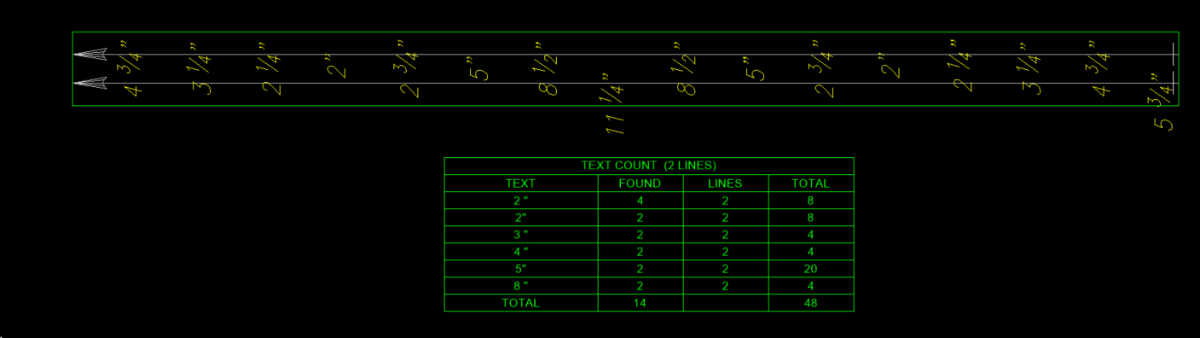
I used parts of the AI code and parts of my code that I had, like correct counts and correct table output to match task. Big thanks @Least I will look at Claude a lot more. https://forums.autodesk.com/t5/visual-lisp-autolisp-and-general/need-help-counting-support-quantities-can-you-please-help/td-p/14238558/page/3
-
 kim1022 joined the community
 -

Free Browser-Based STEP/STP Viewer for Quick CAD Inspection
cadprops replied to cadprops's topic in AutoCAD 3D Modelling & Rendering
Thanks for the detailed feedback! I’ve just improved the .3mf handling and fixed several compatibility issues. Could you give those files another try when you have a chance? If any of them still fail to open, I’d really appreciate it if you could let me know. Thanks again for helping me improve CADProps! -
Free Browser-Based STEP/STP Viewer for Quick CAD Inspection
cadprops replied to cadprops's topic in AutoCAD 3D Modelling & Rendering
Thanks for the detailed feedback! I’ve just improved the .3mf handling and fixed several compatibility issues. Could you give those files another try when you have a chance? If any of them still fail to open, I’d really appreciate it if you could let me know. Thanks again for helping me improve CADProps! - Last week
-
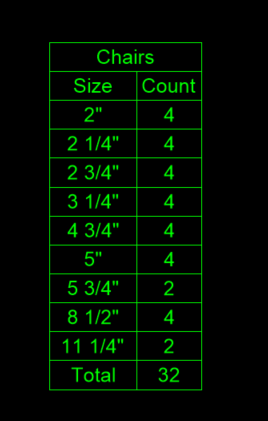
I am impressed with the result its very close, has a couple of things to fix. The Mtext needs to keep the Fraction text. It also needs to sort on that fraction text. If you look at image correct answer is Total = 32. One issue of the dwg is may need to get end user to make sure text is within a reasonable offset from the plines etc, In true dwg some ends are at angles and end text is close. But will test more. One thing I did not mention is there is 13 separate multi line segments to get the total for say a total maybe 1000+ but don't worry about that for now. I consider wether to keep going with what I have oe use what has been provided. Attached a sample dwg. Test lines text.dwg
-
VS Code + AutoCAD Lisp Extension Issues (Need constant re-starts)
DavidP replied to DavidP's topic in AutoLISP, Visual LISP & DCL
I may have been using vs Code incorrectly.... Before I was just loading the lisp or lisp(s) files I thought I need to test a specific function... but now I'm loading all the lisp in project before I start debugging... this change in approach appears to work much better. So for each Project I create a lisp called main.lsp the main function of this is to read the vscode project prj file and load each Lisp in the project while reporting the load status. (I hardcore file path and file name : I attach vs code while in the main function and run the main while checking to ensure none failed to load... then just debug as normal... So far I haven't had to do a restart yet. So now every time I make a code change I run main first then call what ever function I need to debug. (defun c:main ( / path projectfile ProjectLispList fileName filePath result) (setq path "C:/Tools/Projects/Project1/") (setq projectfile "MyProject.prj") (setq ProjectLispList (ReadProjectFile (strcat path projectfile))) (foreach fileName ProjectLispList (if (or (vl-string-search "\\" fileName) (vl-string-search "/" fileName) (vl-string-search ":" fileName)) (setq filePath fileName) (setq filePath (strcat path fileName ".lsp")) ) (if (findfile filePath) (progn (setq result (vl-catch-all-apply 'load (list filePath))) (if (vl-catch-all-error-p result) (princ (strcat "\nFAILED: " filePath)) (princ (strcat "\nSUCCESS: " filePath)) ) ) (princ (strcat "\nNOT FOUND: " filePath)) ) ) (princ) ) (defun ReadProjectFile (filePath / file line trimLine inList names start end name) (setq file (open filePath "r")) (setq inList nil) (setq names nil) (if file (progn (while (setq line (read-line file)) (setq trimLine (vl-string-trim " " line)) (if (= (strcase trimLine) ":OWN-LIST") (setq inList T) (if inList (if (= trimLine ")") (setq inList nil) (progn (if (= (substr trimLine 1 1) "(") (setq trimLine (substr trimLine 2)) ) (if (= (substr trimLine 1 1) "\"") (progn (setq start (vl-string-search "\"" trimLine)) (setq end (vl-string-search "\"" trimLine (1+ start))) (setq name (substr trimLine (+ start 2) (- end start 1))) (setq names (append names (list name))) ) ) ) ) ) ) ) (close file) ) ) (reverse names) )