All Activity
- Past hour
-

Help to Modify Existing Line Annotation LISP
SLW210 replied to KraZeyMike's topic in AutoLISP, Visual LISP & DCL
If it helps, @dlanorh has other versions that are similar some have comments to make alterations. Here is one BAD. And this VLAB. Here is the ORIGINAL of BAD4. - Today
-
If you know how to use AI it can be beneficial, I just wonder what adverse effects the unlearned masses are having on the future results. Lately on social media, forums etc. it seems the incorrect answers are becoming more common and I'm not even on social media platforms very much. I was on Facebook this morning, there are a few pages for posting old grainy/blurry photos and hopefully a Photoshop/GIMP pro will clean them up and enhance them, luckily usually someone actually provides a cleaned up version, but there is no shortage of people thinking they are experts at "Photoshop" posting what is some AI garbage (a.k.a. Photoslop). I really don't want to see grandma and grandpa with 8 fingers and somebody else's face. Most get called out, but it is becoming prolific. Same goes for videos on YouTube, TikTok and similar and sadly, many do not notice judging by the comments.
-
Reload LineTypes in AutoCAD 2027 not working?
SLW210 replied to Aftertouch's topic in The CUI, Hatches, Linetypes, Scripts & Macros
Any follow up from Autodesk? I am about to start working on some linetypes, some with shapes. I'll see about an upgrade to 2027 and hopefully they put out a fix for this. -
VS Code + AutoCAD Lisp Extension Issues (Need constant re-starts)
SLW210 replied to DavidP's topic in AutoLISP, Visual LISP & DCL
Are you working at a company or from home? I know I have problems with Powershell and VS Code at work, since for some reason they have it somewhat blocked for some things needed by VS Code. Though I do not remember having this exact issue. -
Can you post an actual drawing with before and after and any other options? Have you tried using a Multileader?
-
 agurwidi joined the community
 -
 harshkhatri joined the community
 -
 cha joined the community
 - Yesterday
-
Alright, folks. It’s pop quiz time. I’ll even make it multiple choice. Q. What do you call the interface item that moves with your mouse and has vertical and horizontal lines with a little box in the middle? A. Crosshair B. Cursor C. Both D. Neither The answer, dear reader, is C. Both. Like a few other things in AutoCAD, this element is named differently depending on where you look. Did you know you could customize it to your personal preference? Like most things in AutoCAD, you absolutely can. Some are more common than others, so I’ll group them that way, as I present them to you (in no particular order, other than the groups). AutoCAD Crosshair Size Probably the most common change is the size. This is most easily found in the Display tab of the Options dialog. There, you’ll find a text box and slider to define the size to display as a percentage of the screen size. Notice that here, and in the tooltip, this UI element is called Crosshairs, all while telling us via the tooltip that you’re setting the CURSORSIZE variable. Hmm. Anyway, by default it is set to 5, or 5% of the screen. Some people like it bigger. You do you. Valid settings go from 1 to 100, with 100 showing the Cursor as full screen. Next up is the little box in the middle, as I so eloquently described it earlier. This is controlled by the PICKBOX system variable, or you can use the handy slide control as found under the Selection tab of the Options dialog. Its default is 3, and valid settings can be from 0 to 50. When set to zero, selection previewing of objects is not available. AutoCAD Aperture Next is Aperture, which isn’t really a visual part of the crosshair, but it does affect how it works. You know that invisible area that defines when AutoCAD detects and locks onto objects when Object Snap (OSNAP) modes are active? Well, that’s the Aperture. The default is 10, which is larger than the Pickbox, so if you change the Pickbox size, I suggest bumping up the Aperture by a similar ratio. You can set it from a handy slider control in the Drafting tab of the Options dialog. Its system variable name is APERTURE, so you can just type that in also. Valid settings are 1 to 50. AutoCAD Crosshair Color Finally, we come to the crosshair’s color. Change it to whatever floats your boat by clicking on the Colors button in the Display tab of the Options dialog. Choose Crosshairs from the elements list and use the color pulldown to suit your current mood, or maybe your favorite sports team. It’s up to you. Or you could be like me, and leave it to its default. It’s your choice. Uncommon Changes You know those little glyphs that show up next to your crosshair or pickbox that indicate what editing command you’re using? Those are called Badges, and you can control whether you see them or not. Below is an image showing the Erase badge. There is no GUI control for these, so you’ll have to remember the system variable, CURSORBADGE. Set it to 1 to turn them off, or leave it at its default value of 2 to turn them on. This next one flies under the radar, as I’ve never come up with a single good reason to use it, except to prank one of your co-workers (which is not condoned by anyone here at Tuesday Tip HQ). It’s called CURSORTYPE, and again, it’s nowhere to be found in the GUI, so you’ll have to type it in. If you do, you can set it to 1, which will change the normal AutoCAD crosshair into a Microsoft Windows® mouse pointer. Now you know. Recall in the opening quiz, I described the cursor/crosshair as being vertical and horizontal lines? Well, they don’t have to be. There are a couple of ways to change that. One is another system variable called SNAPANG, which rotates the crosshair for you to a specified angle. In the image below, I’ve set SNAPANG to 25, which is the angle that the line is drawn. With ORTHO turned on, it’s a great way to draw at the same angle as your objects. The other rotation mechanism is, of course, the ISODRAFT command. Your easiest method will be to turn it on from the Status Bar. The icon has a menu associated with it, which will allow you to change the drawing plane that you need. Do you like keyboard shortcuts as I do? Use CTRL-E to cycle through Top, Left, or Right planes. One last thought Remember that tease about the other function with different names? You probably know it as PUBLISH. Well, as an old sportscaster was fond of saying, “not so fast, my friends.” If you go to the pulldown menu for the Quick Action Toolbar (QAT), you’ll find one of the possible entries is Batch Plot. You’ll find it named that way in the Plot flyout menu of the Application Menu (the big A in the corner). Go figure… More Tuesday Tips Check out our whole Tuesday Tips series for ideas on how to make AutoCAD work for you. The post AutoCAD Crosshair: Tuesday Tips With Frank appeared first on AutoCAD Blog. View the full article
-
Alright, folks. It’s pop quiz time. I’ll even make it multiple choice. Q. What do you call the interface item that moves with your mouse and has vertical and horizontal lines with a little box in the middle? A. Crosshair B. Cursor C. Both D. Neither The answer, dear reader, is C. Both. Like a few other things in AutoCAD, this element is named differently depending on where you look. Did you know you could customize it to your personal preference? Like most things in AutoCAD, you absolutely can. Some are more common than others, so I’ll group them that way, as I present them to you (in no particular order, other than the groups). AutoCAD Crosshair Size Probably the most common change is the size. This is most easily found in the Display tab of the Options dialog. There, you’ll find a text box and slider to define the size to display as a percentage of the screen size. Notice that here, and in the tooltip, this UI element is called Crosshairs, all while telling us via the tooltip that you’re setting the CURSORSIZE variable. Hmm. Anyway, by default it is set to 5, or 5% of the screen. Some people like it bigger. You do you. Valid settings go from 1 to 100, with 100 showing the Cursor as full screen. Next up is the little box in the middle, as I so eloquently described it earlier. This is controlled by the PICKBOX system variable, or you can use the handy slide control as found under the Selection tab of the Options dialog. Its default is 3, and valid settings can be from 0 to 50. When set to zero, selection previewing of objects is not available. AutoCAD Aperture Next is Aperture, which isn’t really a visual part of the crosshair, but it does affect how it works. You know that invisible area that defines when AutoCAD detects and locks onto objects when Object Snap (OSNAP) modes are active? Well, that’s the Aperture. The default is 10, which is larger than the Pickbox, so if you change the Pickbox size, I suggest bumping up the Aperture by a similar ratio. You can set it from a handy slider control in the Drafting tab of the Options dialog. Its system variable name is APERTURE, so you can just type that in also. Valid settings are 1 to 50. AutoCAD Crosshair Color Finally, we come to the crosshair’s color. Change it to whatever floats your boat by clicking on the Colors button in the Display tab of the Options dialog. Choose Crosshairs from the elements list and use the color pulldown to suit your current mood, or maybe your favorite sports team. It’s up to you. Or you could be like me, and leave it to its default. It’s your choice. Uncommon Changes You know those little glyphs that show up next to your crosshair or pickbox that indicate what editing command you’re using? Those are called Badges, and you can control whether you see them or not. Below is an image showing the Erase badge. There is no GUI control for these, so you’ll have to remember the system variable, CURSORBADGE. Set it to 1 to turn them off, or leave it at its default value of 2 to turn them on. This next one flies under the radar, as I’ve never come up with a single good reason to use it, except to prank one of your co-workers (which is not condoned by anyone here at Tuesday Tip HQ). It’s called CURSORTYPE, and again, it’s nowhere to be found in the GUI, so you’ll have to type it in. If you do, you can set it to 1, which will change the normal AutoCAD crosshair into a Microsoft Windows mouse pointer. Now you know. Recall in the opening quiz, I described the cursor/crosshair as being vertical and horizontal lines? Well, they don’t have to be. There are a couple of ways to change that. One is another system variable called SNAPANG, which rotates the crosshair for you to a specified angle. In the image below, I’ve set SNAPANG to 25, which is the angle that the line is drawn. With ORTHO turned on, it’s a great way to draw at the same angle as your objects. The other rotation mechanism is, of course, the ISODRAFT command. Your easiest method will be to turn it on from the Status Bar. The icon has a menu associated with it, which will allow you to change the drawing plane that you need. Do you like keyboard shortcuts as I do? Use CTRL-E to cycle through Top, Left, or Right planes. One last thought Remember that tease about the other function with different names? You probably know it as PUBLISH. Well, as an old sportscaster was fond of saying, “not so fast, my friends.” If you go to the pulldown menu for the Quick Action Toolbar (QAT), you’ll find one of the possible entries is Batch Plot. You’ll find it named that way in the Plot flyout menu of the Application Menu (the big A in the corner). Go figure… More Tuesday Tips Check out our whole Tuesday Tips series for ideas on how to make AutoCAD work for you. The post AutoCAD Crosshair: Tuesday Tips With Frank appeared first on AutoCAD Blog. View the full article
- Last week
-

Python, Clone Layout from another drawing
CyberAngel replied to Danielm103's topic in .NET, ObjectARX & VBA
I did not know Python worked with AutoCAD. Well done, sir- 1 reply
-
- 1
-

-
 marsbimsolutions joined the community
 -
 Saifulhaq_kkk joined the community
 -
 Avi Global Plast joined the community
 -
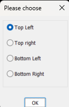
If your using a dynamic block you will need to make 4 visibility states with each visibility state having a correct connecting line. I can give you a choose location method, I use BRICSCAD so I will not make a block as it does dynamic blocks slightly different. Ok so need a lisp that you pick a point for block and then visibility is asked for and values. The connecting line will have a anchor point but the block can be moved and the line stretched.

-
 emekaude joined the community
 -
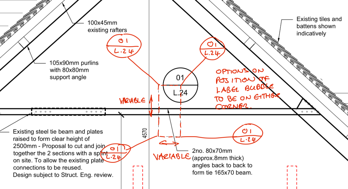
We use the title block and marker block to highlight details on a Plot File sheet and then to label the corresponding detail on a subsequent page. The problem I want to resolve is how to make the bubble with the detail number and page number in it independent and move separately to the dashed box. Ideally, the detail marker box is adjustable in height and width to suit the size of the detail, and then a line between the two, which will stay fixed to the top corner, although if this could move to any corner that would be good. The movable distance of the bubble to be variable and for it all to be annotative........?! We have tried editing it in the block editor and adding a point parameter and a move action, with stretch etc, but have got totally lost and made it worse than it started. Any help greatly appreciated. I did look for similar posts, but couldn't see anything that covered this specifically. Apologies if we have missed it. Look forward to hearing from you brains soon!! Detail Marker.dwg
-
VS Code + AutoCAD Lisp Extension Issues (Need constant re-starts)
SLW210 replied to DavidP's topic in AutoLISP, Visual LISP & DCL
If still interested in VS Code, perhaps a read through To Setup the AutoCAD AutoLISP Extension for Debug (AutoLISP/VS Code) | Autodesk. I have seen other errors resolved by uninstalling and reinstalling the Extension and/or VS Code. Installing Visual Studio Code on Windows - Earlier
-

VS Code + AutoCAD Lisp Extension Issues (Need constant re-starts)
mhupp replied to DavidP's topic in AutoLISP, Visual LISP & DCL
here are some tips. https://lee-mac.com/debugvlide.html -Edit Might have to set LISPSYS Back to 1 to use VS code again. -

VS Code + AutoCAD Lisp Extension Issues (Need constant re-starts)
DavidP replied to DavidP's topic in AutoLISP, Visual LISP & DCL
I never use it but perhaps I should give a try instead thanks. -
VS Code + AutoCAD Lisp Extension Issues (Need constant re-starts)
DavidP replied to DavidP's topic in AutoLISP, Visual LISP & DCL
Thanks for the link, just notice the documentation it says I run vscode as admin ('ll try that and see and improvement). (my user has admin privileges but I never actually force VS Code to start with admin privileges ). I'll try that and see it improves. I believe the setup is fine as I can do both debug attach or debug launch... Also the executable for AutoCAD map is acad.exe just as AutoCAD. The behavior I see is as if VSCode loses contact with ACAD or as if it never releases the processes. At times it prompts me if I want to start a 2nd Debug Attach. I may go a day where I only need to restart once or twice other times I'm forced to restart 20 to 30 times. I wonder if could be interference with some other plug ins like ArcgIS. -
VS Code + AutoCAD Lisp Extension Issues (Need constant re-starts)
mhupp replied to DavidP's topic in AutoLISP, Visual LISP & DCL
I think you can still use VLIDE. if If VLIDE Doesn't Open set LISPSYS to 0 Tho doesn't have autocomplete and color coding like vs code. -
VS Code + AutoCAD Lisp Extension Issues (Need constant re-starts)
SLW210 replied to DavidP's topic in AutoLISP, Visual LISP & DCL
Did you read the instructions for the AutoCAD AutoLISP extension? I run code with AutoCAD, which is the path you show using, that probably doesn't work with AutoCAD Map3D, so you might need to repath if that's the program you use or just use AutoCAD and see if that resolves the issue. From AutoCAD AutoLISP Extension - Visual Studio Marketplace -
VS Code + AutoCAD Lisp Extension Issues (Need constant re-starts)
DavidP posted a topic in AutoLISP, Visual LISP & DCL
I have this Issue with in VSCode where I'm forced to constantly restart both applications in order to continue debugging. My Setup: AutoCAD Map3d 2021 VS Code 1.27.0 + Autocad AutoLISP Extension 1.6.3 VSCode Extitions Setup: Process name = acad AutoCAD com…start switchs: C:\Program Files\Autodesk\AutoCAD 2021\acad.exe Absolute path: C:\Program Files\Autodesk\AutoCAD 2021\acad.exe I start Autocad First, then run vlide from the command prompt to load the the VScode application. Then typical open a lisp project containing multiple lisp files. Then to start debugging by Pressing “F5”. Some times this works fine but more often than not I need to restart both app multiple times.. This happens mostly after I run into a code error… like typo or syntax error or trying to load a file autocad cant find. The only way to be able to continue debugging my project is to completely restart both vscode and autocad(once or a few times). I seen this with my previous setup as well (different hardware, os and applications versions). Any idea or suggestion why this could be happening? -

How to create field that shows text from a dimension
BIGAL replied to ColinPearson's topic in AutoCAD 2D Drafting, Object Properties & Interface
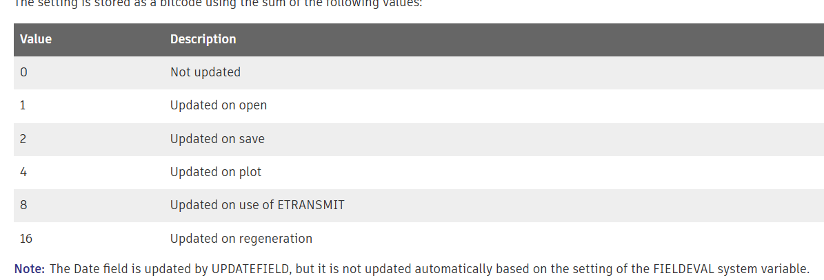
Went away and had a look at why 31. Sum the values.
-

How to create field that shows text from a dimension
ColinPearson replied to ColinPearson's topic in AutoCAD 2D Drafting, Object Properties & Interface
@zaphod That's a good one, thank you! -

How to create field that shows text from a dimension
zaphod replied to ColinPearson's topic in AutoCAD 2D Drafting, Object Properties & Interface
the system/drawing variable "fieldeval" is set to 4, it needs to be set to 31 in order to visibly see it update. Drawing2.dwg -
Reload LineTypes in AutoCAD 2027 not working?
SLW210 replied to Aftertouch's topic in The CUI, Hatches, Linetypes, Scripts & Macros
I can't remember what I ended up doing. My issue was very similar and involved linetypes with shape files. Please post back here if Autodesk resolves the issue. -

Reload LineTypes in AutoCAD 2027 not working?
Aftertouch replied to Aftertouch's topic in The CUI, Hatches, Linetypes, Scripts & Macros
I got myself a workaround that seems to work for me. Made a LISP (long live AI) that stores all layer and linetype combinations. Sets everything to 'Continious', purges all linetypes, that reloads the linetypes and that restores the default settings. This seems to do the trick to get rid off all 'corrupted' linetype definitions, and 'reloading' is replaced with a load function. -
Change text color in AutoCAD Lt Tables Lisp request
BIGAL replied to MSHR's topic in AutoLISP, Visual LISP & DCL
You need to post a true copy of what ever your starting with as you hinted a csv or a pdf. There is nom problem reading a csv and inserting all the borehole blocks at correct location, yes can look at other details so can insert different blocks when required, That is the sort of information you are not providing. eg a csv file like this. I can see need to compare your look up table that you previously provided. Once this sort of information is posted then a complete solution can be provided. Not just questions. Bore 1 X,Y 0.5,Green dirt 1.2,Black dirt 2.4,Blue dirt Bore 2 X,Y 1.3,Green Dirt 2.2,Black dirt Bore 3 and so on -
Reload LineTypes in AutoCAD 2027 not working?
SLW210 replied to Aftertouch's topic in The CUI, Hatches, Linetypes, Scripts & Macros
@Aftertouch I thought this may be a bug. I think there may be other bugs since 2025 version, I had some issues last year with linetypes. I'll play around with it next week when I am at work and have AutoCAD 2026 to test. @tombu I have the other one in that thread from Cad Studio, I'll have to try yours out when I get to work next week. -
Reload LineTypes in AutoCAD 2027 not working?
BIGAL replied to Aftertouch's topic in The CUI, Hatches, Linetypes, Scripts & Macros
Did the reload shx work ? It may take some time for a bug fix.