All Activity
- Today
-
I have it working on blocks that are dimensioned in the same space and curve objects in modelspace that are dimensioned in paperspace through a Viewport, but not blocks in modelspace dimensioned in paperspace through a Viewport, so a little more thinking. I also plan to keep the Fallback Crosshair option for older AutoCAD and any other CAD that doesn't have CENTERMARK command.
-
I've been developing CADstart, a browser-based 2D CAD learning platform, so I appreciate what you're trying to accomplish. I like the idea of helping beginners practice through challenges. One thing I'd be interested in is how you're introducing precision, object snaps, and dimensions before students move into more complicated exercises. Wishing you success with the project.
-

Finding overlapping geometry without manually checking every line
CADhomie replied to indiancad's topic in AutoCAD 2D Drafting, Object Properties & Interface
I work with 2D CAD drawings for protective foam packaging and CNC, so overlapping geometry is something I pay attention to. Duplicate lines can create problems downstream, especially when preparing closed profiles for cutting. I think it's worth teaching beginners to check their geometry early instead of waiting until export. -
CADhomie joined the community
-
Fillet or blend between two non-parallel cylinders
lrm replied to Dale Grice's topic in AutoCAD 3D Modelling & Rendering
@indiancad The cylinders do not intersect. In addition, depending on the magnitude of the fillet radius, the fillet may need to be tangent to a cylindrical surface and a flat plane for a portion of its extent. I don't think filletedge or blend has much potential in this case. Try it out yourself. -

Finding overlapping geometry without manually checking every line
SLW210 replied to indiancad's topic in AutoCAD 2D Drafting, Object Properties & Interface
That depends on the LISP. Check my GETLEN.lsp. as an example. A new get length LISP - AutoLISP, Visual LISP & DCL - AutoCAD Forums It gets perimeters and accounts for gaps and overlaps even in anonymous blocks. I made that due to SOLPROF profiles being a pain with the overlaps, etc.. So, sometimes a cleanup isn't required to get correct information, just a LISP or other code. I have one somewhere, but there are a few online "OVERKILL" type LISPs that work on blocks and sometimes better cleanup, something OVERKILL doesn't do all of the time. But, OVERKILL does under normal circumstances do fairly well, so a first run with that, or a second run if the drawing needs a real flattening, best to do that first. The waterjet/plasma cutter person at work does a lot of the work for those machines now, but I used to do all of it when those were first purchased. So I have done lots of cleanups for cutting. Luckily, most things I start are pretty clean except the SOLPROF and SOLVIEW/SOLDRAW objects. The software that came with the waterjet also can do some cleaning. So I have that as well. -

Aluminum composite panels parametric templates
emosms replied to emosms's topic in AutoCAD 2D Drafting, Object Properties & Interface
dont quite get what u do (also the video above). Is that Bricks Cad and DCL (data control language) used in bricks cad? -

Fillet or blend between two non-parallel cylinders
indiancad replied to Dale Grice's topic in AutoCAD 3D Modelling & Rendering
If both cylinders are 3D solids and intersect, try FILLETEDGE on the intersection edge. If you need a smooth transition between separate cylindrical surfaces, BLEND may be more suitable. -
 Nam Le joined the community
-
Finding overlapping geometry without manually checking every line
indiancad replied to indiancad's topic in AutoCAD 2D Drafting, Object Properties & Interface
That's a useful approach. Do your LISP routines also detect partially overlapping lines, or mainly exact duplicates? - Yesterday
-
 OSM2CDR joined the community
-
Fillet or blend between two non-parallel cylinders
lrm replied to Dale Grice's topic in AutoCAD 3D Modelling & Rendering
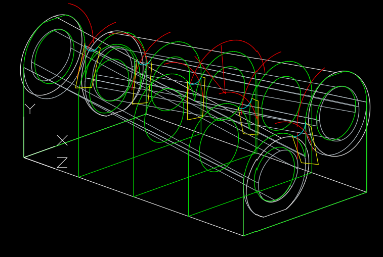
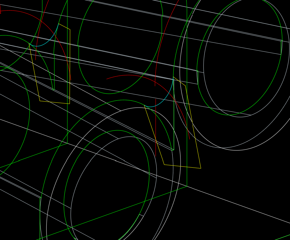
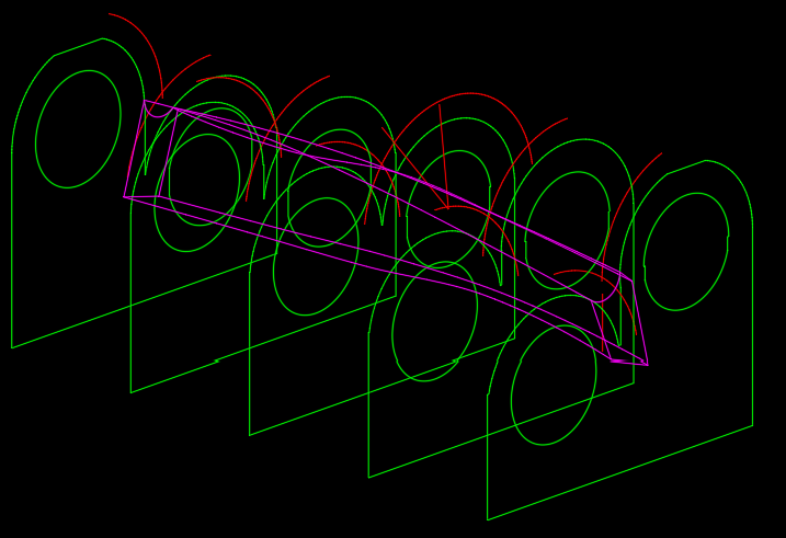
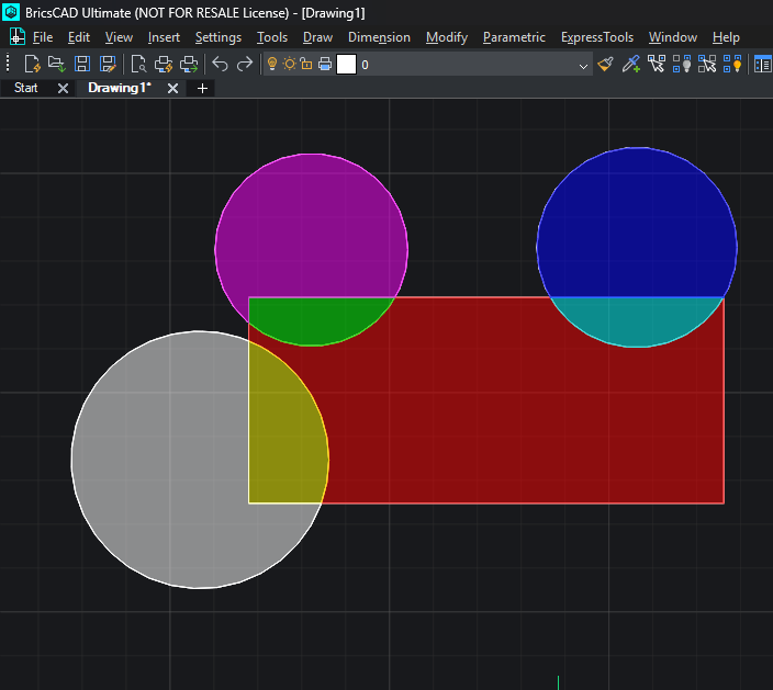
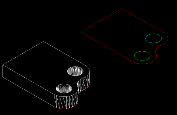
Create sections (green) at several points along the object. Explode the sections then set a UCS to the plane of a section and create offset curves (red) with a distance equal to the desired fillet radius. I used 0.2. Add a circle of the fillet radus at the intersection of the offset curves and then trim the circle. Create a polyline (yelllow) to form a closed shape that includes the "fillet" arc (cyan). With pedit create closed polylines for the fillet sections then use loft to create the fillet solid. Union the two solids together.
-
[Free LISP] Auto-mark revision clouds for design changes — compare two regions in same DWG
SLW210 replied to Beastt1992's topic in AutoLISP, Visual LISP & DCL
I got to thinking about this and with some other LISPs it would be handy for my use to check if anyone has been altering a drawing on the network without permission. I normally look at the last saved time and date, but something like this might be useful to see what if anything was physically altered. -
Fillet or blend between two non-parallel cylinders
SLW210 replied to Dale Grice's topic in AutoCAD 3D Modelling & Rendering
The two tubes run at different angles. -
Fillet or blend between two non-parallel cylinders
SLW210 replied to Dale Grice's topic in AutoCAD 3D Modelling & Rendering
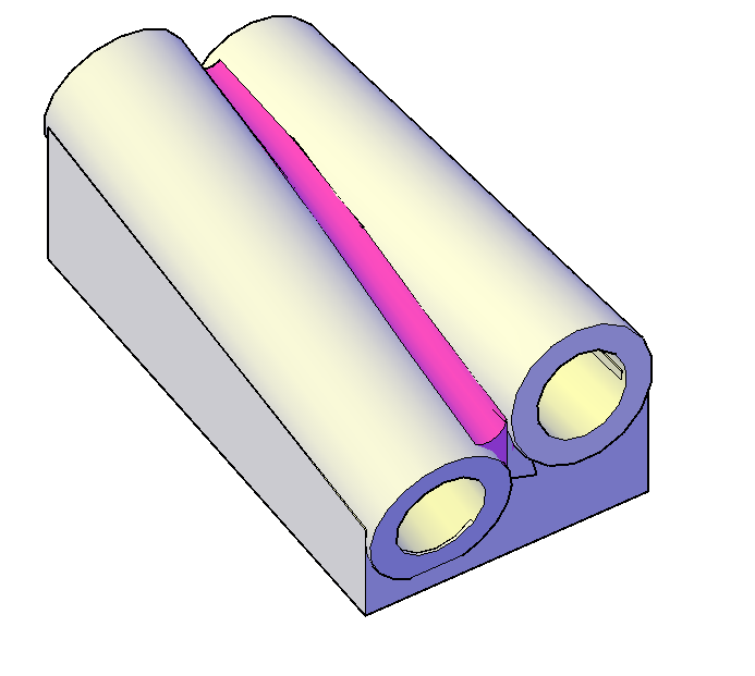
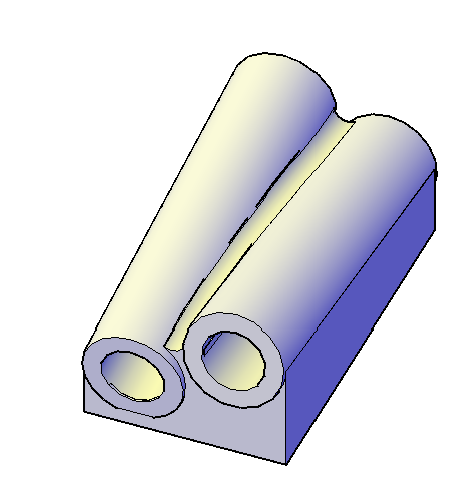
I gave the drawing a look. I am not 100% sure what you are trying to accomplish here, in order to fillet the two cylinders they need to share a common edge(s), the rectangular extrusion you have between them needs to be unioned as far as I know, if that's what you are trying to use, by the way it looks to be two of those. You might have better luck extruding a fillet shape between them and then union that to them. -
Finding overlapping geometry without manually checking every line
SLW210 replied to indiancad's topic in AutoCAD 2D Drafting, Object Properties & Interface
I use a couple of LISPs. -

create transparent hatch with Python
Danielm103 replied to Danielm103's topic in .NET, ObjectARX & VBA
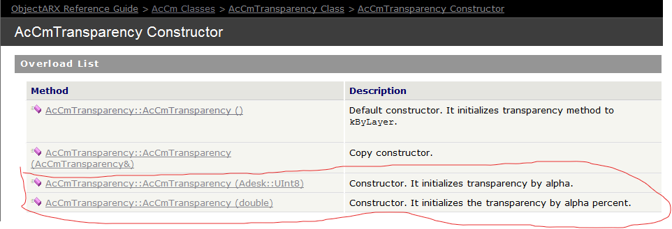
Db.Transparency in ARX (and Python) is overloaded to take an alpha 0-255 or alphaPercent 0.0 – 1.0, so you can use either. 0.5 is the same as 127 in this case. In this case traceBoundary was called with detect islands = False. Of course one might like to have a different transparency between the boundary and hatch, this just illustrates one
-
create transparent hatch with Python
indiancad replied to Danielm103's topic in .NET, ObjectARX & VBA
The key is to make the Hatch entity itself see-through not the boundary lines that get drawn. The hatch must also be checked after each boundary loop is added. The main fix is the transparency value. For 50% see‑through use an alpha value 127 instead of 0.5 because Db.Transparency uses a 0–255 scale. Set it directly on the hatch for example: hat.setTransparency(Db.Transparency(127)). Also if traceBoundary returns loops find the outer loop and any inner islands separately before you call appendLoop. If you do not do this the hatch might fill spots that should stay open. - Last week
-
 Justadisplayname joined the community
-
import traceback from pyrx import Ap, Db, Ed, Ge _index = 1 def makeBoundary(db: Db.Database, pnt: Ge.Point3d, tr: Db.Transparency): ids = [] plines = Ed.Editor.traceBoundary(pnt, False) for pline in plines: pline.setColorIndex(_index) # Uses the global integer pline.setTransparency(tr) ids.append(db.addToModelspace(pline)) return ids @Ap.Command() def doit(): global _index try: db = Db.curDb() tr = Db.Transparency(0.5) #50% ps, pnt = Ed.Editor.getPoint("\nSelect internal point: ") if ps != Ed.PromptStatus.eOk: return # 1. Generate the boundary polylines ids = makeBoundary(db, pnt, tr) if not ids: print("\nNo boundary found.") return # 2. Create and configure the Hatch object hat = Db.Hatch() hat.setPattern(Db.HatchPatternType.kPreDefined, "SOLID") hat.setColorIndex(_index) hat.setTransparency(tr) # 3. Add hatch to model space BEFORE appending loops (AutoCAD requirement) db.addToModelspace(hat) # 4. Establish associativity and evaluate hat.setAssociative(True) hat.appendLoop(Db.HatchLoopType.kDefault, ids) hat.evaluateHatch(True) print(f"\nCreated boundary and hatch with Color Index: {_index}") # 5. Increment color index (Cycle back to 1 if it exceeds standard ACI 255) _index += 1 if _index > 255: _index = 1 except Exception as e: print("Error encountered:") traceback.print_exc()
-

Fillet or blend between two non-parallel cylinders
Dale Grice replied to Dale Grice's topic in AutoCAD 3D Modelling & Rendering
Hi, Drawing attached. Dale CB&Q water tower hoop lugs v2.dwg -
 niloo_ch joined the community
-

Fillet or blend between two non-parallel cylinders
BIGAL replied to Dale Grice's topic in AutoCAD 3D Modelling & Rendering
Going back a few steps looking at your image if you were to draw the two outside circles in 2D, you can add a fillet arc using Circle TTR you need to trim the new circle and trim the existing two circles add the outer edges and so on add the inner tube circles then extrude the outside object as a pline. There may be some way to add the correct fillet to a solid beyond my pay grade some one else will jump in.
-
Fillet or blend between two non-parallel cylinders
SLW210 replied to Dale Grice's topic in AutoCAD 3D Modelling & Rendering
Welcome to CADTutor! Can you post the .dwg? -
Fillet or blend between two non-parallel cylinders
Dale Grice posted a topic in AutoCAD 3D Modelling & Rendering
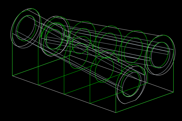
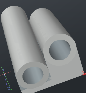
Hi all, I have been struggling or having a senior moment with getting a fillet between these two cylinders. Like rubbing a bead of caulk with your finger between them. Any suggestions? Thanks, Dale
-
Dale Grice joined the community
-
 Arthur 09 joined the community
-
Best Way to Protect Commercial AutoLISP Applications – High-Level Security and Licensing
indiancad replied to Sathar's topic in AutoLISP, Visual LISP & DCL
For commercial AutoLISP applications I would not trust FAS VLX compilation alone. It makes looking at the source code but it should not be seen as full protection from people trying to figure out how it works. A better way is to put parts about licenses and checks into a compiled.NET component. Use a server to check licenses and connect activations to a mix of computer details. I also suggest using signed license answers storing information in a way on the computer checking online now and then and allowing a short time without internet. Do not depend on hardware IDs because changes in hardware can cause real problems with activation. One key thing to remember: no protection on the computer side is completely safe. The aim is to make it hard for people to copy and change the software while making sure real users can activate and renew easily. It would be interesting to find out if people here have done this with their licensing server or, with a company that offers licensing services. -
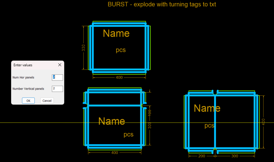
When working with drawings received from other companies, you may encounter blocks containing attributes such as part numbers, descriptions, or reference labels. If you need to convert those blocks into ordinary drawing entities while preserving the displayed attribute values, the BURST command can be useful. Unlike EXPLODE, it converts attribute values into text rather than simply losing them. However, converting blocks can affect the original structure and editability of the drawing. When preparing external drawings for modification or data extraction, do you prefer BURST, EXPLODE, or keeping the original attributed blocks intact? What determines your choice?
-
Finding overlapping geometry without manually checking every line
indiancad posted a topic in AutoCAD 2D Drafting, Object Properties & Interface
In a complex 2D drawing, two or more lines may occupy exactly the same position. The drawing can look perfectly correct, but duplicate geometry can cause problems during area calculations, hatching, CNC preparation, and file conversion. One useful command is OVERKILL. It detects and removes duplicate or overlapping geometry, with options to control how objects are compared. However, running it with default settings may not always produce the desired result, especially in drawings with different layers, linetypes, or partially overlapping segments. Do you routinely run OVERKILL before issuing a drawing, or do you prefer to identify and correct overlapping geometry manually? Have you ever found a problem caused by duplicate entities? -
Aluminum composite panels parametric templates
BIGAL replied to emosms's topic in AutoCAD 2D Drafting, Object Properties & Interface
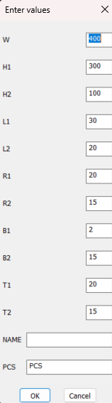
In the draw window it's for multi story buildings so size can be different for every window. There is not a problem matching properties with a dcl. You can make better descriptions, in the code is default values you set or it can remember previous values. Just have the tools to make the dcl. If you look at the window DCL in movie on right side is edge controls these do just that a corner or a multi panel join and so on. So in your comments you talk a bit about this. Yes it's drawn via objects Plines etc. You can have shapes like the V notch. The dimensioning is just part of a program. I believe it will be easier than trying to make a dynamic block work. Given how much post time has occurred in this forum, a program would be done by now. But it is for your company only so a cost may be relevant. But you can add more shapes quickly. Will see if can find time to do some form of example. Step 1
-
These are ones I use: To record the current zoom: (setq currentzoom (list (getvar 'viewctr) (getvar 'viewsize))) .. zoom as you want And this returns you to where you were. (vla-ZoomCenter (vlax-get-acad-object) (vlax-3d-point (car currentzoom)) (cadr currentzoom)) Never tried with viewports but some ssget types need the entities to be selected to be in view, maybe viewports are the same