All Activity
- Past hour
-

SHELL command to start a program
Discus84 posted a topic in AutoCAD 2D Drafting, Object Properties & Interface
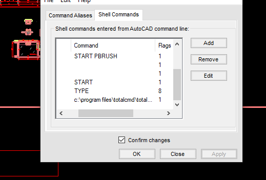
Hi, After editing the shell comamands with aliasedit I only get a blank window that popups and immediately dissapears. Notepad works as expected. I would like to run a different program.
-
Hi, I'm using PURGE and OVERKILL to clean up. Any other options?
-
Line scaling settings
Discus84 replied to Discus84's topic in AutoCAD 2D Drafting, Object Properties & Interface
I set it to and now they scale properly, which is opposite of what should be? Anyways it works, thanks! -
Confused by scale issue when set to 1:1_1
Bob658 replied to Bob658's topic in AutoCAD 2D Drafting, Object Properties & Interface
It's not a duplicate scale. As far as I'm aware 1:1_1 is a standard scale and generally that's the only one I use. - Today
-

Stretch to a point
CyberAngel replied to Discus84's topic in AutoCAD 2D Drafting, Object Properties & Interface
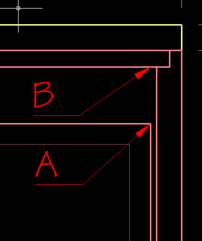
The shortcut for From is _fro. You can use fro as well, but that seems to disable all the other snaps you have. Here's a page with a list of all the snap shortcuts. -
Confused by scale issue when set to 1:1_1
CyberAngel replied to Bob658's topic in AutoCAD 2D Drafting, Object Properties & Interface
How is "1:1_1" different from "1:1"? Is it possible there's a duplicate scale? -

quick xyz coordinates text placed from selected points
pavanetc replied to pavanetc's topic in AutoLISP, Visual LISP & DCL
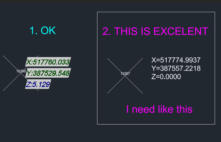
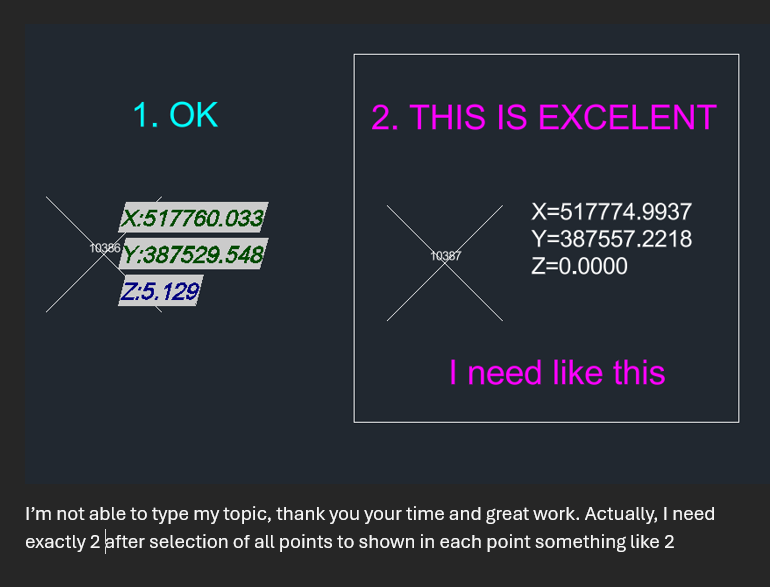
thank you your time and great work. Actually, I need exactly 2 after selection of all points to shown in each point something like 2
-
quick xyz coordinates text placed from selected points
pavanetc replied to pavanetc's topic in AutoLISP, Visual LISP & DCL
-
Confused by scale issue when set to 1:1_1
Bob658 posted a topic in AutoCAD 2D Drafting, Object Properties & Interface
I have two different models. both have the units set to metres and both have the scale set to 1:1_1. However when the 'Edit Drawing Scales' when you select the 1:1_1 it states at the bottom that '1 paper unit = 1 drawing unit' but in the other model ''1 paper unit = 0.001 drawing unit'. As you can't edit this I'm not sure how it happened. Can anybody shed any light on this.? -

Logic Issue: CENTERLINE Command Redefined with Layer Change
Clint replied to Clint's topic in AutoLISP, Visual LISP & DCL
mhupp, Your suggestion and generous code submission are both very well received: Thank you! I will rework the "robot" program code to include your superior code lines. Questions Outside of the important warning applied to LISP programming and variables, Can you or others give an example(s) of instances of how a programmer/customizer can modify default commands? Would this action be limited to creating macro code lines to assign to custom buttons? Future After stalling out, I am now at a DWG-based design environment and will resume my LISP programming studies. I was recently encouraged by understanding how to use the built-in IDE. P.S.: My thanks go out to the excellent developer and programmed systems just developed from a longtime fellow member of other forums and entrepreneur running https://cadprograms.ca/ Thanks, Clint -
Stretch to a point
Discus84 replied to Discus84's topic in AutoCAD 2D Drafting, Object Properties & Interface
This works as expected, thanks! Is there a keyboard shortcut to use the "from" feature? Thanks ! -

Line scaling settings
SLW210 replied to Discus84's topic in AutoCAD 2D Drafting, Object Properties & Interface
Try PSLTSCALE. -
Hi, Below are snippets of model space and corresponding paper space. Dashed line does not scale in paper space, although looks ok in model . How to fix this? Thanks!
-

Dynamic block - Lookup table for visibility states - not working
Calteq replied to sketch11's topic in AutoCAD Drawing Management & Output
Hi Try the attached block copy and paste it into your drawing cheers WSDynBlkImp.dwg -
 Eshwar374927 joined the community
 -

Logic Issue: CENTERLINE Command Redefined with Layer Change
mhupp replied to Clint's topic in AutoLISP, Visual LISP & DCL
Don't write lisp command that use the same names or variables as default commands. That said looks like the default centerline command only outputs to layer 0. so you would need to change it to your layer. and pause pause to let you pick the lines. (command "_.centerline" pause pause) (if (setq e (entlast)) (entmod (subst (cons 8 "CENTERLINES") ; new layer name (assoc 8 (entget e)) ; old layer (entget e) ) ) ) - Yesterday
-

How to Change Dimension in AutoCAD: Tuesday Tips With Frank
The AutoCAD Blog posted a topic in AutoCAD Blogs
In the previous Tuesday Tips, I talked about some of the more important settings to pay attention to when creating your dimension styles. In today’s post, I’ll be talking about various methods of editing existing dimensions and how to change dimension in AutoCAD. OK, let’s set the scene. You defined the location of the dimension incorrectly, or you need to alter its appearance or placement. By far, the easiest thing to do is to use the dimension object’s editing grips. In the animation below, you’ll see how easy it is to select the dimension, make one of the definition points hot and place it into a new position. After that, I hover over a dimension line grip. You’ll see a small popup menu display where you can use the dimension as the start for a continue or baseline dimension, or you can even flip the arrow! In this case, I use the grip to pull the dimension up into the room above. Finally, hovering on the grip of the text string, will again display a popup menu with various options. Here, I choose Move with Leader to re-locate the text and draw a leader. If I had just wanted to move the text string, I would use the grip much like the prior two edits. None of that is very hard, and it’s a very efficient way to make geometric edits to your dimensions. Text Overrides With Special Characters Back to Dim Style settings for a moment. A style definition will let you put the dimension text above the dimension line, or below, but not both. How can you overcome this? The answer lies in the Text Override property of the dimension object. Below, you see a typical example of doing this. I’ve got a number of these 5’-4” dimensions and I want to add TYP below the line. Select the dimension object, and from the Properties palette, scroll down to the Text panel. At the bottom, you’ll first see the measurement in gray, so you can’t edit it (more on that in a minute). Below that is Text override. This is the field that you’ll want to edit There are two parts to the special characters you’re going to use. AutoCAD will interpret <> as the dimensioned measurement, the \X as a line break, and TYP as the text to place under the dimension line. By the way, the X here must be capitalized. Please Don’t Do the Following I just said that the Measurement property is grayed out and can’t be changed via the Properties palette. That’s great. But it can still be done. And, it’s as easy as double clicking on the text string, and typing in whatever you want. Below, I’ve done just that. The 5’-4” measurement has changed, but instead of editing the geometry and/or making sure the definition points are accurately place, the lazy drafter just edits the text and moves on. Here’s the worst part. You won’t know they’ve done it. It looks right, so you just assume that it is. I actually worked with a person who did this. Don’t be that person. Trust But Verify There’s an old Russian proverb that says, “Trust but verify.” To fix overridden dimension strings, type DIMREASSOC in either the Dynamic Input Box or the Command Line. You’ll be prompted to select objects. At this point, select an area, or just type in ALL since the command filters out anything that’s not a dimension. In other words, don’t take extra time to carefully select only dimensions – DIMREASSOC doesn’t care. Note: There is also a command called DIMREASSOCIATE – fully spelled out. It does something entirely different, so please be aware. If there are any dimensions that have overridden text, they will be immediately highlighted for you, as shown below. Here, I find that four of the 3’ dimensions are wrong. Now comes the easy part. Just hit Enter to end object selection, and Boom! All the overridden dimensions now read accurately. There you go, dear readers. Dimension settings and editing in two parts. Next time, I’ll be presenting some of the more important things you need to pay attention to with your CAD standards, and maybe even some ways to manage them. More Tuesday Tips Check out our whole Tuesday Tips series for ideas on how to make AutoCAD work for you. The post How to Change Dimension in AutoCAD: Tuesday Tips With Frank appeared first on AutoCAD Blog. View the full article -
Logic Issue: CENTERLINE Command Redefined with Layer Change
Clint posted a topic in AutoLISP, Visual LISP & DCL
Can someone review the code and pick out the error in logic? The BLADE IDE in BricsCAD shows no syntax errors: The code runs well. The defined layer for the centerline is not activating when the command is run (nor returning to the older/previous layer) There is obviously something out of order in the code logic and order. Leaning on AI to learning programming is not a valid shortcut for study and experience! Back to the books for me! Thanks! ;;; CENTERLINE.lsp - Custom CENTERLINE assigning it to the CENTERLINE layer ;;; Author: CEH Assisted by AI ;;; Created on: 2025-12-16 ;;; Last edited: 2025-12-16 ;;; Description: ;;; BricsCAD CENTERLINE command redefined: ;;; Creates centerlines on layer CENTERLINE with CENTER2 linetype, ByLayer color, and ~0.008 inch lineweight ;;; ;;; ------------------------- Program Start ------------------------- ;;; (defun c:CENTERLINE (/ oldlayer oldltype oldlw laydata) ;; Save current settings (setq oldlayer (getvar 'clayer) oldltype (getvar 'celtype) oldlw (getvar 'celweight)) ;; Ensure CENTERLINE layer exists (if (not (tblsearch "LAYER" "CENTERLINE")) (progn ;; Load CENTER2 linetype if not already loaded ;; Tries acad.lin (imperial) first, then acadiso.lin (metric) (cond ((not (tblsearch "LTYPE" "CENTER2")) (command "._-linetype" "_load" "CENTER2" "acad.lin" "") ) ((not (tblsearch "LTYPE" "CENTER2")) (command "._-linetype" "_load" "CENTER2" "acadiso.lin" "") ) ) ;; Create the layer: CENTER2 linetype, ByLayer color, ByLayer lineweight initially (command "._-layer" "_make" "CENTERLINE" "_ltype" "CENTER2" "" "_color" "bylayer" "" "_lweight" "bylayer" "") ) ;; If layer exists but linetype might not be set (progn (command "._-layer" "_set" "CENTERLINE" "_ltype" "CENTER2" "CENTERLINE" "") ) ) ;; Set current layer to CENTERLINE (setvar 'clayer "CENTERLINE") ;; Set current linetype and lineweight to ByLayer (setvar 'celtype "BYLAYER") (setvar 'celweight -1) ; -1 = ByLayer ;; Set layer lineweight to exactly 0.008 inches (converted to internal 0.01 mm units) ;; 0.008 in = 0.2032 mm → 20.32 → integer 2032 (in hundredths of mm? Wait, no: ;; DXF code 370 stores lineweight in hundredths of mm (0.01 mm units), always mm. (setq laydata (entget (tblobjname "LAYER" "CENTERLINE"))) (setq laydata (subst (cons 370 20) (assoc 370 laydata) laydata)) ; 20 = 0.20 mm ≈ 0.00787 in (very close to 0.008 in) (entmod laydata) ;; Run the original CENTERLINE command (command "._centerline") ;; Restore previous settings (optional) (setvar 'clayer oldlayer) (setvar 'celtype oldltype) (setvar 'celweight oldlw) (princ) ) (princ "\nCENTERLINE command redefined: creates centerlines on layer CENTERLINE with CENTER2 linetype, ByLayer color, and ~0.008 inch lineweight.") ((princ "\nType CENTERLINE to run.")) (princ) -
Stretch to a point
CyberAngel replied to Discus84's topic in AutoCAD 2D Drafting, Object Properties & Interface
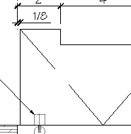
One simple way is to select the first point (A), use Ctrl-RightClick to open the temporary snap menu, pick From, choose point B, and enter the offset. It's a little tricky the first few times you do it, because you have to get the order of the inputs correct. By the way, this works for any grip selection, not just the stretch command. When you finish this task, go over the other options on that menu, you'll find several that should help you in your daily routine. If this doesn't solve your issue, please provide more information. -
Hi, I'd like to stretch the lower frame from point A to be an exact amount from point B. Is there a way to "acquire" the second point within the stretch command but only as reference? Thanks!
-

quick xyz coordinates text placed from selected points
CivilTechSource replied to pavanetc's topic in AutoLISP, Visual LISP & DCL
Just use a point and insert Field in Mtext and format it how you want. When copying both point and text it will keep the new copied items linked. Regen to update the coordinates. -
 mosa1293 joined the community
 -

quick xyz coordinates text placed from selected points
Tsuky replied to pavanetc's topic in AutoLISP, Visual LISP & DCL
You can also use fields with selection of points? (defun make_field (ent / pt obj) (setq pt (trans (cdr (assoc 10 (entget ent))) 1 0)) (mapcar '(lambda (lx) (apply '(lambda (ins_point value_field att_point txt_height dwg_dir name_layer txt_rot / nw_obj) (setq nw_obj (vla-addMtext Space (vlax-3d-point (trans ins_point 1 0)) 0.0 (strcat "{\\f@Arial Unicode MS|b0|i0|c0|p34;\\Q15;" "%<\\AcObjProp.16.2 Object(%<\\_ObjId " (itoa (vla-get-ObjectID (vlax-ename->vla-object ent))) value_field "}" ) ) ) (mapcar '(lambda (pr val) (vlax-put nw_obj pr val) ) (list 'AttachmentPoint 'Height 'DrawingDirection 'InsertionPoint 'Layer 'Rotation) (list att_point txt_height dwg_dir ins_point name_layer txt_rot) ) ) lx ) ) (list (list (mapcar '+ (trans pt 1 0) (list (getvar "TEXTSIZE") (+ (* (getvar "TEXTSIZE") 1.25) (getvar "TEXTSIZE")) 0.0)) ">%).Coordinates \\f \"%lu2%pt1%pr3%ps[X:,]\">%" 4 (getvar "TEXTSIZE") 5 "Id-XY" rtx ) (list (mapcar '+ (trans pt 1 0) (list (getvar "TEXTSIZE") 0.0 0.0)) ">%).Coordinates \\f \"%lu2%pt2%pr3%ps[Y:,]\">%" 4 (getvar "TEXTSIZE") 5 "Id-XY" rtx ) (list (mapcar '- (trans pt 1 0) (list (- (getvar "TEXTSIZE")) (+ (* (getvar "TEXTSIZE") 1.25) (getvar "TEXTSIZE")) 0.0)) ">%).Coordinates \\f \"%lu2%pt4%pr3%ps[Z:,]\">%" 4 (getvar "TEXTSIZE") 5 "Id-Z" rtx ) ) ) ) (defun c:point-xyz_field ( / htx rtx AcDoc Space ncol ss n) (initget 6) (setq htx (getdist (getvar "VIEWCTR") (strcat "\nSpecify the height of the field <" (rtos (getvar "TEXTSIZE")) ">: "))) (if htx (setvar "TEXTSIZE" htx)) (if (not (setq rtx (getorient (getvar "VIEWCTR") "\nSpecify the orientation of the field <0.0>: "))) (setq rtx 0.0)) (vl-load-com) (setq AcDoc (vla-get-ActiveDocument (vlax-get-acad-object)) Space (if (= 1 (getvar "CVPORT")) (vla-get-PaperSpace AcDoc) (vla-get-ModelSpace AcDoc) ) ncol '(96 174) ) (foreach n '("Id-XY" "Id-Z") (cond ((null (tblsearch "LAYER" n)) (vlax-put (vla-add (vla-get-layers AcDoc) n) 'color (car ncol)) ) ) (setq ncol (cdr ncol)) ) (while (null (setq ss (ssget '((0 . "POINT")))))) (repeat (setq n (sslength ss)) (make_field (ssname ss (setq n (1- n)))) ) (prin1) ) -

Small dot appears near MTEXT and cannot be deleted
CHAKRADHAR replied to CHAKRADHAR's topic in AutoCAD 2D Drafting, Object Properties & Interface
Thanks for letting me know. I’ve noted it. -
Small dot appears near MTEXT and cannot be deleted
SLW210 replied to CHAKRADHAR's topic in AutoCAD 2D Drafting, Object Properties & Interface
No, I'm not giving out my email, nor should anybody else. Just simply provide a new draw with a MText with the problem, you can change the wording as well. It may be something a STRIP FORMATING LISP would fix or maybe go into the MText properties and remove the formatting manually. Anything else and I would need the .dwg. -

Small dot appears near MTEXT and cannot be deleted
fuccaro replied to CHAKRADHAR's topic in AutoCAD 2D Drafting, Object Properties & Interface
Just a word of warning: I would not post my e-mail address in a public post... -
Viewport Inset Generator
CivilTechSource replied to CivilTechSource's topic in AutoLISP, Visual LISP & DCL
@BIGAL So in principal I agree with your approach draw rectangles along the selected viewports, send to model space and then select the key plan to bring them back to paperspace. The problem I faced I stumbled across is that you can not define which viewport to CHspace without the user selecting the viewports. So my idea of the optimal workflow/lisp would look something like this: 1. Select Key Plan Viewport 2. Select Insert Viewports 3. Draw Rectangle on all Inset viewports 4. Send Rectangles to ModelSpace of each Inset viewport (So they are at the right scale). 5. Bring all rectangles to PaperSpace through the Key Plan Viewport.