All Activity
- Past hour
-
 emmeci joined the community
 -

The pound sign wobbles textreplacer
pkenewell replied to bustr's topic in AutoLISP, Visual LISP & DCL
Why not just use the built-in FIND command in AutoCAD? You just have to turn off the "Use Wildcards" option.
- Today
-
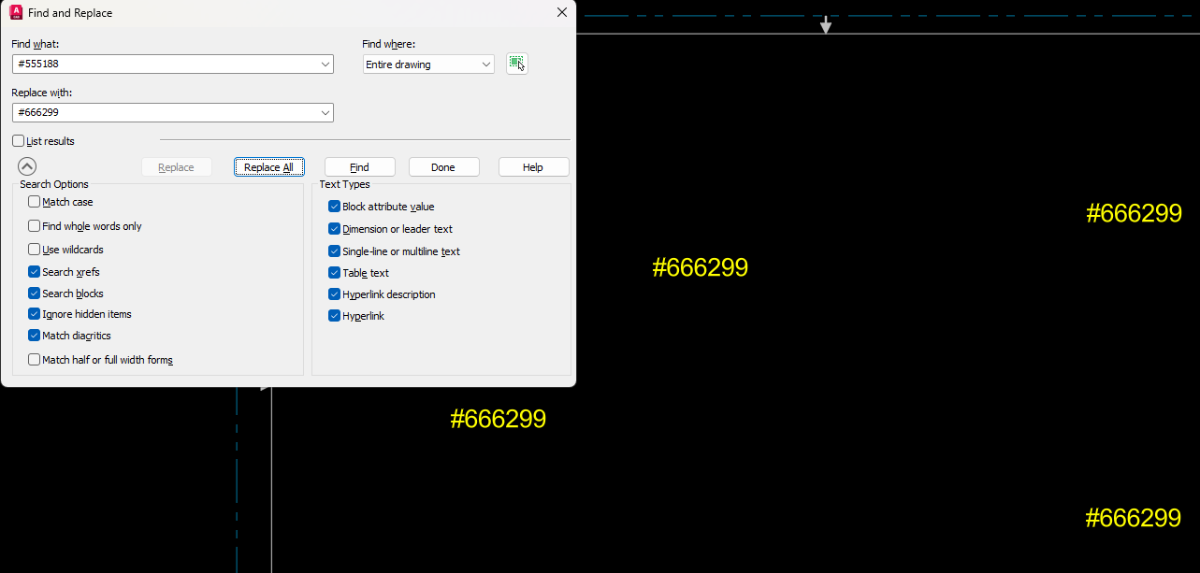
The text replacer lisp refuses to work when there is a # in the text string tobe replaced or the string to replace it. Does anyone know how to fix? revised per #555188 revised per #666299 TXTREPLACE.LSP
-
 gglorja joined the community
 -

autocad 3d multi layout problem with transparency
jim78b posted a topic in AutoCAD 3D Modelling & Rendering
if i publish to pdf multi sheet layout the transparency items appear like in photo, with a lot of lines. why? if i remove silhoutte edges the problem solve, but i want line thickness.
-
 joeywiii joined the community
 -
 manjunath joined the community
 -

zwcad SHX Text Not Editable in PDF
SLW210 replied to CHAKRADHAR's topic in AutoCAD Drawing Management & Output
The OP seems to have exited the conversation, but just for others with the same inquiry. As I have mentioned, this is mostly an issue with your PDF editor, the instructions for using the OCR should be in Foxit Help. If this is something you need to do going forward without any effort, you need to use TTF. -
Node of Arc Length Dimension
SLW210 replied to dickeychan's topic in AutoCAD 2D Drafting, Object Properties & Interface
I moved your thread to the AutoCAD 2D Drafting, Object Properties & Interface Forum. It is indeed a pain. Your only options AFAIK, use LIMITS instead of EXTENTS or EXPLODE the Dimension. -
 Spigi116 joined the community
 -

Help with Penn Foster structural drafting plate 1
ReMark replied to JimJames1978's topic in Student Project Questions
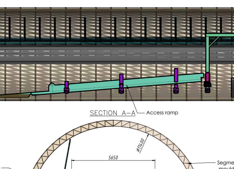
The student should have already drawn the channels, in sectional view, prior to sheet 4. All you are being asked to do is provide an enlarged view since you are creating a detail sheet. Refer to American Standard Steel Channels: Weight, Dimensions, & Properties. Copy the sectional view of one of your channels (previously drawn prior to Sheet 4), paste it in your new sheet, then use the Scale command to enlarge the geometry by the necessary scale factor called for in your instructions. -
 dickeychan joined the community
 -
Node of Arc Length Dimension
dickeychan posted a topic in AutoCAD 2D Drafting, Object Properties & Interface
is there any opinion to "hide" the center node...? sometime I use DimArc at Pspace, the center node shown outside the title block... (or DimArc at Mspace, the center node shown at the outer space...) it affects Zoom~Extents and choosing Extents as plot area... (gotta use Window to point-pick plot area... it's pretty trouble as I use Page Setup to Publish outputs very often...) -
 Emil.larsson1 joined the community
 -
 Flo joined the community
 -
Blank DWG with a large file size...
Flo replied to lamensterms's topic in AutoCAD Drawing Management & Output
Look with Civil3D in Toolspace ; Settings ; Pipe Network ; Delete part lists like Full Part List if they exist. -
 stankits joined the community
 - Yesterday
-

zwcad SHX Text Not Editable in PDF
tombu replied to CHAKRADHAR's topic in AutoCAD Drawing Management & Output
As most of us use Microsoft Office products I switched from using AutoCAD's Swiss Lt BT TrueType font to ArialNarrow.ttf like SLW210 suggested as it's horizontally compressed to take up less space while being even more easily readable. While hindsight doesn't fix your immediate problem finding a font that doesn't cause issues with your PDF software before you need to output one to PDF again would solve your issues in the future. I've struggled with the same issue even with the full paid version of Adobe with drawings by others usually because of SHX text with various width factors. Never do that with a DWG you want to output to PDF unless you don't want anyone to convert that text back again. -
Can you post a sample dwg, tested on dummy dwg's.
-

Help with Penn Foster structural drafting plate 1
TimC replied to JimJames1978's topic in Student Project Questions
Alright, I've been searching and searching on here and I feel like an idiot but maybe it's all the OT I've been working and I'm tired but I'm TOTALLY lost on sheets 4 and 5. I was hoping to be done with this structural project today or tomorrow so I could get to working on the civil since I have a promotion waiting for me at work when it's done and this whole project is driving me nuts. I'm not even gonna use any of this whole degree. I just have to appease "pencil pushers" so here I am. Ok, rant over....lol...more specifically, where do I find the dimensions for this stuff?
-
I've just tried the above code with the necessary changes but cannot get it to work for some reason. Running the code as written produces no change in any attributes. I've changed the file path to be correct, as well as replacing "MATERIAL" with a tag name that is actually used in my blocks. It also seems that this portion: (foreach att atts (setq tname (vlax-get att 'Tagstring)) (if (= tname "MATERIAL") (vlax-put att 'Textstring "TEST") ) changes all tags of a certain type to a new value. I would like to change the value of the tag named "RATING1" for all components with value "CT-1" in tag named "COMPID", and do this across all drawings. All of that to say, I'm new to this and probably just using it incorrectly, but after doing all the learning that I can for now, I'm not sure what I'm doing wrong, or if the code's intention matches my goal.
- Last week
-
Attention fellow Penn Foster structural drafting students....
ReMark replied to TimC's topic in Student Project Questions
I am not aware of any major changes. They may have revised the project instructions re: errors, misspellings, etc. -

Vehicle Tracking - where to find details for vehicles
Steven P replied to Adam - Inspire's topic in Autodesk Software General
I might just do that!! -

Vehicle Tracking - where to find details for vehicles
BIGAL replied to Adam - Inspire's topic in Autodesk Software General
Have a go at adding this vehicle, they are daunting when you meet them on the road. Let alone the 3 x 19m petrol tankers. Recording 2026-03-01 183700.mp4 -
Attention fellow Penn Foster structural drafting students....
TimC replied to TimC's topic in Student Project Questions
yep I've been on here all morning. I know there was some mention of some slight changes to the plans over the years. Do you know if any major changes were made from 2018 to now? I'm seeing some conflicting versions and I wasn't sure if there were changes or if some drawings weren't finished yet -
Attention fellow Penn Foster structural drafting students....
ReMark replied to TimC's topic in Student Project Questions
If you finished the residential house project, then you shouldn't have any problems with the structural project. Plan view, elevation view, sectional view and details is pretty much a standard whether it is a house that is being designed or a commercial building (ex. - warehouse, office building, etc.). -
Attention fellow Penn Foster structural drafting students....
ReMark replied to TimC's topic in Student Project Questions
Images of Plate 1, of the Penn-Foster structural project, are posted throughout various threads contained within this forum. -
 funtwo joined the community
 -
Pline Script File Keeps Failing
BIGAL replied to Rayan O's topic in The CUI, Hatches, Linetypes, Scripts & Macros
You have a few choices in executing this task, you can add a macro in Excel rtaher than write a script asks for a point in your CAD, Acad or Bricscad plus others, then puts the value into your spread sheet X & Y so co-ordinates are made for the pline. Your macro than adds the pline by calling a Sub in Excel. 3 pt pline for you just call the co-ords in a loop. Sub alan3() 'Dim coords(0 To n) As Double Dim coords(0 To 5) As Double coords(0) = -6: coords(1) = 1: coords(2) = 3: coords(3) = 5: coords(4) = 7.55: coords(5) = 6.25: col = 1 Call addpoly(coords, col) End Sub The other way is to read the co-ords from Excel it looks like there a fixed number of rows. Can enter X & Y from cad via a pick point, then read co-ords. That seems simplest for moment as Excel is doing the calculations. I did something similar for some one else and looked at converting to all in lisp but the lookup tables were getting immense so just wrote and read Excel. The only question I guess is which MS12, IB11 and so on.may be able to do a front end for that choice. Will have a go at say MS12 as a start. let me know if on correct path, ; https://www.cadtutor.net/forum/topic/99002-pline-script-file-keeps-failing/ ; read excel draw pline : By AlanH Feb 2026 (defun c:wow ( / myxl mysheet row lst k) (defun getcell (cellname / ) (setq myRange (vlax-get-property (vlax-get-property myxl "ActiveSheet") "Range" cellname)) (princ (vlax-variant-value (vlax-get-property myRange 'Value2))) ) ; Count will be 0 if no excel open but if no workbooks also may return same value. Nil names. ; So a double check count /=0 and wb not "" (princ "\nOpening Excel...") ;; Try to get or create Excel instance (setq myxl (vl-catch-all-apply 'vlax-get-or-create-object '("Excel.Application"))) (if (vl-catch-all-error-p myxl) (progn (prompt "\nError: Could not start Excel.") (exit) ) ) (if (= (vlax-get-property (vlax-get-property myXL 'WorkBooks) 'count) 0) (vlax-invoke-method (vlax-get-property myXL 'WorkBooks) 'Add) ) (vla-put-visible myXL :vlax-true) (vlax-put-property myxl 'ScreenUpdating :vlax-true) (vlax-put-property myXL 'DisplayAlerts :vlax-true) (setq mySheet (vl-catch-all-apply 'vlax-get-property (list (vlax-get-property myxl "Sheets") "Item" "XY Table"))) (vlax-invoke-method mySheet "Activate") (setq row 52) (setq lst '()) (repeat 7 (setq lst (cons (getcell (strcat "B" (rtos row 2 0))) lst)) (setq row (1+ row)) ) (setq lst (cons "C" lst)) (setq lst (reverse lst)) (setq oldsnap (getvar 'osmode)) (setvar 'osmode 0) (setq k -1) (command "pline") (repeat (length lst) (command (nth (setq k (1+ k)) lst)) ) (command "Zoom" "E") (setvar 'osmode oldsnap) (if (not (vlax-object-released-p myXL))(progn(vlax-release-object myXL)(setq myXL nil))) (princ) ) draw object xl bricscad.xlsm draw object xl acad.xlsm -

Pline Script File Keeps Failing
Rayan O replied to Rayan O's topic in The CUI, Hatches, Linetypes, Scripts & Macros
See the two sheets attached. First one is the dimensions, second is the one where the PLINE command is written. PLINE Example.xlsm -
2025 Draw Hatch in lisp or using command line
BIGAL replied to Strydaris's topic in AutoLISP, Visual LISP & DCL
Have a look at this it's a hatch answer, may be similar to what you want. https://forums.autodesk.com/t5/visual-lisp-autolisp-and-general/problem-with-lisp-files/td-p/14027683 Let me know if want more info. -
Pline Script File Keeps Failing
BIGAL replied to Rayan O's topic in The CUI, Hatches, Linetypes, Scripts & Macros
If you have a Excel spreadsheet with the info like the DCL above, you do not need the XY points calculated as they will be calculated by the lisp. Can you post the Excel or at least an image. PS can read Excel from CAD. -
Pline Script File Keeps Failing
Rayan O replied to Rayan O's topic in The CUI, Hatches, Linetypes, Scripts & Macros
I just am not that familiar with LISP commands, never used them. This is my first time where I needed many sections. Plus the geometry was defined on excel based on the contract plans. Chamfer thicknesses vary linearly. -
Pline Script File Keeps Failing
BIGAL replied to Rayan O's topic in The CUI, Hatches, Linetypes, Scripts & Macros
Any reason why you would not use a lisp ? Very simple shape to make. Just ask. The DCL front end took 1 minute to make. Could add more shapes.
-
2025 Draw Hatch in lisp or using command line
Steven P replied to Strydaris's topic in AutoLISP, Visual LISP & DCL
Am not sure if that would work, I use something along the lines of this link: But Lee Macs code - the one I use is VLA- and VLAX- so not sure it would work in LT. There is a simpler example entmake a hatch which might be what you want to do?