All Activity
- Past hour
-

Testing DWG compatibility with different CAD applications
SLW210 replied to indiancad's topic in Catch All
Once again please mention the ActCAD you used for the testing, it also wouldn't hurt to mention what CAD you compared. ActCAD is IntelliCAD based. Looks to be priced very nicely as well. - Today
-

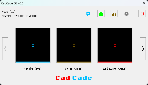
Can CAD be an online battle platform? I decided to try it.
VicoWang replied to VicoWang's topic in AutoLISP, Visual LISP & DCL
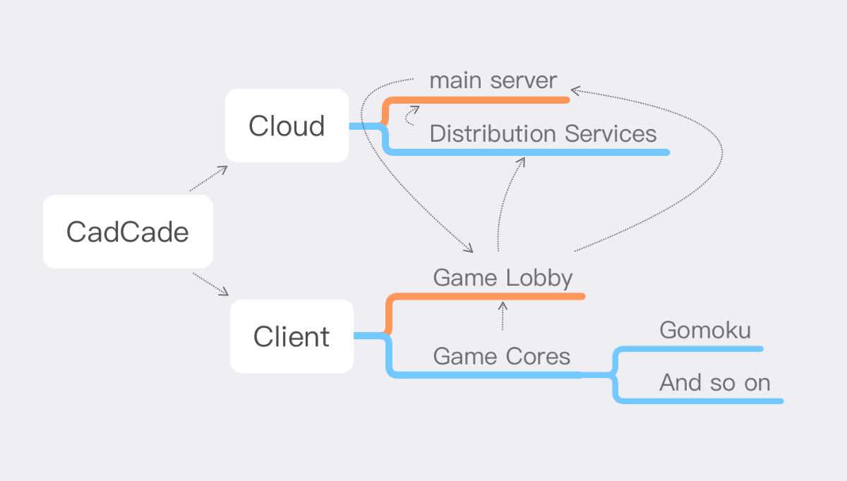
The framework of CadCade has been clarified. A connected game is handled by an independent distributed server, which transmits the match results to the main server for scoring and ranking. A separate CadCade game client is created to unify account settings, network matching, game startup, and provide data interfaces to the core. The Gomoku game is made into an independent game algorithm core (a function library, a plugin type without command preloading in VC), which can be expanded to multiple game cores (pure algorithm libraries, communicating with the hall through interfaces) in the future.
-
What are your best practices for working with large DWG files?
SLW210 replied to indiancad's topic in Catch All
So name the other CAD platforms tested since that would seem relevant and include your thoughts on each if you don't mind. Also, there are three versions of ActCAD, which did you test? If you tested Premium, I would be interested into the import and export of different file types. I did notice the Premium shows the Dassault Systems Spatial logo, so should be using Spatial products for most of that or maybe just ACIS? -

What Is a DWG File? How to Open and View DWG Drawings
The AutoCAD Blog posted a topic in AutoCAD Blogs
What is a DWG file? A DWG file is one of the most common file types you’ll run into when working with CAD drawings. If someone sends you a floor plan, mechanical layout, site plan, or detailed construction drawing, there’s a good chance it may arrive as a .dwg. Quick answer: A DWG file is a CAD drawing file used to store design data for 2D drawings and 3D models. It can include geometry, layers, dimensions, annotations, and other project information used in drafting, design, engineering, architecture, construction, and manufacturing workflows. You may encounter a DWG file even if you’re not a regular CAD user. Maybe a contractor sent over a floor plan. Maybe a manufacturer shared a part drawing. Or maybe you downloaded project files and need to know what software can open them. This blog explains what the DWG file format is, what kinds of data DWG files can store, how they’re used across design and drafting workflows, and how to open DWG files with tools such as AutoCAD software or a DWG file viewer. What Is the DWG File Format? The DWG file format is the native drawing file format for AutoCAD and one of the most widely used formats for creating, editing, and sharing CAD files across design workflows. It helps preserve the drawing information professionals need to review and revise work, from precise geometry and layers to dimensions, annotations, and other project details. DWG is closely tied to computer-aided design (CAD) because it supports editable, accurate drawing data. That matters when a file needs to move from one project stage to another: a concept layout becomes a construction document, a shop drawing moves into review, or a manufacturing detail gets revised before production. What data can a DWG file store? A DWG file can store much more than the lines you see on screen. It can carry the design data that helps a drawing stay useful as it moves through drafting, review, revision, sharing, and documentation. Common types of information stored in a DWG file include: 2D geometry, such as lines, arcs, circles, polylines, and shapes 3D model data, when the drawing includes three-dimensional design information Layers that organize drawing objects by discipline, system, material, or purpose Dimensions that communicate measurements, spacing, tolerances, or other design requirements Annotations, notes, labels, and text used to explain the drawing Blocks and symbols, such as doors, fixtures, fasteners, title blocks, or standard details Layouts and sheets prepared for plotting, printing, or sharing Metadata and other project information that help describe or manage the drawing That range of information is one reason DWG files are common in design and drafting projects. A DWG can support the visible drawing, but it can also preserve the structure behind it, which matters when different people need to open, edit, review, or convert the file later. What software supports DWG files? Several Autodesk tools support DWG files, but the right choice depends on what you need to do next. Opening a file for a quick review is different from editing a production drawing, converting a file, or collaborating with others online. <?xml encoding="utf-8" ?>ToolBest forAutoCADCreating, editing, documenting, and working with DWG files in full CAD workflowsAutoCAD LT2D drafting, editing, and documentation with DWG filesAutoCAD WebOpening, reviewing, and editing DWG files in a web browser and on mobile devicesAutodesk ViewerViewing and sharing DWG files online without installing CAD softwareDWG TrueViewViewing DWG files and converting them to earlier DWG file versions Some non-Autodesk CAD programs may also support DWG files. Compatibility can vary, though, especially when a drawing includes specific objects, file versions, custom data, or features that another program may not fully read. When accuracy matters, use the tool that best matches the work: view, edit, convert, or collaborate. DWG vs. other CAD file formats DWG is one of several CAD file formats used in design workflows. The main difference is intent. Some formats are built for editing. Others are better for exchanging, viewing, publishing, or transferring design data between tools. <?xml encoding="utf-8" ?>File formatPrimary useWhen to use itDWGCreating and editing CAD drawingsUse DWG when you need to work with editable 2D or 3D design data, especially in AutoCAD-based workflows.DXFExchanging drawing data between CAD programsUse DXF when you need to share drawing information with another CAD application that may not use DWG as its main format.DWFSharing and publishing design informationUse DWF when you need to distribute a design for viewing, markup, or review without sending the full editable drawing file.STLTransferring 3D model geometry for fabrication workflowsUse STL when you need a 3D model format commonly associated with 3D printing or other geometry-based transfer needs. For most drafting and design work, DWG is the file you’ll use when the drawing still needs to be edited, coordinated, or developed. Other formats often come into play when the file needs to move outside that working environment. Common uses for DWG files DWG files show up in many drafting and design projects because they can support editable drawing data, structured project information, and file sharing across teams. That makes the format useful when a drawing needs to move from concept to documentation, review, revision, or production. Common uses for DWG files include: Floor plans for residential, commercial, or industrial spaces Construction drawings used by architects, engineers, contractors, and project teams Site plans that show property layouts, utilities, access points, grading, or surrounding conditions Engineering drawings for mechanical, electrical, civil, or structural work Product designs and manufacturing details used to describe parts, assemblies, or fabrication requirements 2D drafting files for plans, elevations, sections, details, schematics, and diagrams 3D drafting or model files when a project includes three-dimensional design information Review and collaboration files shared between designers, consultants, clients, or production teams In short, you’ll often encounter a DWG file anywhere precise design information needs to stay editable, measurable, and ready for the next person in the workflow. Open, view, or convert DWG files with Autodesk tools Once you know what a DWG file is, the next step is choosing the right tool for the task. You may only need to view the drawing. You may need to convert it. Or you may need to edit the file as part of a CAD workflow. <?xml encoding="utf-8" ?>If you need to…Autodesk tool to considerView a DWG file onlineUse Autodesk Viewer to open and review DWG files in a browser.View or convert a DWG fileUse DWG TrueView for DWG viewing and file conversion.Edit a DWG file in a browserUse AutoCAD Web to open, review, and edit DWG files online.Create and edit DWG files in a full CAD environmentUse AutoCAD for DWG drafting, design, and documentation. For a quick look, a viewer may be enough. For ongoing drafting, editing, or documentation, use an AutoCAD tool that supports the level of control your work requires. DWG file FAQs What does DWG stand for? DWG is commonly understood as shorthand for “drawing.” In CAD workflows, a DWG file is a drawing file that stores design information used for drafting, modeling, documentation, and review. The term is closely associated with AutoCAD because DWG is the native file format for AutoCAD drawings. Over time, it has become one of the most familiar file types in professional design and drafting work. Is a DWG file a CAD file? Yes. A DWG file is a type of CAD file used in design and drafting workflows. It can store precise drawing data, including geometry, dimensions, annotations, layers, layouts, and other project information. That makes DWG files useful across many drafting and design projects, from architectural plans and engineering drawings to manufacturing details and construction documentation. Can you open a DWG file without AutoCAD? Yes. You can open and view DWG files without installing AutoCAD software, depending on what you need to do with the file. If you only need to view a drawing, Autodesk Viewer lets you view DWG files online in a browser. If you need to view or convert DWG files, DWG TrueView supports DWG viewing and conversion. If you need to edit drawings, consider AutoCAD, AutoCAD LT for 2D drafting and documentation, or AutoCAD Web for browser-based DWG viewing and markups. Can DWG files store 3D data? Yes. DWG files can store 3D data when the drawing includes three-dimensional design information. They can also store 2D geometry, layers, dimensions, annotations, layouts, and other project details. This flexibility is one reason the format is used across different project types. A DWG file might contain a simple 2D plan, a detailed 3D model, or a drawing set with both model and documentation information. What is the difference between DWG and DXF? DWG is commonly used as a working file format for creating and editing CAD drawings, especially in AutoCAD-based workflows. DXF is often used to exchange drawing data between different CAD programs. A simple way to think about it: DWG is often the file you continue editing, while DXF can help transfer drawing information between software tools. The best choice depends on whether you need to keep working in the drawing or share it with another system. Can DWG files be converted to other file formats? Yes. DWG files can often be converted to other formats for viewing, sharing, publishing, or compatibility with another CAD application. The right conversion path depends on the destination format and what information you need to preserve. For example, you may need to keep editable CAD data, create a viewable file for review, or prepare a file for someone using different software. DWG TrueView can help view and convert DWG files, while AutoCAD tools can support broader editing and export workflows. The post What Is a DWG File? How to Open and View DWG Drawings appeared first on AutoCAD Blog. View the full article -

Testing DWG compatibility with different CAD applications
Danielm103 replied to indiancad's topic in Catch All
If I’m not mistaken, ACTCAD uses ITC/ODA libraries. DWG compatibility should be good. -
.thumb.jpg.615654602253be56b2fbd5d064834780.jpg)
What are your best practices for working with large DWG files?
indiancad replied to indiancad's topic in Catch All
Thanks. I included ACTCAD because I was testing the same files across multiple CAD platforms under similar conditions. During the process, I also received a technical demo on large-file performance, troubleshooting, and useful cleanup commands, which helped me understand some of the performance issues better. Overall, the testing was mainly about comparing practical workflows rather than choosing one particular CAD platform. -
What are your best practices for working with large DWG files?
SLW210 replied to indiancad's topic in Catch All
Do you have actual numbers to support your claims for ACTCAD, or just a general feeling of being better? What "other" CAD applications did you compare? Are you only here to advertise ACTCAD? You have another thread making ACTCAD comparisons and you appear to be associated with a seller of ACTCAD. Back on topic, Xrefs, Blocks and general drawing cleanups, Audits, -Purge, etc. help a lot, but to be honest, the actual file size can be irrelevant, even small file sizes containing certain objects can cause issues. My biggest slow down at work is the choked off network and ITs issues with security software, etc. and yes, some of that is Autodesk's License verification, etc. and my company isn't a CAD work company, I just support manufacturing, facilities, etc. so IT priority is not Autodesk connectivity and performance. I have worked on files that were a struggle at work on my old slow home computer and they ran just fine. But, no doubt, if you work regularly with large files a powerful workstation would definitely be a must have. -
 dozza6570 joined the community
 -

Standard texts are hiding somehow can anyone please help??
animal1103 replied to Vijay's topic in AutoCAD 2D Drafting, Object Properties & Interface
可能使用了背景遮罩 -
 tomai joined the community
 -
What are your best practices for working with large DWG files?
indiancad replied to indiancad's topic in Catch All
yes !that absolutely right; then what about who wants to open large dwg files. when they can't afford the features you mentioned. -

What are your best practices for working with large DWG files?
BIGAL replied to indiancad's topic in Catch All
Best processor, graphics card and lots of ram. A very simple answer. - Yesterday
-
What are your best practices for working with large DWG files?
indiancad posted a topic in Catch All
Large DWG files can become difficult to work with when they contain thousands of objects, blocks, hatches, XREFs, and detailed drawings. I’ve been testing the same larger DWG files in different CAD applications to compare practical performance during opening, zooming, editing, saving, and switching between layouts. ACTCAD was one of the applications I tested, and I was pleasantly surprised with how smoothly some of the larger files handled. I’m curious about the experience of other CAD users here. What techniques do you normally use to keep large DWG files fast and responsive? -
GitHub vs APPLOAD: Why is our global impact invisible?
VicoWang replied to VicoWang's topic in AutoLISP, Visual LISP & DCL
I completely understand why seeing a "Sign In" button triggers the password fatigue alarm! But if you actually click that button, it redirects you to our Web Portal (app.vedacad.com — I’ve attached a screenshot for you). You won't find a "Create Password" field anywhere in our system. It operates entirely via one-click OAuth, secure Magic Links sent to your email, or Enterprise SSO (OIDC) for corporate users. no new passwords. As for your summary: "a fancy DCL popup that links to an online file store"—from a draftsperson's perspective, I take that as a huge compliment! It should feel that incredibly simple. The ultimate goal is zero friction. But under the hood, that "fancy DCL" is just the visual shell for a robust LISP microkernel. Here is what it's actually doing in the background: Isolated Sandbox & Proxying: It doesn't just download files; it vaults them in a secure local sandbox (%APPDATA%) and dynamically generates demand-load proxy hooks in memory, keeping your CAD startup footprint at 0%. Environment Injection: It natively reads and injects configuration files (.CTB, .DWT, .SHX, .CUIX) directly into AutoCAD's Preferences and Support Paths, silently aligning the drafting standards without the user lifting a finger. Lock-Bypass Hot-Swapping: It handles Windows file locks natively. If a developer pushes an update, the kernel re-routes the running binary (via .bak renaming) to silently hot-swap the .vlx or .dll while the user is actively drafting. Zero-Trust MDM: For enterprise deployments, it constantly listens for kill-switch directives to physically shred revoked assets (like expired sub-contractor standards) from the local hard drive. So yes, it looks like a simple popup, but it hides an entire IT deployment and environment governance engine behind it.
-

GitHub vs APPLOAD: Why is our global impact invisible?
Steven P replied to VicoWang's topic in AutoLISP, Visual LISP & DCL
? Suggests another profile, sign in, password to manage. So for my simple understanding, it is a fancy DCL popup that links to the company or online file store? (and do remember, I am not a cloud architect, I draw stuff for a living and create LISPs to make that easier)
-
I've been testing the same DWG files across different CAD applications and comparing how they handle layers, blocks, dimensions and XREFs. One interesting thing I've noticed is that DWG compatibility isn't just about opening the file—it also matters how accurately the drawing behaves when edited and saved. Has anyone here compared different DWG-compatible CAD applications on the same project files? "ACTCAD was one of the applications I tested." , and so far it has handled my DWG files quite well, including layers, blocks and XREFs. I’d be interested to hear if others have had similar or different experiences with ACTCAD or other DWG-compatible CAD software.
-
GitHub vs APPLOAD: Why is our global impact invisible?
VicoWang replied to VicoWang's topic in AutoLISP, Visual LISP & DCL
Hi Steven, Those are incredibly valid points, and they highlight exactly why we built VedaCAD the way we did. You perfectly described the classic "Enterprise IT Roadblock." To clear up the confusion, VedaCAD is absolutely not a cloud drive (like Dropbox) where you copy and paste files. It is an infrastructure that pipes routines directly into the CAD environment. Let me address your concerns directly, because reducing deployment friction is actually our core design philosophy: 1. No new passwords to remember. We hate account fatigue as much as you do. VedaCAD operates entirely password-less. You either use one-click OAuth (Google, Microsoft, Autodesk) or a secure Magic Link sent to your email. Enterprise(CORP) users log in directly using SSO(OIDC), and there is no password field stored in our system. 2. Zero-Install Footprint (Reducing Deployment Friction). This is the most important part. There is no .exe or .msi installer, and it does not require Windows Administrator rights. The entire VedaCAD client is just a single 1.6MB pure LISP (.vlx) file. It operates completely within the standard bounds of AutoCAD. We strictly manage a secure local sandbox inside the user's directory (%APPDATA%)—there is no Windows Registry injection, no background Windows services, and zero OS-level modifications. If your IT department currently allows you to type APPLOAD for normal LISP routines, VedaCAD complies perfectly with those existing security rules. It is designed to save IT from deployment headaches, not to subvert them. 3. Multi-Platform Roadmap. You asked about BricsCAD. Currently, VedaCAD is strictly built for AutoCAD. We intentionally engineered the entire client inside the native AutoCAD 2006 Visual LISP IDE to guarantee absolute backward compatibility. However, because we built it on pure foundational LISP rather than version-specific .NET frameworks, the workload to port it to other platforms is minimal. We are currently laser-focused on perfecting the commercial loop within the AutoCAD ecosystem, but supporting all 4 major platforms (AutoCAD, BricsCAD, ZWCAD, GstarCAD) is definitively on our roadmap. Basically, we built this specifically so engineering teams can seamlessly sync their setups without creating an IT deployment nightmare. Does that help clarify the workflow? --- Since you specifically brought up how IT folks assess suitability, security, and licensing, I should add a quick high-level overview of how VedaCAD actually handles corporate deployments under the hood. Beyond the personal tier, our Enterprise architecture is fundamentally divided into two major workflows: Internal Fleet Management and External Supply-Chain Control. 1. Internal Fleet Management (The Foundry & Squads) Instead of emailing ZIP files to employees, CAD Managers upload their standard plugins and configurations into a web-based "Enterprise Foundry." (All uploads of the company's plugins and environment configuration files must be uploaded from the company (CAD Manager)administrator's client.) From there, admins create internal Squads (e.g., Architecture, Structural) and assign specific toolsets to each group. When an employee logs in, the VedaCAD client silently deploys only their authorized tools into their local sandbox. Zero Fragmentation: IT can monitor the "Out of Sync" status of any terminal globally from the dashboard. Visual SOPs: Admins can attach Markdown manuals and Demo GIFs to assets. Employees simply click the "SOPs" button inside their CAD client, which uses a secure hardware token to instantly log them into their Web Portal to view the exact workflow guidelines for their assigned tools. 2. External Sub-Contractor Control (Project Arks) This is the killer feature for General Contractors (GCs). Enforcing drafting standards across external vendors is a nightmare. Instead of sending CAD standards via email, GCs create a "Project Ark" and issue time-limited, "Visas" to external sub-contractors. Format Firewall: Arks strictly permit only environment configuration files (.CTB, .DWT, .SHX, etc.). Executable plugins (.DLL, .LSP) are physically blocked to prevent cross-company malware infections. Zero-Trust Shredding: When a sub-contractor mounts the Visa, their CAD environment temporarily mirrors the GC's standards. If the Visa expires or is revoked by the GC, the VedaCAD kernel physically shreds those proprietary standards from the sub-contractor's local hard drive. 3. IT Compliance & Data Sovereignty (Add-ons: BYOS & EDR) To pass the strict security audits of large institutions, our Enterprise tier supports BYOS (Bring Your Own Storage). You can route 100% of your physical CAD assets directly to your company's private AWS S3 bucket—we never touch your binaries. We also offer native EDR Gateway integration, allowing your corporate SecOps sandbox to automatically intercept and quarantine any unverified payloads before they reach the draftsperson's machine. In short, it’s designed to give IT absolute control over data sovereignty and access, while giving CAD Managers a frictionless way to enforce standards. -
GitHub vs APPLOAD: Why is our global impact invisible?
Steven P replied to VicoWang's topic in AutoLISP, Visual LISP & DCL
I am getting confused now as to the function of your cloud repository - OK I get a file store, we log in if we want (I don't actually care to create myself another internet profile with another unique password to manage, and another online service), upload files, others can copy and paste as required. In a crowded market, it might be the best solution out there, it might not. But then there is some integration into CAD (Just AutoCAD or others such as BricsCAD?). This part I am not sure about. Does this need software installing to manage this, and if so I believe our IT folks will be giving it a thumbs down till they have assessed suitability, its security, licensing agreements, ongoing costs ad so on. -
 bing00118 joined the community
 -
GitHub vs APPLOAD: Why is our global impact invisible?
VicoWang replied to VicoWang's topic in AutoLISP, Visual LISP & DCL
Hi everyone, Just a quick follow-up regarding the Pioneer Index and creator profiles. As the VedaCAD ecosystem is starting to grow, I want to strongly recommend that the veteran developers here—and anyone who has shared tools in the past—take two minutes to claim your @username on the platform. Because VedaCAD operates purely as a neutral conduit, account registration is strictly first-come, first-served. We cannot pre-emptively determine who the "real" owner of a community alias is, nor do we have the authority to evict a user or forcefully reassign a handle once it has been claimed by someone else. Since the platform is still in its early stages, right now is the absolute best window to secure your username sovereignty and prevent impersonation. I want to be absolutely clear: You do not need to upload any scripts or actively use the platform. You can simply register your standard forum alias to lock it down. If you prefer to stay completely off the radar, just log in to the Web Portal, go to Settings > Profile, and toggle off "Public Profile". Your @username will be permanently secured to your email, but you will remain 100% invisible on the Pioneer leaderboard and public directories. I just want to make sure the true creators in this community own their rightful identities before someone else grabs them. Cheers, Vico
-

fire protection LISP routine for the distribution of sprinklers and fire detectors in fire protection installations
Javier Longa replied to Javier Longa's topic in AutoLISP, Visual LISP & DCL
Thanks for the advice and the routine. The routine might be useful for spacing elements, but my code generates a distribution based on coverage, taking into account various parameters. Regarding Copilot falling short, I agree, although I don't think I'll continue working on this routine with this AI, at least not yet. And I should mention that I've created other routines, also with Copilot, which is the only AI I have available. I'm also the author of many dynamic and parametric blocks related to fire protection systems. As for learning to program, as I said before, I'm 60 years old and I don't have much time left before retirement. I don't see it as being productive. Maybe as a hobby. And yes, I've searched for the topic "AutoCAD Lisp Sprinklers" many times and I've never found anything that seems useful and is offered for free. -
GitHub vs APPLOAD: Why is our global impact invisible?
VicoWang replied to VicoWang's topic in AutoLISP, Visual LISP & DCL
Hi Daniel, Great to see you bringing pip concepts into this. PyRx is an absolute beast of a project, and you are 100% correct—version tracking and dependency resolution are the holy grails of package management. Since AutoLISP lacks native import statements or .toml manifests, we had to engineer a slightly different approach for VedaCAD to achieve that exact same pip reliability. Here is how we handle it under the hood: 1. Version Tracking & Hot-Swapping (The State Machine) Instead of a manual CLI command like PYPIP Update, VedaCAD uses a background state machine. During the client heartbeat, it sends a lightweight dictionary of its local plugins and their current versions to the cloud. The server diffs this against the master database. If a developer has patched a script, the server pushes an assetUpdates beacon back to the client. Depending on the workspace policy, the client either prompts the user visually, or (for Enforced Enterprise modes) it executes a dual-buffer hot-swap in the background—renaming the old locked .vlxto .bak and injecting the new binary seamlessly. 2. Dependency Resolution (The Bundle System) If your LISP routine strictly depends on "LM:ODBX 1.2", you don't want users hunting for it. In VedaCAD, the developer creates a "Bundle" (a VCID starting with B-). You package your main script AND the LM:ODBX dependency together. By leaving the command alias blank for the ODBX file, VedaCAD flags it as a "System Library" , which forces it to pre-load silently at startup. Your main script remains demand-loaded. The end-user simply pulls ONE B- VCID, and the entire dependency tree is resolved locally. While a CLI interface is undeniably cool for developers, we ultimately went with a unified GUI dashboard (Command: VC). We found that CAD Managers deploying tools to 50+ draftsmen needed a visual matrix rather than teaching their team command-line syntax. It's awesome seeing different modern architectures (Python/PIP vs Cloud/LISP) tackling the same legacy CAD headaches! -
GitHub vs APPLOAD: Why is our global impact invisible?
VicoWang replied to VicoWang's topic in AutoLISP, Visual LISP & DCL
I know there are tools out there that try to execute LISP directly from the cloud, but as you implied, that requires a flawless real-time connection. VedaCAD takes the exact opposite approach. Our architecture is fundamentally built around a "Local Sandbox Cache".When you pull a VCID, the physical file is downloaded as-is and vaulted directly onto the engineer's local drive (e.g., %APPDATA%\VedaCAD\...). Here is how the engine handles network drops: When CAD starts, our microkernel checks the configured heartbeat cycle. If it's within the valid cycle, it skips the network request completely. If the cycle has expired, it sends a lightweight ping to the server to check for version updates or MDM policy changes. If an engineer opens their laptop on a construction site with zero Wi-Fi, that heartbeat ping simply times out. The VedaCAD kernel instantly detects the disconnection and silently transitions into Offline Mode. The engineer keeps drafting seamlessly using their locally cached plugins and menus. No lag, no missing commands, and absolutely zero need to manage a separate "Out of office" profile. Once they reconnect, the background heartbeat simply resumes on the next cycle. In short: The VCID is just a delivery protocol. The actual execution is always local! To accommodate extended field work while protecting enterprise IP, we built in specific Offline Grace Periods: BASE Mode: Air-gapped by default. Works indefinitely without any internet. FREE Tier: 3 days of offline grace. PRO Tier: 15 days of offline grace. TEAM / CORP Tiers: Configured by the CAD Manager (Max 30 days). -
GitHub vs APPLOAD: Why is our global impact invisible?
Danielm103 replied to VicoWang's topic in AutoLISP, Visual LISP & DCL
Not for lisp, but one thing cool about PIP, is it tracks versioning. When you upload a package to PyPi, your package should include a README.MD and a PROJECT.TOML. the toml might look like. requires-python = ">=3.14.0,<3.15.0" dependencies = [ "wxPython>=4.3.1,<4.4", "pywin32; sys_platform == 'win32'", "debugpy>=1.8.0", "pydantic_settings", ] PIP keeps track of every detail for every project and notifies of potential conflicts. Also, it will install dependencies, I.e. Python for AutoCAD requires wxPython, the system will download the modules for you, and also any dependencies wxPython requires. For lisp, something like this would be valuable. dependencies = [ “LM:ODBX 1.2” ... ] Then, have a command in AutoCAD to help manage I.e. Command: PYPIP [List/Install/Remove/Update] <list>: Package Version Editable project location ----------------- ---------------- ------------------------- annotated-types 0.8.0 appdirs 1.4.4 ast_serialize 0.6.0 asttokens 3.0.2 build 1.5.0 cad-pyrx 3.1.6.5712 M:\Dev\Projects\PyRxGit cfgv 3.5.0 click 8.4.2 colorama 0.4.6 debugpy 1.8.21 all of the packages could be streamed into a .bundle for auto loading -
fire protection LISP routine for the distribution of sprinklers and fire detectors in fire protection installations
BIGAL replied to Javier Longa's topic in AutoLISP, Visual LISP & DCL
In the multi getvals.lsp you can preset a value for say the spacing, or even have 2 values for row & column Min max preset. Just add more to the dcl example. Look at the last "1" change it to say '2.4", it must be a string not a number. That way you can come up with a spacing that meets min max criteria. (if (not AH:getvalsm)(load "Multi Getvals.lsp")) (setq ans (AH:getvalsm (list "Enter values " "Row spacing " 5 4 "2.4" "Col spacing " 5 4 "2.4" ))) Multi GETVALS.lsp In the code it uses the lower left as control, but you can find closest vertice to where you picked the pline outline. Then you can set the control of where the spacing starts from. I use a over draft to cover the entire area with sprinklers then erase those out side of the boundary. Even worked for plines with curves.. I think you will struggle with Copilot as you get more complex with extra features, now is a good time to learn programming. Reading code and getting an understanding of what it is doing and you will soon write your own. Plenty out there to help. Lastly did you google Fire sprinklers autocad lisp" ? The topic has been answered before answers may be at "Forums/Autodesk" aka Autocad. - Last week
-
GitHub vs APPLOAD: Why is our global impact invisible?
BIGAL replied to VicoWang's topic in AutoLISP, Visual LISP & DCL
Just a question we had laptops that were used outside no internet access, we had two CAD Icons so they would start the correct profile for "in office" and "out of office", how would your system cope with that ? Would the second profile go looking for the VCID ? -
fire protection LISP routine for the distribution of sprinklers and fire detectors in fire protection installations
Javier Longa replied to Javier Longa's topic in AutoLISP, Visual LISP & DCL
I appreciate those suggestions, of course, but due to my age and the demands of my job, I find it very difficult to learn any kind of programming. I'll continue using Copilot. Regarding what you mentioned @SLW210 about the regulatory values, I don't see any reason to change them. When I created the routine, it was to help my colleagues who are familiar with the values they need to apply, not in a fixed way, but by verifying their validity against the applicable standard. I didn't create the routine for someone unfamiliar with the different fire safety regulations. I've uploaded this application, and I'm repeating myself a lot, sorry, because I don't think I could find anything similar already created by others that was free, and even the existing ones, including those in calculation software, aren't reliable. I also wanted to ask a programming expert to take up the challenge and collaborate on improving it. Following up on this last comment, I'm going to upload a new version that corrects the design when there's a rotation in the UCS, modifies the polyline selection code using Lee Mac's code (thanks to @BIGAL and @Lee Mac), and also includes other considerations. Please excuse me if it's still in Spanish, but as I said, it's primarily for my team's use. PCI_PRO (PFP)_V3_8.lsp -
fire protection LISP routine for the distribution of sprinklers and fire detectors in fire protection installations
SLW210 replied to Javier Longa's topic in AutoLISP, Visual LISP & DCL
Just trying to help you improve your LISP programming, so don't take this as not appreciating what you have done. These suggestions just make it better for everyone and should be doable upgrades, IMO. I would have to know those values in advance. I am sure some people do this everyday and may memorize them, but that is a bad habit to get into. 1. The specifications can change. 2. Some may need to use different standards each project. 3. Some people might mis-remember the values, etc. leading to errors. Programs that deal with a Standard should always employ the standard if possible, even if you make it just for the one you use. For example: Al's Steel Mill and Wisey's, they each employ a different standard for steel shapes and do so with easily updateable files. Here is a thread here on Al's with an updated standards file. Updated AISC Shapes for STL.LSP - AutoLISP, Visual LISP & DCL - AutoCAD Forums There is on CADTutor and maybe some other fora, etc. some programs dealing with piping, they each work towards the respective standards in those industries. ANSI B16.5 Flanges Lisp - AutoLISP, Visual LISP & DCL - AutoCAD Forums There are a few more, but speaking of those flanges, etc. I or someone needs to see if any of those standards have changed since it's been a while. Also, another question, since I rarely have to do sprinklers, etc. that often, does this work with AutoCAD MEP's sprinklers? I'll have to check, but I do not believe they are actual blocks, so that could be another upgrade suggestion.