All Activity
- Past hour
-
The black ceiling is likely caused by the renderer not calculating enough indirect illumination. Increasing material reflectivity alone won't solve this. You need to enable global illumination (GI) or indirect lighting so light can bounce off the floor and surrounding surfaces. Also, check whether your renderer supports bounced light and adjust the indirect illumination settings. Self-illumination can help simulate light sources, but excessive use may produce an artificial appearance.
-

Converting scanned engineering drawings into accurate editable CAD geometry
indiancad posted a topic in AutoCAD Drawing Management & Output
Legacy project drawings are often available only as scanned PDFs or raster images. Converting them into editable DWG geometry can be difficult because paper distortion, scanning errors, and inconsistent image scaling may affect dimensional accuracy. Scaling the image using a single known dimension may not correct distortion across the entire drawing. When converting old scanned drawings, how do you verify geometric accuracy across the full sheet? Do you use multiple control dimensions, image rectification, or manual reconstruction of critical geometry? -
How do you handle slotted holes in precision mechanical drawings?
indiancad posted a topic in AutoCAD 2D Drafting, Object Properties & Interface
Slotted holes are commonly used in mechanical assemblies to allow adjustment during installation. However, specifying their dimensions and positional tolerances can become challenging when the slot must provide sufficient adjustment without compromising the final alignment. A simple length and width dimension may not communicate all the functional requirements, particularly when the slot position is critical to the assembly. When detailing slotted holes, how do you specify their geometry and positional tolerances? Do you use GD&T with a defined datum reference frame, or follow another dimensioning approach? - Today
-

How can I add an Emergency Light Type to existing lights?
AONE_LED replied to brandwmarsh's topic in Revit MEP
Put the half-shaded emergency symbol in a nested Generic Annotation family, not as model lines. In that annotation, draw the normal fixture symbol and a solid half-fill. Select only the half-fill and link its Visibility to a Yes/No parameter, for example EmergencyGraphic. Load the annotation into the lighting fixture family, place it as the plan symbol, and hide the 3D geometry in plan views. Associate the nested EmergencyGraphic parameter with a type parameter of the same name in the host family. Create two types: Normal (unchecked) and Emergency (checked). Switching the type in the project then shows or hides the half-shade, like a single-pole versus 3-way switch. If the graphic does not appear, confirm the annotation is visible in plan/RCP and that you used a type parameter, not an instance one. -
Draft uses a simplified lighting model, so the ceiling can look lit with no bounced light. Low and higher presets use ray-traced direct light only, unless you turn on indirect illumination. A cowling around a downward fluorescent correctly blocks direct light from reaching the ceiling, which is why everything above the fixtures goes black. Turn on Global Illumination and Final Gather in the Render settings. Start with Photons/sample around 500 to 1000 and Final Gather rays around 500, then increase if the ceiling looks blotchy. Give the floor and walls realistic diffuse reflectance (about 0.2 to 0.3 for a floor, 0.5 to 0.7 for walls) so photons can bounce. Also check that the light source is not fully enclosed by the cowling solid; leave a downward opening, or no light escapes. With photometric units on, intensity in candela or lumens needs to be high enough for a 16 ft room.
-
Dialux lighting exported to AutoCAd 2010
AONE_LED replied to ochiara's topic in AutoCAD 2D Drafting, Object Properties & Interface
Each DIALux export usually creates a unique anonymous block (*U...) per luminaire, so BLOCKREPLACE and the Express Tools replace-block command cannot swap them in one step. A reliable workaround is to harvest the insertion data, then place your own named blocks. Use DATAEXTRACTION on all INSERT objects whose names start with *U. Export insertion point X/Y/Z, rotation, and X/Y scale to a CSV. In a clean copy of the drawing, erase the anonymous inserts (FILTER or QSELECT by name *U*), then run a short script or LISP that reads the CSV and inserts your fixture block at each point with the same rotation and scale. If several luminaire types were exported, group them first by layer or by any DIALux type attribute that survived the export. Keep a backup before erasing the *U blocks. - Yesterday
-
 Pramod Kumar joined the community
-
 Alessandro joined the community
-
Associative Textbox (Lee Mac)
Alessandro replied to sachindkini's topic in AutoLISP, Visual LISP & DCL
Dear sir, on my autocad LT 2027, if i generate a TBOX and then i copy and paste the text (both using the command copy and using ctrl+c - ctrl+v), i don't have a copy of the tbox too. Is there a solution for this? -
 cristianrivera25 joined the community
-
Lighting Fixture Schedule - Best Practice
AONE_LED replied to lkenshalo's topic in AutoCAD 2D Drafting, Object Properties & Interface
For lighting schedules in vanilla AutoCAD, a fixture block with attributes plus DATAEXTRACTION is usually the most reliable method. Use a unique type mark (A, B, C) as an attribute at the insertion point, and add attributes for description, lumens, wattage, CCT, voltage, mounting (recessed, surface or pendant) and ceiling cut-out. Keep one block definition per fixture type so the counts stay accurate. DATAEXTRACTION can then build a table of Type, Description, Quantity, Watts and Lumens, and you can refresh it when the layout changes. Excel is still useful for photometric and driver data that does not live in the drawing; DATALINK the finished table back into the sheet so the two stay in step. Avoid mixing a hand-counted grid with extracted quantities, or the schedule will drift. -
Shaped light source - i.e., fluorescent light bulb
AONE_LED replied to SaigoLives's topic in AutoCAD 3D Modelling & Rendering
In AutoCAD 2000 you cannot declare a solid as a light source, and photometric weblights did not exist yet. Model each fluorescent as a simple 26 mm (T8) or 16 mm (T5) cylinder, then place a row of low-intensity point lights along the tube centreline at about 200–300 mm centres so the light is even. Give the tube a pale, slightly self-illuminated material so the lamp reads as glowing in the render; keep the housing as ordinary geometry so it can cast a soft shadow. For a ceiling grid, copy this fixture as a block to each troffer location and aim the lights downward. If you later move to AutoCAD 2007 or newer, set LIGHTINGUNITS to 2 (SI) and use one WEBLIGHT per fixture with a manufacturer IES file instead. -
displaying cove lighting in a relfected ceiling plan?
AONE_LED replied to bbestone's topic in AutoCAD Beginners' Area
Cove lighting on an RCP is usually shown as a continuous dashed or hidden line along the inside face of the cove, not as a row of downlight circles. Put it on its own layer, for example A-CLNG-LITE-COVE, so you can plot it lighter than the ceiling grid. If the cove has a linear LED or fluorescent strip, a single dashed line at the lamp position is enough; a narrow hatch or a double line can indicate a wider light shelf. Tag the run with the fixture type (for example "C1 – LED tape in cove") and note the soffit depth in the legend. Recessed downlights and the ceiling grid stay as solid symbols. Grey-tone RCPs are common: existing work in grey, new lighting and notes in black, all drawn at 1:1 in model space. - Last week
-

Managing tolerance stack-up in assemblies with multiple mating components
SLW210 replied to indiancad's topic in AutoCAD 3D Modelling & Rendering
Do you know GD&T? -
Dynamic block changes are not updating attribute values consistently
indiancad posted a topic in AutoCAD Drawing Management & Output
In projects that use dynamic blocks for equipment layouts, electrical symbols, or standard components, changing visibility states and block parameters can sometimes leave attribute information inconsistent across different block instances. This becomes particularly troublesome when drawings contain hundreds of instances with part numbers, descriptions, or equipment tags that must remain accurate. Commands such as ATTSYNC can synchronise attribute definitions, but they may also affect manually modified attribute values. How do you manage attribute consistency in drawings containing large numbers of dynamic block instances? Do you rely on ATTSYNC, custom AutoLISP routines, or a different block-management workflow? -
Need to export each solid as separate dwg, dxf or 3ds file format
indiancad replied to ADSK2007's topic in AutoLISP, Visual LISP & DCL
This can be automated using AutoLISP with the WBLOCK command. A routine can iterate through all 3DSOLID entities, export each one as a separate DWG, and generate sequential filenames such as Solid-001.dwg. One important detail is to distinguish between preserving the original world coordinates and moving each solid to 0,0,0. Which output do you need: original coordinates or each solid individually positioned at the origin? -
 bander4ik joined the community
-
Managing tolerance stack-up in assemblies with multiple mating components
indiancad replied to indiancad's topic in AutoCAD 3D Modelling & Rendering
Thanks for sharing your approach One concern is that even when individual parts meet their specified tolerances, tolerance accumulation can still create unexpected assembly issues. Do you also perform a tolerance stack-up analysis for critical assemblies, or do you rely mainly on fit classes and standard tolerances? -
Managing tolerance stack-up in assemblies with multiple mating components
indiancad replied to indiancad's topic in AutoCAD 3D Modelling & Rendering
. -
Need to export each solid as separate dwg, dxf or 3ds file format
AONE_LED replied to ADSK2007's topic in AutoLISP, Visual LISP & DCL
When you WBLOCK each solid, leave it at its real world coordinates and use a common base point of 0,0,0 for every file. If you move each solid to the origin before export, DIALux has no relative position left to rebuild the room. Keep the same units in AutoCAD and DIALux (metres is safest); a units mismatch is the usual reason imports appear in the wrong place even when the base point is consistent. Because you already have each solid on its own layer, naming the WBLOCK after the layer is fine. Prefer DWG over 3DS if evo will accept it, and lower FACETRES if the mesh is too heavy. After import, check one known corner against the original coordinates before you assign materials. -
Objects from straight polyline to spline
AONE_LED replied to Joe.'s topic in AutoLISP, Visual LISP & DCL
The existing WOW LISP copies each luminaire to the same distance along the new path, which is the right idea for uneven spacing. One important lighting detail: the routine inserts the block at rotation 0, so fittings will not turn with the curve. When you insert, set the rotation from the path tangent (the direction of the first derivative at that distance) so linear or wall-wash luminaires stay aligned to the run. Also confirm both polylines are measured from the same end; if they run in opposite directions the fixtures will be mirrored along the path. If the curved path is slightly shorter than the straight one, the last fitting may land on the end point — that is usually acceptable for a millimetre-level difference, but check the last spacing on a long street or cove run. -
Problem with IES Lighting particularly its source glow
AONE_LED replied to ThrashMetal's topic in Cameras, Lighting & Rendering
An IES web light only stores the far-field intensity distribution; it does not make the fixture geometry look like it is emitting. Keep the IES light for the room illumination, and give the lamp or diffuser a self-illuminated material (luminance in candelas per square metre) so the source itself glows in the render. Avoid adding a second spherical photometric light on top of the IES file, or you will roughly double the flux in the scene. If the downlight pattern only appears low on the wall, the IES is probably a narrow-beam or recessed cut-off distribution. Check that the web's nadir points straight down, place the light at the real ceiling height, and try a wider-beam IES if you want the scallop higher up the wall. -

Fitting without collision
Discus84 replied to Discus84's topic in AutoCAD 2D Drafting, Object Properties & Interface
Big thanks, this solves the problem nicely! -
 Kais joined the community
-
 progeCAD USA joined the community
-
 ReviCAD Solutions LLP joined the community
-
 CADstart joined the community
-
 tungiml16 joined the community
-

Fitting without collision
lrm replied to Discus84's topic in AutoCAD 2D Drafting, Object Properties & Interface
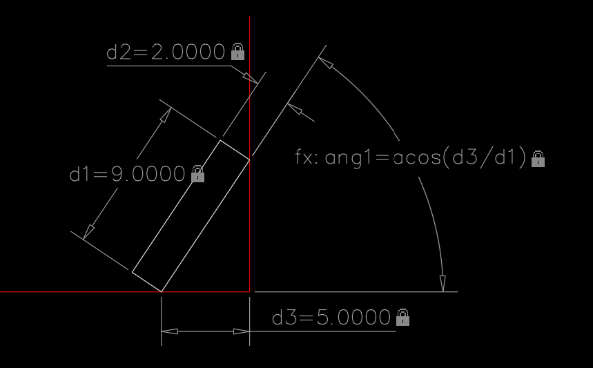
I thought I would have some more fun with this problem. As I posted earlier, I think AutoCAD's parametric features offer a good solution. Here's an easier construct. Open the attached file and go to the Parametric tab and click Show All or enter the command DCDISPLAY and select the box to see the dimensional constraints. Change the value of dimension d3 to see the box in a different position agaist the wall. The following VLISP program creates a box of user specified dimensions and animates it position and orientation as it slides along the floow and wall. 0,0 is assumed to be the lower corner of the wall. box_animation.mp4 ;Creates an animation of a rectangle slding along a floor ; as it rotates leaning agains a wall. ; 11/13/2026 (defun c:boxanimate (/ ang boxL boxW dAngle dAngleR p i d vlaObj nSteps dx) (vl-load-com) (setq boxL (getreal "\nEnter box length (9): ")) (if (not boxL) (setq boxL 9) ) (setq boxw (getreal "\nEnter box width (2) ")) (if (not boxW) (setq boxW 2) ) (setq dAngle 1 ; rotation angle increment ang dAngle ; total rotation dAngleR (/ (* pi dAngle) 180.) p (list (- boxL) 0) ; poit of rotation i 0 d 100 ; delay value ) (command "_rectangle" "_non" p "_non" (list 0 boxW)) (setq vlaObj (vlax-ename->vla-object (entlast))) (setq nSteps (/ 90 dAngle)) (setvar "CMDECHO" 0) (while (< i nsteps) (setq angR (/ (* pi ang) 180.)) (setq dx (abs (+ (car p) (* boxL (cos angR))))) (vla-Rotate vlaObj (vlax-3d-point p) dAngleR) (vla-Move vlaObj (vlax-3d-point '(0.0 0.0 0.0)) (vlax-3d-point (list dx 0.0 0.0)) ) (setq ang (+ ang dAngle) p (mapcar '+ p (list dx 0)) ) (vla-update (vlax-get-acad-object)) (command-s "_.REGEN") (command "_.DELAY" 100) (setq i (1+ i)) ) (setvar "CMDECHO" 1) (princ) ) ; end defun box fit.02.dwg
-
Managing tolerance stack-up in assemblies with multiple mating components
SLW210 replied to indiancad's topic in AutoCAD 3D Modelling & Rendering
That somewhat falls on the engineer/designer doesn't it? I follow (normally) GD&T and the use of LMC and MMC when necessary along with the tolerances per class of fit. If properly designed with the appropriate tolerances and machined within those tolerances, it should fit properly. I usually draw objects that have tolerances at the median of the size if the tolerance is ± if it is -0 or +0 I draw it at that size in general, but really depends on the parts and the LMC/MMC. Unless instructed differently, most items I just look in the books and go with snug fit or loose fit depending on the assembly. -
This should suffice: (defun sortlist ( l ) (vl-sort l (function (lambda ( a b / x y ) (while (and (setq x (car a)) (setq y (car b)) (equal x y 1e-8)) (setq a (cdr a) b (cdr b) ) ) (if (and x y) (< x y) (null x)) ) ) ) )
-
Managing tolerance stack-up in assemblies with multiple mating components
indiancad posted a topic in AutoCAD 3D Modelling & Rendering
When several machined components fit together in an assembly, even small dimensional variations can accumulate and affect the final fit. A drawing may show every individual component within its specified tolerance, yet the assembled parts may still create alignment problems or unwanted clearance. This becomes particularly challenging when dimensions are controlled independently rather than from a common functional datum. When checking tolerance stack-up in mechanical assemblies, do you prefer worst-case analysis, statistical tolerance analysis, or a direct measurement approach? How do you decide which method is appropriate for production? -
Lighting design tools for Autocad
indiancad replied to ammobake's topic in AutoCAD 2D Drafting, Object Properties & Interface
For this type of work, I would recommend DIALux evo rather than relying on an AutoCAD LISP routine. It supports DWG floor-plan imports, lighting fixture placement, and photometric calculations using manufacturer IES/LDT files. You can check illuminance levels, uniformity, and fixture arrangements against project requirements, then export the results and layouts. It is free to use, although fixture availability depends on the manufacturers supported. This would be much more practical for verifying lighting compliance than designing entirely inside AutoCAD. -
Lighting design tools for Autocad
AONE_LED replied to ammobake's topic in AutoCAD 2D Drafting, Object Properties & Interface
For a quick check of that spec, the lumen method is usually enough before you pick a tool. 50 fc is roughly 540 lux. Fixtures needed = (E x A) / (lumens x UF x LLF). With the work plane at 30" and the suspended ceiling at about 9', the cavity height is roughly 6'. Typical utilisation for a 2x2 LED troffer in a light-coloured room is 0.6 to 0.7, with a light loss factor of 0.8 to 0.85. At 2000 lm per fixture that works out to roughly one fixture per 25 to 30 sq ft, so check the result against the manufacturer's maximum spacing-to-mounting-height ratio. Then place the fixtures on a grid matching the ceiling tiles in the RCP.