All Activity
- Past hour
-

zwcad SHX Text Not Editable in PDF
BIGAL replied to CHAKRADHAR's topic in AutoCAD Drawing Management & Output
Just do a google you should be able to find a ISO.TTF font there are thousands of fonts out there. You open c:\Windows\fonts and drag the TTF onto it from memory. ISO3098B ? If your lucky some one may have one already. - Today
-
Vehicle Tracking - where to find details for vehicles
BIGAL replied to Adam - Inspire's topic in Autodesk Software General
Like a lot here just remember teaching your children how to drive, no did not crash into things, but went around a roundabout, hands everywhere trying to turn, change gears and me praying as we chugged out. -
 Dominic Chaulk joined the community
 -
 jr1996 joined the community
 -
Can you post a sample drawing with a block example of before & after? Add explanatory notes to the drawing so that we understand. From what I can understand of your goal I think Lee's code will work without modification.
-

zwcad SHX Text Not Editable in PDF
SLW210 replied to CHAKRADHAR's topic in AutoCAD Drawing Management & Output
I can do that most of the time with the OCR (Optical character recognition) in Adobe Acrobat Pro. I thought Foxit has an OCR. -
I did just try this out, to no avail. I'm thinking I may have to do a lot of learning to solve this problem. Currently I'm thinking it may work the best to piggyback off of Lee's code so that the structure is there, and add the capability that I want. How complex that will be, I have no clue, but I suspect that I'll be learning a lot.
-
Blocks are one of the most powerful productivity features in AutoCAD. They allow you to combine multiple objects into a single, reusable element, making your drawings cleaner, more consistent, and easier to manage. Whether you’re working with symbols, parts, detail views, or title blocks, blocks help you work faster and more accurately. In this final installment of the AutoCAD Foundation series, we’re exploring how to insert a block and more. What Is a Block? A block is a collection of one or more objects combined into a single object. Once created, that block can be inserted multiple times into a drawing as individual block references, all tied back to the same underlying definition. You’ll commonly see blocks used for items such as: Furniture and fixtures Mechanical or electrical symbols Standard parts and components Detail callouts and title blocks Examples of blocks Using blocks offers several key advantages. Blocks help maintain consistency across drawings by ensuring uniformity for repeated elements such as symbols, parts, and title blocks. They also make editing and placement faster, since blocks can be inserted, rotated, scaled, moved, and copied much more efficiently than working with individual objects. Any changes made by editing or redefining a block are applied instantly to all of its references in the drawing. You can also include data such as part numbers, costs, service, dates, and performance values to blocks. The data is stored in special objects called block attributes. Finally, using multiple block references instead of duplicating object geometry helps reduce overall drawing file size. How to Insert a Block There are four key items involved when inserting a block into a drawing. #1. Block Definition This data is stored in a drawing file or drawing template file in a non-graphical format. Block definitions can easily be created or imported from any drawing file. Multiple block definitions can be created in a drawing file. Note: Block definitions don’t always need to be created just in the drawing that they will be used. A drawing file itself can represent a block definition that can be shared with other designers and inserted into any open drawing file. #2. Block Reference When you insert a block, you specify which block definition to create an instance or block reference from. The graphics for the block reference are drawn based on the block definition. A drawing file can also be inserted into an open drawing, when this happens a block definition based on the geometry in model space of the drawing file being inserted is created in the target drawing and then a block reference is created. #3. Block Insertion or Base Point When you insert a block, you specify an insertion point for the block in the drawing. The insertion point is based on the block’s base point, this is the point of the block reference attached to your cursor. The base point is circled on the block below. Later, if you select a block that’s already been inserted, it displays a grip at the base point. You can easily move and rotate this block using this grip. #4. Block Insertion Tool Several different block insertion tools are available in AutoCAD including: Block gallery on the ribbon Blocks palette Tool Palettes window DesignCenter These block insertion tools allow you to insert block references from the definitions created within the current drawing as well as insert drawing files stored on your local workstation or a shared network location. See How to Insert a Block Keep Going Ready to try out how to insert a block for yourself? Check out the AutoCAD Foundations page with exercises to get started. The post How to Insert a Block: AutoCAD Foundations appeared first on AutoCAD Blog. View the full article
-
 cglacet joined the community
 -
 petchema joined the community
 -

zwcad SHX Text Not Editable in PDF
CyberAngel replied to CHAKRADHAR's topic in AutoCAD Drawing Management & Output
You may not have a choice here, but can you convert your text to TTF from SHX? PDF should accept that as text. -

AL's Steel Mill not working on BricsCAD
Clint replied to Jgrand3371's topic in AutoLISP, Visual LISP & DCL
This LISP routine works well up to the latest BricsCAD version as of this reply post date. Clint -
Do you have AutoSketch? What program are you using to make the cutting path? What file types can you save as or export? You may have to just redraw everything in a more compatible, newer CAD software. Many have a free trial. What compatibility mode are you running it in? You might try an older Windows in an older computer or a virtual box, if you feel that could be the issue.
-

Vehicle Tracking - where to find details for vehicles
Steven P replied to Adam - Inspire's topic in Autodesk Software General
Took the day yesterday to work through the examples, youtube and so on, a bit of trial and error and kid of got it working. Just need to practice more - it wasn't as bad as it looked at first Driving however is another thing. Still crashing into things. -
 karma dorji joined the community
 -
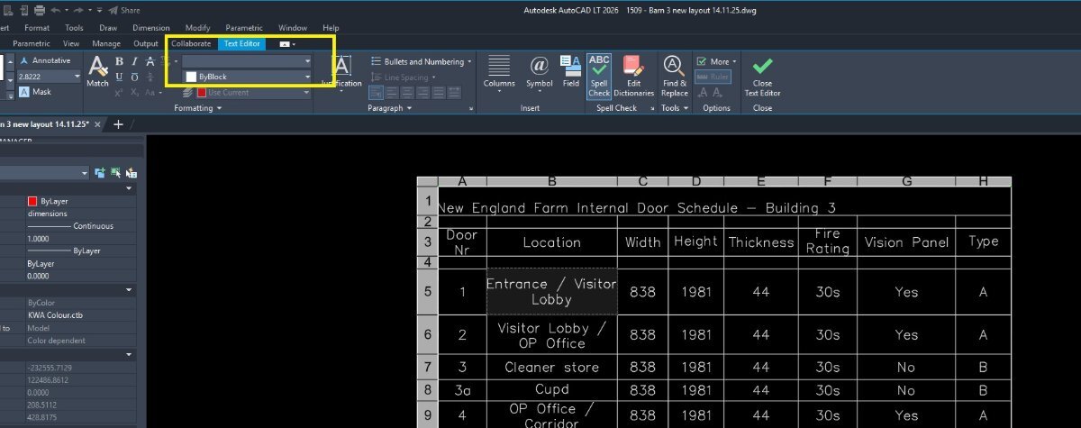
In ZWCAD 2026, our drawing uses isocp.shx font inside block attributes. When exporting to PDF, the SHX text is converted to geometry and becomes non-editable in Foxit. Is there any way to export SHX text as real editable text without changing the drawing font standard? text issue.dwg without sign 1.pdf
-
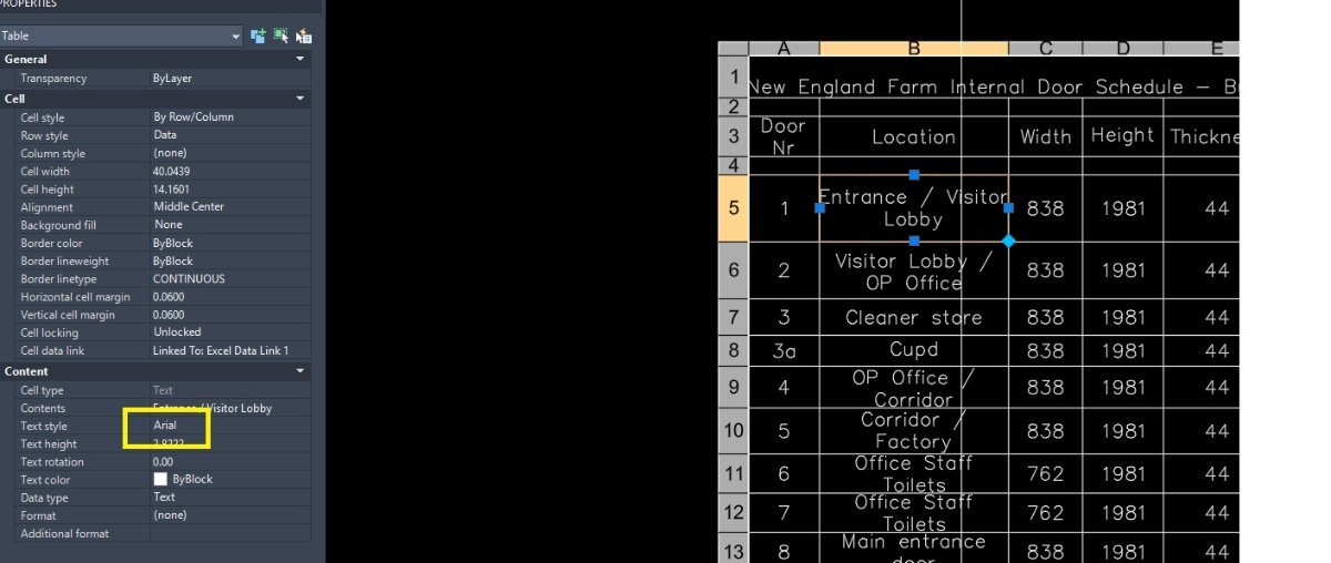
How to override text formatting
BIGAL replied to GrahamT's topic in AutoCAD 2D Drafting, Object Properties & Interface
You have a Table in your images, you can change all or one cell in a table with respect to the font style. Is that what your asking for ? If so post an example table dwg. Something like this (vla-SetTextStyle Objtable (+ acDataRow) "Arial") in a lisp. -
 JAIME_AC joined the community
 - Yesterday
-
Have you tried "CT*" when asked for block name in Lee's code. I don't have say multiple dwgs to test on. I don't see any real problem get all "INSERT"' then look for tag name if exist, change textstring. It's more about selecting dwg's to check. Will have a think about it.
-
 AndrewB joined the community
 -
I've created a guitar headstock logo in .SKF format, and it looks fine. However, when I convert it to .DXF and try to create a CNC cutting path it shows big gaps in the pattern. I've tried to work out where the lines aren't connecting by filling in pattern in sections, but the results are inconsistent. Sometimes a section will fill or two sections will fill individually, and then when I remove the barrier between them they no longer work. I'm using an older version on Windows 11, so I've read some things that suggest it might be a compatibility issue. Can anyone assist, or suggest a way for me to resolve this?
-
I guess that would be what I'm calling the unique identifier. with out seeing the block you might be able to hard code some of the push values. but I'm just using getstring. Push values to update blockname, attribute name, "CT-1", attribute name to update, updated value. in the first drawing. open second drawing or all drawings you want to update. Use command in first drawing to pass values to 2nd drawing. (vl-propagate) use update command in 2nd drawing to update value. (defun C:PushValues() (if (setq Blkname (getstring "Blkname: " T)) (vl-propagate 'blkname) ) (if (setq tag1 (getstring "TagName: " T)) (vl-propagate 'tag1) ) (if (setq tv1 (getstring "TagValue: " T)) (vl-propagate 'tv1) ) (if (setq tag2 (getstring "TagName: " T)) (vl-propagate 'tag2) ) (if (setq tv2 (getstring "Update String: " T)) (vl-propagate 'tv2) ) (princ) ) ;;----------------------------------------------------------------------------;; ;; Update Block's Attributes (defun c:SyncBlocks (/ SS) (if (and blkname tag1 tag2 tv1 tv2) (progn (if (setq SS (ssget "_X" (list (0 . "INSERT") (cons 2 blkname)))) (foreach blk (mapcar 'cadr (ssnamex ss)) (setq result 'getpropertyvalue (list blk tag1)) (if (eq result tv1) (setpropertyvalue blk tag2 tv2) ) ) ) ) (progn (princ "\nRun Push Values on master file") (princ "\nMissing Values") ) ) (princ) )
-
I'm beginning to understand that this is not a quick fix. Instead of using handles and entity names, is there a way to use the component tag? I don't really care what block I'm editing, I need to edit all of them that contain the same tag. I will see about getting a sample drawing set made up and post it here soon. To explain how it is setup in the mean time: Multiple drawings are used in one package, and use some of the same blocks, some different ones to represent the same physical component. (I didn't make the templates). Regardless, these components are unique in position, and are numbered as such. They all use the same/similar blocks. Say it is a current transformer, I could have CT-1 through CT-30 in one drawing. All of them would appear in multiple drawing files with different blocks, meaning every instance has a different handle. The current setup uses ACADE's native component linking through PTags, so that when I change an attribute of a block with the tag CT-1 in one drawing, it prompts me to update all other drawings in which that tag (not block) appears, or to add this update to the task list. This results in needing to edit the same information 30 times to update it, or a similar amount for each drawing using attout-attin. The goal is something much like attout, but done based on the component's tag, not on the handle. I may have a look at attout's code to see how it works, but I am very new to coding and am probably in over my head with this. Thank you for the help!
-
I don't think their is a quick fix for this. handles and entity names are created when you open the drawing and are never the same between drawings. this is what attout and attin use when updating block attributes. You essentially need to create a unique identifier attribute between drawings that link the same blocks. this would allow you to sync/update one type of block and one attribute at a time. or do it all in excel using one attout as the master list to pull from. attout all other drawings using xlookup back to the master. still would need a unique identifier attribute. would need to see a sample drawing and blocks you want to sync.
-
 saujan joined the community
 -
 L43977 joined the community
 -
How to override text formatting
SLW210 replied to GrahamT's topic in AutoCAD 2D Drafting, Object Properties & Interface
There are several LISP programs around for stripping MTEXT. Solved: strip mtext formatting - Autodesk Community Re: StripMText Issue - Autodesk Community In the MText Editor there is a down arrow on the top right, scroll down to Remove Formatting. -
 Dannytechpro89 joined the community
 -
I'm unsure how to do this as of now, but I will be looking into it. After playing with the program in ACADE, the way it works is what I want, it just doesn't do it as specifically as I'd like. I've got some learning to do, but I will be trying to adjust the code to work for me. I'm new to coding of any sort, so any advice on how to go about this would be greatly appreciated. Thank you for the pointer.
-

How to override text formatting
GrahamT posted a topic in AutoCAD 2D Drafting, Object Properties & Interface
Hello All I keep hitting a problem with text formatting which I just can't solve. When I double click on any MTEXT, it will show the text style as (for example) STANDARD, but when I change that in the properties dialog to (for example) ARIAL, nothing changes in the text style. I've found the only way to change it to the font you want is to go to the text formatting palette and manually change it there for each text item. See example below: You can see that in example2 I've changed the text style to ARIAL but the text remains as SIMPLEX. The only way I can change it is to double click then change it in the text formatting palette to ARIAL as shown in example1. This makes changing the text very cumbersome across a drawing. Please note, the example here happens to be in a table, but it happens outside of tables too. Surely there is a way to stop this happening and make the text change to what you want it to be? Any help greatly appreciated. GrahamT
- Last week
-

Need Information About Best Autocard Software For PC
tombu replied to angrythor's topic in Autodesk Software General
Once you find out what AutoCAD software you need for the type of work you do you need to check what System requirements that software needs: https://www.autodesk.com/support/system-requirements/overview You'll get more useful responses if you tell us what type of work you're trying to learn how to do and what educational and professional background you have. My experience is with Land Surveying and Civil Engineering. If you're in a different field I'm sure someone in your field would respond. -
Vehicle Tracking - where to find details for vehicles
tombu replied to Adam - Inspire's topic in Autodesk Software General
We used AutoTurn by Transoft for years as an AutoCAD plugin years before Vehicle Tracking or even Civil 2D was added to AutoCAD. It was a company in England at the time but it's worldwide now and no longer a simple AutoCAD plugin! -
As Lee's code is open you could look at what is going on, to see if it is possible to say do a block name "*" with tagname "Material". I did find this in Lee's code give it a try. "Please Enter a Block Name.\n\n" "Note: Block names are not case-sensitive and may use wildcard patterns" " to match multiple blocks containing the same attribute tag."
-
Vehicle Tracking - where to find details for vehicles
BIGAL replied to Adam - Inspire's topic in Autodesk Software General
Just remember with say a semi you have to turn outward before turning in the direction you want for tight corners, same with exit oversteer corner. It normally took say 3+ goes to get a smooth path. Followed a road train go through multiple roundabouts in Darwin, a road train is 3 x 19m trailers 66 ton. The driver would go left and right crossing 3 lanes but did not go slow, What was that bump ? -
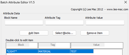
I don't understand what you are trying to do. I used the configuration below, with wildcard for any block named with "light", and set all attributes named with a tag of "MATERIAL" to have a value of "TEST". Worked perfectly on multiple drawings.