All Activity
- Past hour
-
 Pramod Kumar joined the community
- Today
-
 Alessandro joined the community
-
Associative Textbox (Lee Mac)
Alessandro replied to sachindkini's topic in AutoLISP, Visual LISP & DCL
Dear sir, on my autocad LT 2027, if i generate a TBOX and then i copy and paste the text (both using the command copy and using ctrl+c - ctrl+v), i don't have a copy of the tbox too. Is there a solution for this? -
 cristianrivera25 joined the community
-

Lighting Fixture Schedule - Best Practice
AONE_LED replied to lkenshalo's topic in AutoCAD 2D Drafting, Object Properties & Interface
For lighting schedules in vanilla AutoCAD, a fixture block with attributes plus DATAEXTRACTION is usually the most reliable method. Use a unique type mark (A, B, C) as an attribute at the insertion point, and add attributes for description, lumens, wattage, CCT, voltage, mounting (recessed, surface or pendant) and ceiling cut-out. Keep one block definition per fixture type so the counts stay accurate. DATAEXTRACTION can then build a table of Type, Description, Quantity, Watts and Lumens, and you can refresh it when the layout changes. Excel is still useful for photometric and driver data that does not live in the drawing; DATALINK the finished table back into the sheet so the two stay in step. Avoid mixing a hand-counted grid with extracted quantities, or the schedule will drift. -
Shaped light source - i.e., fluorescent light bulb
AONE_LED replied to SaigoLives's topic in AutoCAD 3D Modelling & Rendering
In AutoCAD 2000 you cannot declare a solid as a light source, and photometric weblights did not exist yet. Model each fluorescent as a simple 26 mm (T8) or 16 mm (T5) cylinder, then place a row of low-intensity point lights along the tube centreline at about 200–300 mm centres so the light is even. Give the tube a pale, slightly self-illuminated material so the lamp reads as glowing in the render; keep the housing as ordinary geometry so it can cast a soft shadow. For a ceiling grid, copy this fixture as a block to each troffer location and aim the lights downward. If you later move to AutoCAD 2007 or newer, set LIGHTINGUNITS to 2 (SI) and use one WEBLIGHT per fixture with a manufacturer IES file instead. -
displaying cove lighting in a relfected ceiling plan?
AONE_LED replied to bbestone's topic in AutoCAD Beginners' Area
Cove lighting on an RCP is usually shown as a continuous dashed or hidden line along the inside face of the cove, not as a row of downlight circles. Put it on its own layer, for example A-CLNG-LITE-COVE, so you can plot it lighter than the ceiling grid. If the cove has a linear LED or fluorescent strip, a single dashed line at the lamp position is enough; a narrow hatch or a double line can indicate a wider light shelf. Tag the run with the fixture type (for example "C1 – LED tape in cove") and note the soffit depth in the legend. Recessed downlights and the ceiling grid stay as solid symbols. Grey-tone RCPs are common: existing work in grey, new lighting and notes in black, all drawn at 1:1 in model space. - Yesterday
-

Managing tolerance stack-up in assemblies with multiple mating components
SLW210 replied to indiancad's topic in AutoCAD 3D Modelling & Rendering
Do you know GD&T? -

Dynamic block changes are not updating attribute values consistently
indiancad posted a topic in AutoCAD Drawing Management & Output
In projects that use dynamic blocks for equipment layouts, electrical symbols, or standard components, changing visibility states and block parameters can sometimes leave attribute information inconsistent across different block instances. This becomes particularly troublesome when drawings contain hundreds of instances with part numbers, descriptions, or equipment tags that must remain accurate. Commands such as ATTSYNC can synchronise attribute definitions, but they may also affect manually modified attribute values. How do you manage attribute consistency in drawings containing large numbers of dynamic block instances? Do you rely on ATTSYNC, custom AutoLISP routines, or a different block-management workflow? -
Need to export each solid as separate dwg, dxf or 3ds file format
indiancad replied to ADSK2007's topic in AutoLISP, Visual LISP & DCL
This can be automated using AutoLISP with the WBLOCK command. A routine can iterate through all 3DSOLID entities, export each one as a separate DWG, and generate sequential filenames such as Solid-001.dwg. One important detail is to distinguish between preserving the original world coordinates and moving each solid to 0,0,0. Which output do you need: original coordinates or each solid individually positioned at the origin? -
 bander4ik joined the community
-
Managing tolerance stack-up in assemblies with multiple mating components
indiancad replied to indiancad's topic in AutoCAD 3D Modelling & Rendering
Thanks for sharing your approach One concern is that even when individual parts meet their specified tolerances, tolerance accumulation can still create unexpected assembly issues. Do you also perform a tolerance stack-up analysis for critical assemblies, or do you rely mainly on fit classes and standard tolerances? -
Managing tolerance stack-up in assemblies with multiple mating components
indiancad replied to indiancad's topic in AutoCAD 3D Modelling & Rendering
. -
Need to export each solid as separate dwg, dxf or 3ds file format
AONE_LED replied to ADSK2007's topic in AutoLISP, Visual LISP & DCL
When you WBLOCK each solid, leave it at its real world coordinates and use a common base point of 0,0,0 for every file. If you move each solid to the origin before export, DIALux has no relative position left to rebuild the room. Keep the same units in AutoCAD and DIALux (metres is safest); a units mismatch is the usual reason imports appear in the wrong place even when the base point is consistent. Because you already have each solid on its own layer, naming the WBLOCK after the layer is fine. Prefer DWG over 3DS if evo will accept it, and lower FACETRES if the mesh is too heavy. After import, check one known corner against the original coordinates before you assign materials. -
Objects from straight polyline to spline
AONE_LED replied to Joe.'s topic in AutoLISP, Visual LISP & DCL
The existing WOW LISP copies each luminaire to the same distance along the new path, which is the right idea for uneven spacing. One important lighting detail: the routine inserts the block at rotation 0, so fittings will not turn with the curve. When you insert, set the rotation from the path tangent (the direction of the first derivative at that distance) so linear or wall-wash luminaires stay aligned to the run. Also confirm both polylines are measured from the same end; if they run in opposite directions the fixtures will be mirrored along the path. If the curved path is slightly shorter than the straight one, the last fitting may land on the end point — that is usually acceptable for a millimetre-level difference, but check the last spacing on a long street or cove run. -
Problem with IES Lighting particularly its source glow
AONE_LED replied to ThrashMetal's topic in Cameras, Lighting & Rendering
An IES web light only stores the far-field intensity distribution; it does not make the fixture geometry look like it is emitting. Keep the IES light for the room illumination, and give the lamp or diffuser a self-illuminated material (luminance in candelas per square metre) so the source itself glows in the render. Avoid adding a second spherical photometric light on top of the IES file, or you will roughly double the flux in the scene. If the downlight pattern only appears low on the wall, the IES is probably a narrow-beam or recessed cut-off distribution. Check that the web's nadir points straight down, place the light at the real ceiling height, and try a wider-beam IES if you want the scallop higher up the wall. -

Fitting without collision
Discus84 replied to Discus84's topic in AutoCAD 2D Drafting, Object Properties & Interface
Big thanks, this solves the problem nicely! - Last week
-
 Kais joined the community
-
 progeCAD USA joined the community
-
 ReviCAD Solutions LLP joined the community
-
 CADstart joined the community
-
 tungiml16 joined the community
-

Fitting without collision
lrm replied to Discus84's topic in AutoCAD 2D Drafting, Object Properties & Interface
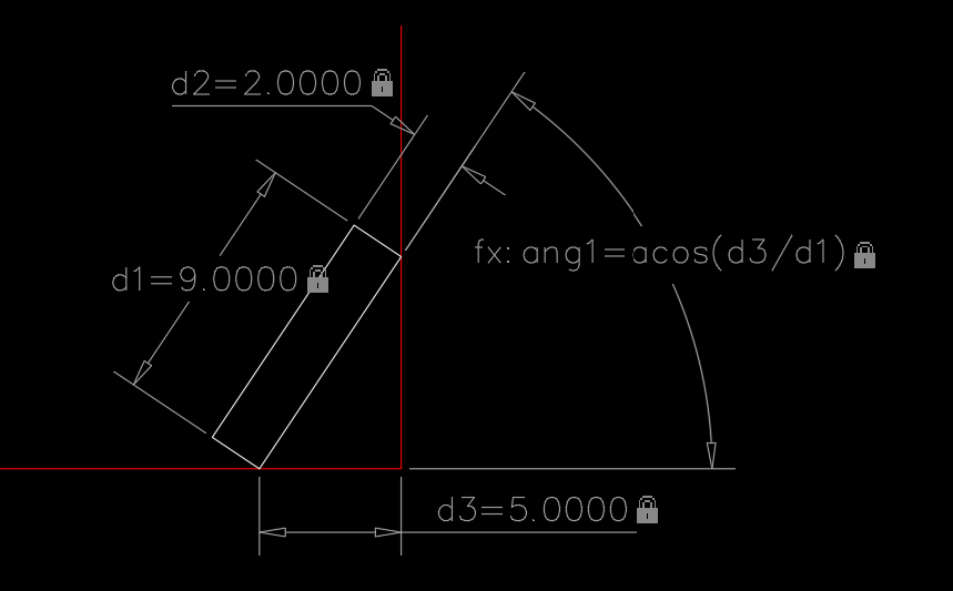
I thought I would have some more fun with this problem. As I posted earlier, I think AutoCAD's parametric features offer a good solution. Here's an easier construct. Open the attached file and go to the Parametric tab and click Show All or enter the command DCDISPLAY and select the box to see the dimensional constraints. Change the value of dimension d3 to see the box in a different position agaist the wall. The following VLISP program creates a box of user specified dimensions and animates it position and orientation as it slides along the floow and wall. 0,0 is assumed to be the lower corner of the wall. box_animation.mp4 ;Creates an animation of a rectangle slding along a floor ; as it rotates leaning agains a wall. ; 11/13/2026 (defun c:boxanimate (/ ang boxL boxW dAngle dAngleR p i d vlaObj nSteps dx) (vl-load-com) (setq boxL (getreal "\nEnter box length (9): ")) (if (not boxL) (setq boxL 9) ) (setq boxw (getreal "\nEnter box width (2) ")) (if (not boxW) (setq boxW 2) ) (setq dAngle 1 ; rotation angle increment ang dAngle ; total rotation dAngleR (/ (* pi dAngle) 180.) p (list (- boxL) 0) ; poit of rotation i 0 d 100 ; delay value ) (command "_rectangle" "_non" p "_non" (list 0 boxW)) (setq vlaObj (vlax-ename->vla-object (entlast))) (setq nSteps (/ 90 dAngle)) (setvar "CMDECHO" 0) (while (< i nsteps) (setq angR (/ (* pi ang) 180.)) (setq dx (abs (+ (car p) (* boxL (cos angR))))) (vla-Rotate vlaObj (vlax-3d-point p) dAngleR) (vla-Move vlaObj (vlax-3d-point '(0.0 0.0 0.0)) (vlax-3d-point (list dx 0.0 0.0)) ) (setq ang (+ ang dAngle) p (mapcar '+ p (list dx 0)) ) (vla-update (vlax-get-acad-object)) (command-s "_.REGEN") (command "_.DELAY" 100) (setq i (1+ i)) ) (setvar "CMDECHO" 1) (princ) ) ; end defun box fit.02.dwg
-
Managing tolerance stack-up in assemblies with multiple mating components
SLW210 replied to indiancad's topic in AutoCAD 3D Modelling & Rendering
That somewhat falls on the engineer/designer doesn't it? I follow (normally) GD&T and the use of LMC and MMC when necessary along with the tolerances per class of fit. If properly designed with the appropriate tolerances and machined within those tolerances, it should fit properly. I usually draw objects that have tolerances at the median of the size if the tolerance is ± if it is -0 or +0 I draw it at that size in general, but really depends on the parts and the LMC/MMC. Unless instructed differently, most items I just look in the books and go with snug fit or loose fit depending on the assembly. -
This should suffice: (defun sortlist ( l ) (vl-sort l (function (lambda ( a b / x y ) (while (and (setq x (car a)) (setq y (car b)) (equal x y 1e-8)) (setq a (cdr a) b (cdr b) ) ) (if (and x y) (< x y) (null x)) ) ) ) )
-
Managing tolerance stack-up in assemblies with multiple mating components
indiancad posted a topic in AutoCAD 3D Modelling & Rendering
When several machined components fit together in an assembly, even small dimensional variations can accumulate and affect the final fit. A drawing may show every individual component within its specified tolerance, yet the assembled parts may still create alignment problems or unwanted clearance. This becomes particularly challenging when dimensions are controlled independently rather than from a common functional datum. When checking tolerance stack-up in mechanical assemblies, do you prefer worst-case analysis, statistical tolerance analysis, or a direct measurement approach? How do you decide which method is appropriate for production? -
Lighting design tools for Autocad
indiancad replied to ammobake's topic in AutoCAD 2D Drafting, Object Properties & Interface
For this type of work, I would recommend DIALux evo rather than relying on an AutoCAD LISP routine. It supports DWG floor-plan imports, lighting fixture placement, and photometric calculations using manufacturer IES/LDT files. You can check illuminance levels, uniformity, and fixture arrangements against project requirements, then export the results and layouts. It is free to use, although fixture availability depends on the manufacturers supported. This would be much more practical for verifying lighting compliance than designing entirely inside AutoCAD. -
Lighting design tools for Autocad
AONE_LED replied to ammobake's topic in AutoCAD 2D Drafting, Object Properties & Interface
For a quick check of that spec, the lumen method is usually enough before you pick a tool. 50 fc is roughly 540 lux. Fixtures needed = (E x A) / (lumens x UF x LLF). With the work plane at 30" and the suspended ceiling at about 9', the cavity height is roughly 6'. Typical utilisation for a 2x2 LED troffer in a light-coloured room is 0.6 to 0.7, with a light loss factor of 0.8 to 0.85. At 2000 lm per fixture that works out to roughly one fixture per 25 to 30 sq ft, so check the result against the manufacturer's maximum spacing-to-mounting-height ratio. Then place the fixtures on a grid matching the ceiling tiles in the RCP. -

Aluminum composite panels parametric templates
BIGAL replied to emosms's topic in AutoCAD 2D Drafting, Object Properties & Interface
@emosms did you give it a try ? It is only a very early start in the coding just a show how it could be done. -
You should have said at the 1st post want to sort up to 5 items deep in a list. I had this task for something else I did. Hopefully this is a dummy of what your after. it is amost instant to make 10000 items and sort them. I apoligise I forget where I got the complex sort from regarding authors name. ; sort on up to 5 items in sub lists ; By AlanH (defun compare-elements (a b sortspec) ((lambda (x y test) (if (and (equal x y ) (cdr sortspec)) (compare-elements a b (cdr sortspec)) (apply test (list x y)) ) ) (nth (cdar sortspec) a) (nth (cdar sortspec) b) (caar sortspec) ) ) (defun complex-sort (alst sortspec) (vl-sort alst '(lambda (a b) (compare-elements a b sortspec) ) ) ) ;; Rand - Lee Mac ;; PRNG implementing a linear congruential generator with ;; parameters derived from the book 'Numerical Recipes' (defun LM:rand ( / a c m ) (setq m 4294967296.0 a 1664525.0 c 1013904223.0 $xn (rem (+ c (* a (cond ($xn) ((getvar 'date))))) m) ) (/ $xn m) ) ;; Random in Range - Lee Mac ;; Returns a pseudo-random integral number in a given range (inclusive) (defun LM:randrange ( a b ) (+ (min a b) (fix (* (LM:rand) (1+ (abs (- a b)))))) ) (defun wow ( / ) (setq lst '()) (repeat 10000 (setq v1 (atoi (rtos (LM:randrange 1 1000 ) 2 0))) (setq v2 (atof (rtos (LM:randrange 1 1000 ) 2 3))) (setq v3 (atof (rtos (LM:randrange 1 1000 ) 2 3))) (setq v4 (atof (rtos (LM:randrange 1 1000 ) 2 3))) (setq v5 (atof (rtos (LM:randrange 1 1000 ) 2 3))) (setq lst (cons (list v1 v2 v3 v4 v5) lst)) ) (setq numcols (length (car lst))) (cond ((= numcols 1)(setq lst (complex-sort lst '((< . 0))))) ((= numcols 2)(setq lst (complex-sort lst '((< . 0) (< . 1))))) ((= numcols 3)(setq lst (complex-sort lst '((< . 0) (< . 1) (< . 2))))) ((= numcols 4)(setq lst (complex-sort lst '((< . 0) (< . 1) (< . 2)(< . 3))))) ((= numcols 5)(setq lst (complex-sort lst '((< . 0) (< . 1) (< . 2)(< . 3)(< . 4))))) ((> numcols 5)(setq lst (complex-sort lst '((< . 0) (< . 1) (< . 2)(< . 3)(< . 4))))) ) (princ) ) (wow)
-
I would strongly advise against using that bubblesort function, it is horribly inefficient. (vl-sort)/(vl-sort-i) both use a version of quicksort (one of the fastest sorting algorithms), implemented in C++; as such, they will always outperform any other sorting algorithm implemented using the LISP API. If the subset is known prior to sorting then sort only the subset (since the sort is the heaviest operation); else you have no choice but to take the subset following the sort.
-
@BIGAL Thanks. I've tried Bubblesort and it seems to work well. But won't the recursive call to Bubblepass be problematic with very long lists? I've run into this problem a couple of times while doing my tests. Thank you very much, @Lee Mac I didn't know about vl-sort-i until now. After trying it, I think it's the best solution. The only drawback is that it always returns the full list of indices even though the user might only need a smaller number of elements. However, it works very fast even with very large lists, so this isn't a problem. By the way: my lists consist of lists of 5 numbers: 1 integer and 4 real numbers, which I need to sort from lowest to highest and with a preference order from left to right.
-
Yes, could be a good thing or a bad thing depending on what PGia wants to do. like I wouldn't use the entity name as the key as they are generated when opening the drawing and would be invalid next time you open said drawing. Also I think you can only store strings in the dotted pair. was only bringing as another option for a faster search of a "list".
-
Stating the obvious: just consider that creating xrecords & dictionaries is modifying the drawing database and the data is stored in the drawing, whereas LISP data is obviously transient.