All Activity
- Past hour
-
Added a little on the front end to wrap it all in one command with user input options. Should display something like this Change_Prec or CP Enter "C" for Custom Values Choose Percision From:To : [1:2 1:3 2:1 2:3 3:1 3:2]: 3:2 Changing Select MText Precision From [3] to [2] ... -Edit Updated it so you can just type "Change_Prec 3 2" and skip all that and just start asking you to make a selection. change_prec_fields_update.lsp
- Today
-
I already tried it, but something strange happens: it filters the 3D solids, but it puts the other elements at z=1.0000E+99
-
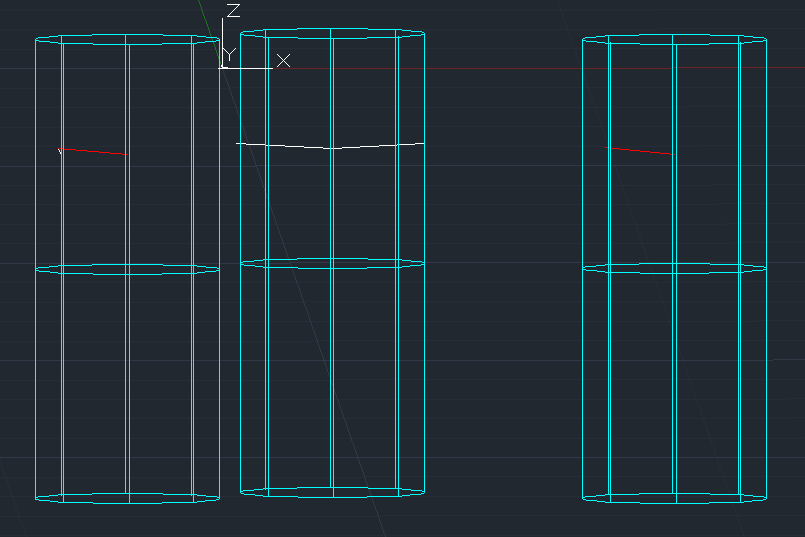
 I’m working on an AutoCAD .NET (C#) command that creates two Solid3d cylinders (one in +Z and one in –Z direction) starting from a selected point on an insulator line. Each cylinder is created with CreateFrustum, then moved into place using TransformBy(Matrix3d.Displacement) and optionally rotated around the point. However, I’ve run into a strange issue: sometimes the cylinders appear exactly in the correct place, but sometimes they shift several meters away from the point. In some cases both cylinders stack on each other, even though they should be separated along the Z-axis. The LIST command occasionally shows bounding boxes like: X = [-3500, 3500] Y = [-3500, 3500] Z = [-5000, 5000] which means the cylinder was never displaced at all, even though I definitely applied the transform. Here is the code that draws the cylinders: private void DrawClearanceCylinders(Database db, Editor ed, IEnumerable<Point3d> centers, double radius, double angleDeg) { if (centers == null) return; double h = CYL_LENGTH; double angRad = angleDeg * Math.PI / 180.0; using (var tr = db.TransactionManager.StartTransaction()) { var bt = (BlockTable)tr.GetObject(db.BlockTableId, OpenMode.ForRead); var btr = (BlockTableRecord)tr.GetObject( bt[BlockTableRecord.ModelSpace], OpenMode.ForWrite); foreach (var c in centers) { Solid3d cylUp = new Solid3d(); cylUp.SetDatabaseDefaults(); cylUp.CreateFrustum(h, radius, radius, radius); cylUp.TransformBy(Matrix3d.Displacement( new Vector3d(c.X, c.Y, c.Z))); if (Math.Abs(angleDeg) > 1e-6) cylUp.TransformBy(Matrix3d.Rotation(angRad, Vector3d.XAxis, c)); btr.AppendEntity(cylUp); tr.AddNewlyCreatedDBObject(cylUp, true); Solid3d cylDown = new Solid3d(); cylDown.SetDatabaseDefaults(); cylDown.CreateFrustum(h, radius, radius, radius); cylDown.TransformBy(Matrix3d.Displacement( new Vector3d(c.X, c.Y, c.Z - h))); if (Math.Abs(angleDeg) > 1e-6) cylDown.TransformBy(Matrix3d.Rotation(angRad, Vector3d.XAxis, c)); btr.AppendEntity(cylDown); tr.AddNewlyCreatedDBObject(cylDown, true); } tr.Commit(); } } The logic seems correct: create → displace → rotate → add to model space. But the result is inconsistent, and sometimes the displacement appears to be ignored. I’m trying to understand whether: CreateFrustum has an internal origin/transform I’m not accounting for the rotation around point c is interfering with the placement Solid3d requires a different transform order or if there’s a known issue with Solid3d placement after creation If anyone has experience with placing Solid3d cylinders precisely at a specific point, or knows what could cause the transforms to behave inconsistently, I’d really appreciate your insight. Command: LIST 6 found 3DSOLID Layer: "clerance_zone" Space: Model space Color: 4 (cyan) Linetype: "CONTINUOUS" Handle = 1000070 History = None Show History = No Bounding Box: Lower Bound X = 16294.5100, Y = 28025.7321, Z = -20484.5100 Upper Bound X = 24294.5100, Y = 36025.7321, Z = -10484.5100 3DSOLID Layer: "clerance_zone" Space: Model space Color: 4 (cyan) Linetype: "CONTINUOUS" Handle = 100006f History = None Show History = No Bounding Box: Lower Bound X = 16294.5100, Y = 28025.7321, Z = -10484.5100 Upper Bound X = 24294.5100, Y = 36025.7321, Z = -484.5100 3DSOLID Layer: "clerance_zone" Space: Model space Press ENTER to continue: Color: 4 (cyan) Linetype: "CONTINUOUS" Handle = 100006e History = None Show History = No Bounding Box: Lower Bound X = 1484.5100, Y = 32991.0000, Z = -20484.5100 Upper Bound X = 9484.5100, Y = 40991.0000, Z = -10484.5100 3DSOLID Layer: "clerance_zone" Space: Model space Color: 4 (cyan) Linetype: "CONTINUOUS" Handle = 100006d History = None Show History = No Bounding Box: Lower Bound X = 1484.5100, Y = 32991.0000, Z = -10484.5100 Upper Bound X = 9484.5100, Y = 40991.0000, Z = -484.5100 3DSOLID Layer: "clerance_zone" Space: Model space Color: 4 (cyan) Linetype: "CONTINUOUS" Handle = 100006c History = None Show History = No Thanks!
-

Help with 3D spur gear drawing (no tooth width given) !!
CyberAngel replied to Nlevismith95's topic in AutoCAD 3D Modelling & Rendering
Unfortunately, a lot of courses try to teach you to read plans as well as draw them. The information seems to be there, but you have to puzzle it out. One element of the tooth has two points of tangency and a radius. Once you draw that arc, you have the point of intersection with the outside radius. The outer width of the tooth is almost irrelevant to the design, because it's the last piece. The most important dimension seems to be the pitch, because that's where the teeth meet. Mechanical isn't really my field, so someone else will probably be able to give you better information. -
I have made several versions of the change_prec.lsp code. Maybe it will be useful to someone. Changing the precision of several fields =========================================================== change_prec_1-2.lsp === changing the precision of the fields from 1 to 2 change_prec_1-3.lsp === changing the precision of the fields from 1 to 3 change_prec_2-1.lsp === changing the precision of the fields from 2 to 1 change_prec_2-3.lsp === changing the precision of the fields from 2 to 3 change_prec_3-1.lsp === changing the precision of the fields from 3 to 1 change_prec_3-2.lsp === changing the precision of the fields from 3 to 2 =========================================================== change_prec_fields.lsp
-
 tayyar joined the community
 -
Nice test @PGia, thanks! For some reason I didnt consider closed polylines in the _checkOffset function, so I added an extra check there. Should work as expected now: Not sure about the short corner. The lines are so narrow the centerline is pushed back out of the point. Seems to be logical to me but it does feel intuitive. Narrow indents don't get much love from the centerline. So "inlets" don't have enough influence on the shape of the line. What would the expected result be? Below makes sense since there is not enough space to go into the indent. Or are you maybe something like this where the line splits and goes into the hole:
-
Here is the button macro for selected objects, so something like BIGAL's recommendation should work. ^C^C_SELECT;_MOVE;0,0,0;0,0,1e99;_MOVE;P;;0,0,0;0,0,-1e99;
-
@Tsuky thank you very much, your code changes the precision of the fields from 2 to 1. I replaced 2 lines in the code to change the precision from 1 to 2. (if (setq nbs (vl-string-search "%pr2" value_string (setq tmp_nbs nbs))) (setq value_string (vl-string-subst "%pr1" "%pr2" value_string tmp_nbs) * * * * * * * * * * * * * * * * (if (setq nbs (vl-string-search "%pr1" value_string (setq tmp_nbs nbs))) (setq value_string (vl-string-subst "%pr2" "%pr1" value_string tmp_nbs) * * * * * * * * * * * * * * * * You've been very helpful!
-

Help Appreciated: Force Existing Layer Names to UPPER CASE Not Working
Saxlle replied to Clint's topic in AutoLISP, Visual LISP & DCL
You're welcome @Clint . Yes, the DCL file are not necessary every time, but it can be helpful and user-friendly to accomplish desired result (like this one from an example video from above) if you have multiple choosing (for eg. buttons or check-boxes for Uppercase, Lowercase, Renaming, etc.). Best regards. -
You can try this. (vl-load-com) (defun c:change_prec ( / ss AcDoc Space n ename Obj value_string nbs tmp_nbs) (princ "\nSelect MText.") (while (null (setq ss (ssget (list '(0 . "*TEXT") (cons 67 (if (eq (getvar "CVPORT") 1) 1 0)) (cons 410 (if (eq (getvar "CVPORT") 1) (getvar "CTAB") "Model")) ) ) ) ) (princ "\nAren't MText or Text!") ) (setq AcDoc (vla-get-ActiveDocument (vlax-get-acad-object)) Space (if (= 1 (getvar "CVPORT")) (vla-get-PaperSpace AcDoc) (vla-get-ModelSpace AcDoc) ) ) (vla-startundomark AcDoc) (repeat (setq n (sslength ss)) (setq ename (ssname ss (setq n (1- n))) Obj (vlax-ename->vla-object ename) ) (setq value_string (vla-FieldCode Obj) nbs 0) (cond ((eq (substr (vla-FieldCode Obj) 1 3) "%<\\") (while nbs (if (setq nbs (vl-string-search "%pr2" value_string (setq tmp_nbs nbs))) (setq value_string (vl-string-subst "%pr1" "%pr2" value_string tmp_nbs) nbs (1+ nbs) ) ) ) (vlax-put Obj 'TextString value_string) ) ) ) (vla-endundomark AcDoc) (prin1) )
-
Hi BIGAL, Your point is well received! Best regards, Clint Hill
-

Help Appreciated: Force Existing Layer Names to UPPER CASE Not Working
Clint replied to Clint's topic in AutoLISP, Visual LISP & DCL
Hi Gentlemen, Your code contributions for my learning is greatly appreciated! Hi Saxlle, I thank you for the nice video demonstration as well as the excellent program. It appears that my focus should be more on Visual LISP along with including the Dialog box code within the main program file. Best regards, Clint Hill -
Help Appreciated: Force Existing Layer Names to UPPER CASE Not Working
Saxlle replied to Clint's topic in AutoLISP, Visual LISP & DCL
Maybe this kind of solution can be interesting (to use a multiple selection, use Shift+Left mouse click, to use a single selection, use CTRL+Left mouse click): ; ************************************************************************** ; Functions : CHRENLAYERS ; Description : Select Layers To Change It To UPPERCASE Or LOWERCASE ; Author : SAXLLE ; Date : December 04, 2025 ; ************************************************************************** (prompt "\nSelect Layers To Change It To UPPERCASE Or LOWERCASE!\nTo run a LISP type: CHRENLAYERS") (princ) (defun c:CHRENLAYERS ( / old_echo dcl_id fname fn laylist lay items rval acad name) (vl-load-com) (setq old_echo (getvar 'cmdecho)) (setvar 'cmdecho 0) (create_dialog) (collect_layers) (setq dcl_id (load_dialog fname)) (if (not (new_dialog "Laylist" dcl_id)) (exit) ) (action_tile "cancel" "(cancel)") (start_list "ls") (mapcar 'add_list laylist) (end_list) (action_tile "ps1" "(read_items) (to_uppercase)") (action_tile "ps2" "(read_items) (to_lowercase)") (start_dialog) (unload_dialog dcl_id) (vl-file-delete fname) (gc) (princ) ) (defun cancel () (done_dialog 0) (terpri) (prompt "Application running were finished...") (princ) ) (defun collect_layers () (setq laylist (list) lay (tblnext "LAYER" T) ) (while lay (if (not (equal (cdr (assoc 2 lay)) "0")) (setq laylist (cons (cdr (assoc 2 lay)) laylist) lay (tblnext "LAYER") ) (setq lay (tblnext "LAYER")) ) ) (setq laylist (vl-sort laylist '<)) ) (defun read_items () (setq acad (vla-get-activedocument (vlax-get-acad-object))) (setq items (get_tile "ls") rval (mapcar '(lambda (x) (nth x laylist)) (read (strcat "(" items ")"))) ) ) (defun to_uppercase () (foreach item rval (setq name (strcase item)) (vla-SendCommand acad (strcat "-RENAME LA " item (chr 13) name (chr 13))) (prompt (strcat "\nThe layer " item " were changed into the UPPERCASE!")) (setvar 'cmdecho old_echo) (princ) ) (done_dialog 1) ) (defun to_lowercase () (foreach item rval (setq name (strcase item T)) (vla-SendCommand acad (strcat "-RENAME LA " item (chr 13) name (chr 13))) (prompt (strcat "\nThe layer " item " were changed into the LOWERCASE!")) (setvar 'cmdecho old_echo) (princ) ) (done_dialog 1) ) (defun create_dialog () (setq fname (vl-filename-mktemp "Laylist.dcl") fn (open fname "w") ) (write-line "Laylist :dialog { label = \"Select layers to change it to UPPERCASE or LOWERCASE!\"; :list_box { key = \"ls\"; multiple_select = true; height = 10; width = 50; } :row { :button { label = \"Change to UPPERCASE >>\"; key = \"ps1\"; fixed_width = true; } :button { label = \"Change to LOWERCASE >>\"; key = \"ps2\"; fixed_width = true; } :button { label = \"Cancel\"; key = \"cancel\"; mnemonic = \"C\"; alignment = centered; fixed_width = true; is_cancel=true; } } }" fn) (close fn) ) Also, you can see the short video example of how it works. CHRENLAYERS.mp4 Best regards. -
The fields are in the text, not in the block. The sample fields.dwg is attached in the first post. The problem is that you need to change the accuracy of several fields at the same time.
-
If you can identify where the field strings are then you could update them, you can look for say "AcExpr" in the string then replace pr1. Maybe use Bedit and Attsync to update blocks. Similar for Mtext. So where are they ? Provide a sample dwg, You should be able to do something by now look at (Vlax-get obj 'textstring)
-
It would be best to start a new post asking questions about making layers. Me like many others have defuns to make layers on the fly. If you describe what your trying to do I expect a quick response. Admin please move post.
-

cui panel image
mohammadreza replied to mohammadreza's topic in The CUI, Hatches, Linetypes, Scripts & Macros
yes, they are true . In other versions of AutoCAD, everything works properly, but I need to share my CUI and I cannot require everyone to use a single AutoCAD version. -
I have dozens of fields that need to be changed the precision. It will take a long time to edit each field...
-
Gentlemen, I must try to interpret each of your generous examples. These are very involved lines of code to this (older) novice. I will study CHAR as it appears to be key to text case definitions. Clint P.S.: Have any here heard of, used or now use the tried and true 20+ year old LAYECREATOR.LSP program?
- Yesterday
-
Might as well join the party, yes easy task, but missing. is co-ords to be labelled in some way so know which co-ords match which point.. Need you to post a proper dwg with desired table all set up, text height, column widths and so on.
-
@dexus Your animations are really original although I don’t think I managed to see exactly the same thing you showed in your video. But that doesn’t matter. Today I had the whole afternoon free, and I decided to try to “stress-test” your code. I drew several irregular margins and also tried to draw something resembling a “inlet” like the ones GLAVCVS mentions. However, the result was very consistent. In no case was it possible to make the centerline “lose orientation.” It only failed in the case of closed margins, as shown in the attached image. But I assume this happens because you didn’t consider that possibility, given the context of the rest of my examples. Also, there are a few minor details in some wide curves where the centerline clearly drifts away from the middle. Overall, the result is EXCELLENT. Regarding the “inlets” that @GLAVCVS mentions, I suppose it would be great to have a tool capable of robustly handling those cases. But, normally, these situations only occur in a few places and can be handled manually. In any case, a tool like that would definitely put its author’s name on the map. PS: I've attached the drawing of the image. AxisExple3.dwg
-

Help Appreciated: Force Existing Layer Names to UPPER CASE Not Working
BIGAL replied to Clint's topic in AutoLISP, Visual LISP & DCL
removed -
It could be as simple as changing "all" to "ss", where ss is a selection set. I am no expert on setting the exclude objects in a selection set. try this not really tested. (setq ss (ssget "_X" '((-4 . "<NOT") (0 . "3DSOLID") (-4 . "NOT>")))) or _move;(setq ss (ssget "_X" '((-4 . "<NOT") (0 . "3DSOLID") (-4 . "NOT>"))));;0,0,0;0,0,1e99;_move;ss;;0,0,0;0,0,-1e99
-
As above, need more information as where the data is coming from and how you want the LISP to run. The one I use "EOLA", "EOLB" (End "A" of line and End "B" of line) I run by pick line, pick text to replace - having created the template before hand (well, LISP does that). Might be you want the coordinates of circles and the table to be created in the order you select them, or ordered left to right, right to left, so could do with a bit more to work with.
-
"pr2" is precision - here 2 places, "pr1" at the end of the first expression is 1 decimal place