All Activity
- Past hour
-

Polyline Elevation Propertie in UCS
Oscar Fuentes replied to Oscar Fuentes's topic in AutoCAD 3D Modelling & Rendering
The image...
-
Polyline Elevation Propertie in UCS
Oscar Fuentes replied to Oscar Fuentes's topic in AutoCAD 3D Modelling & Rendering
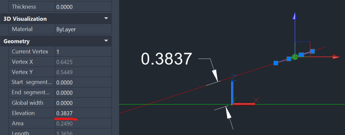
In the attached DWG file, a truncated pyramid was drawn with a unit of constants (UCS) on each face. The elevation of one of the polylines is 92.8477 and the other is 0.00, which does not correspond to the observations.
- Today
-

Polyline Elevation Propertie in UCS
lrm replied to Oscar Fuentes's topic in AutoCAD 3D Modelling & Rendering
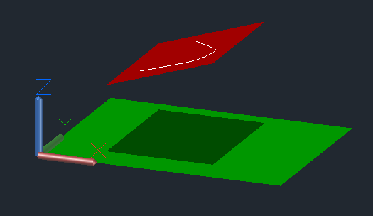
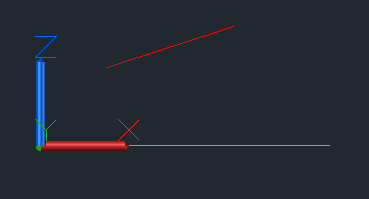
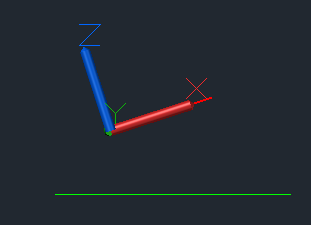
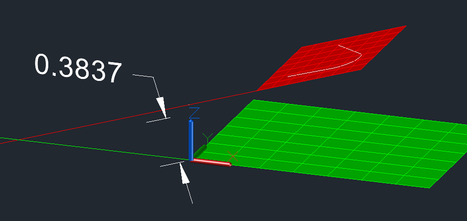
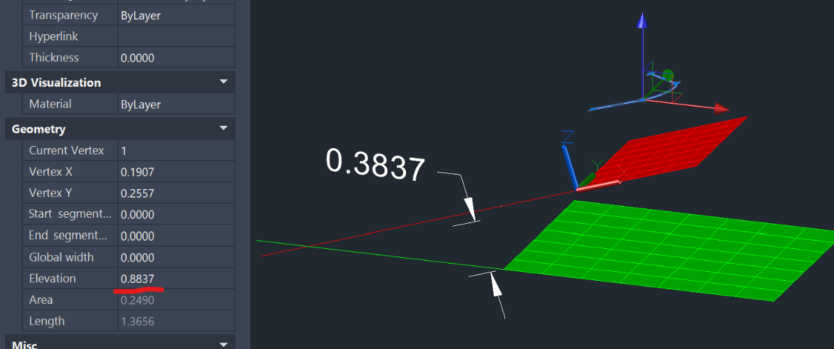
In the following image the green plane lies on the World XY plane while the red plane is above it and tilted. The white polyline was drawn on the red plane by setting the ucs so that it's Xand Y axes were coincident with it. Here's a front view with the World ucs active. Same view but with the UCS of the red plane active. The perpendicular distance from the plane of the polyline to World (0,0,0) is the polyline's elevation. Note that if the polyline is moved by 0.5 in the z direction of the red plane the elevation changes by 0.5. So the anser to the question "Can I change a polyline in my new coordinate system so that it has an elevation that conforms with the World system?" is, It Depends. The UCS of the polyline must be parallel to the world ucs but you would need to also make it coincident to the World UCS!
-
 osadamha joined the community
 -

CAD Files: Understanding, Managing, and Converting CAD Files
The AutoCAD Blog posted a topic in AutoCAD Blogs
Introduction to CAD Files In today’s digital world, CAD files, short for Computer-Aided Design files, are at the heart of how we design, draft, and build everything from skyscrapers to smartphones. These files contain precise technical drawings and 3D models that guide design decisions, manufacturing processes, and construction workflows. First developed in the 1960s as a way to move beyond hand-drawn blueprints, CAD technology has evolved into an essential tool that powers modern engineering, architecture, and product design. CAD files come in many formats, each designed for specific applications and software. For example, DWG files are widely used for detailed 2D and 3D drawings in AutoCAD, while DXF files offer greater compatibility for sharing designs between different programs. Understanding these formats and ensuring your files are compatible across platforms is crucial for seamless collaboration and efficient workflows. From architecture and construction to manufacturing and aerospace, CAD files play a vital role in bringing ideas to life. Architects use them to draft floor plans and elevations; engineers rely on them to model complex systems; manufacturers convert CAD models into instructions for machines. In short, CAD files form the digital backbone of design and documentation across industries worldwide. Working with CAD Files Creating CAD Files Creating a CAD file starts with choosing the right software for your project’s needs. Popular tools like AutoCAD, Revit, and Fusion allow designers, architects, and engineers to draft precise 2D drawings or build complex 3D models. The core components of a CAD drawing typically include lines, shapes, curves, and dimensions, which together define the geometry of a design. CAD files often also contain annotations, layers, and metadata, critical details that guide production, construction, or assembly. These elements make CAD files not just drawings, but rich data sets that communicate intent clearly across teams and disciplines. Managing CAD Files Given the complexity and size of many CAD projects, proper file management is essential. Best practices include organizing files into clearly labeled folders, using consistent naming conventions, and storing backups in secure, centralized locations (like cloud storage or company servers). Version control is particularly important in collaborative environments. Keeping track of revisions, whether through manual file versioning or using tools like a Common Data Environment (CDE) or Product Data Management (PDM) system, helps teams avoid costly errors and ensures everyone is working from the most current design. Sharing CAD Files Sharing CAD files with clients, contractors, or consultants requires more than just sending an email attachment. Depending on the file size and sensitivity, teams might use cloud-based platforms, secure file transfer services, or dedicated project management systems that support CAD files. Establishing clear workflows, like defining file formats for exchange (e.g., DWG, DXF, or PDF) and setting communication protocols, keeps collaboration efficient and reduces the risk of miscommunication. Especially on complex projects, these practices help ensure that design intent is preserved from concept through to construction or manufacturing. AutoCAD and AutoCAD LT: Industry-Leading CAD Solutions Overview of AutoCAD and AutoCAD LT When it comes to computer-aided design, AutoCAD and AutoCAD LT stand out as industry benchmarks. Both solutions are developed by Autodesk and offer powerful tools for creating, editing, and managing CAD files. AutoCAD provides a full-featured design environment with robust 2D drafting and 3D modeling capabilities, advanced automation tools, and support for custom extensions via APIs and add-ons. AutoCAD LT, on the other hand, is a streamlined version focused on 2D drafting and documentation, offering core functionality at a more affordable price point. Both platforms feature intuitive interfaces, precise dimensioning tools, annotation features, and layer management systems that help users create organized, high-quality drawings. Benefits for Design and Drafting Professionals Design professionals across industries rely on AutoCAD and AutoCAD LT for their ability to boost productivity and enhance workflows. Features like dynamic blocks, tool palettes, and reusable content libraries save time on repetitive tasks. AutoCAD’s support for scripting and automation allows experienced users to further customize their workflows. Another major advantage is cross-platform compatibility; AutoCAD files can be shared easily with collaborators using different systems, thanks to widely supported formats like DWG and DXF. Additionally, AutoCAD offers mobile and web access through the AutoCAD app, allowing professionals to view, edit, and share drawings directly from tablets, smartphones, or browsers, ideal for work in the field or on the go. Industry-Specific CAD Toolsets What sets AutoCAD apart is its suite of industry-specific toolsets, designed to streamline tasks unique to various fields. For example, the Architecture toolset offers ready-made architectural symbols, automated floor plans, and sections. The Mechanical toolset provides tools for machine part creation, bill of materials generation, and more. Other toolsets include those for electrical design, MEP (mechanical, electrical, and plumbing), plant design, and mapping/GIS workflows. These specialized features help professionals work more efficiently, reducing manual work and minimizing errors while ensuring designs meet industry standards. AutoCAD Web: Cloud-Based Design and Collaboration Introduction to AutoCAD Web AutoCAD Web is Autodesk’s cloud-based solution that brings core CAD functionality to your browser. Designed for flexibility and accessibility, AutoCAD Web enables users to view, edit, and create CAD drawings without the need to install desktop software. Whether you’re at the office, on a job site, or working remotely, AutoCAD Web provides secure access to your files from virtually any device. Browser-based CAD access provides the flexibility to work from anywhere, reduces dependence on high-powered hardware, and simplifies collaboration across distributed teams. Key Features and Capabilities of AutoCAD Web AutoCAD Web offers a suite of essential drawing and editing tools that will feel familiar to seasoned AutoCAD users. You can create and modify lines, polylines, circles, and arcs; add dimensions and annotations; and manage layers, all within a streamlined, web-based interface. One of its standout features is real-time collaboration. Multiple users can view and comment on drawings simultaneously, making it easier to coordinate with clients, contractors, or teammates. Integrated file sharing ensures that stakeholders can securely access the latest version of a drawing without relying on email attachments or manual file transfers. AutoCAD Web’s Integration With the Desktop Version of AutoCAD AutoCAD Web is designed to complement the full desktop version of AutoCAD, creating a seamless workflow between environments. Files stored in Autodesk Drive, OneDrive, Google Drive, or other connected cloud services are easily accessible through both platforms. This tight integration means changes made in AutoCAD Web are automatically synced, so teams can work on a file in the field and pick up right where they left off back at the office. By bridging desktop and cloud workflows, AutoCAD Web enhances productivity, reduces errors from version mismatches, and supports more agile design and review processes. Viewing CAD Files Online With Autodesk Viewer Introduction to Autodesk Viewer Autodesk Viewer is a free, cloud-based tool that enables easy viewing of CAD files directly in your browser. With no software installation required, Autodesk Viewer allows users to open, review, and share 2D drawings and 3D models from virtually any device. It supports a wide range of file types, including DWG, DXF, DWF, RVT, STEP, and IGES, making it an ideal solution for professionals who need to review designs without access to full CAD software. Benefits of Using Autodesk Viewer One of the biggest advantages of Autodesk Viewer is its simplicity. You don’t need to install or maintain any software, making it ideal for quick reviews or when collaborating with clients and partners who don’t have CAD tools installed. The viewer supports over 50 file formats, allowing for broad compatibility across various industries and software platforms. Autodesk Viewer also offers built-in collaboration features, allowing users to share a secure link to a file, add comments, and mark up designs in real-time, all from a browser, on any desktop or mobile device. This accessibility ensures that design reviews and approvals can happen anytime, anywhere. How to Use Autodesk Viewer Getting started with Autodesk Viewer is straightforward. First, go to viewer.autodesk.com and sign in with a free Autodesk account (or create one). Next, click “Upload New File” and select your CAD file, or simply drag and drop your file into the upload area. Once the file processes, it will open in the viewer, where you can zoom, pan, orbit 3D models, measure distances, and inspect layers or properties. You can generate a shareable link for others to view the file or use markup tools to add comments and notes directly within the viewer. It’s a quick, efficient way to share and review designs without needing full CAD software. Converting CAD Files to PDF Why Convert CAD to PDF? Converting CAD files to PDF is a common practice that simplifies sharing and reviewing design documents. PDF files are universally accessible; anyone with a standard PDF reader can open and view the file without needing specialized CAD software. PDFs typically have smaller file sizes than native CAD files, making them easier to email, upload, or archive. Another key advantage is that PDF files help protect your intellectual property by preserving design intent without exposing editable geometry or layers. This ensures that collaborators or clients can view the design exactly as intended while limiting the risk of unauthorized changes. How to Convert CAD to PDF Most major CAD programs include built-in options for exporting or printing to PDF. For example, in AutoCAD, you can use the PLOT or EXPORT commands, choose PDF as the output format, and select your desired paper size and layout. Revit offers similar export tools under its File > Save As or Print menus. Many CAD tools let you choose between raster PDF (which captures an image of your drawing) and vector PDF (which retains line precision and allows for scaling without loss of quality). If you don’t have CAD software, several online converters can transform DWG, DXF, or other CAD formats into PDF. Just be mindful of privacy concerns when uploading sensitive designs to third-party sites. Best Practices for CAD to PDF Conversion To ensure a high-quality PDF, always check your line weights, layers, and annotations before converting. Use vector PDFs whenever possible for crisp detail and accurate scaling. If file size is a concern, consider compressing large PDFs with PDF software, but avoid excessive compression that could degrade detail. Common issues include missing fonts or distorted line styles; you can minimize these by embedding fonts and using standardized plot styles during export. Lastly, preview your PDF before sharing to confirm that the file accurately represents your design. Converting PDF or Sketches to CAD Why Convert PDF (or Sketch Files) to CAD? There are many scenarios where converting a PDF or sketch files into a CAD format becomes essential. For instance, you might need to edit an existing design or sketch where only a PDF version of the drawing is available, which is common when working with legacy plans or documents from external partners. Converting a PDF to CAD can also help you extract dimensions, layers, or design data for integration into new projects. However, this process isn’t always straightforward. PDFs are often static representations of drawings, so conversion can present challenges like loss of detail, inaccurate scaling, or difficulty separating elements like text, lines, and images. How to Convert PDF to CAD AutoCAD can help you convert PDFs into editable CAD files. You can use the PDFIMPORT command (available in newer versions) to bring a PDF into your drawing and convert vector data directly into lines, polylines, arcs, and text. After selecting the file, you can choose which pages to import and adjust options for layers and scaling. Can You Convert a Sketch File to a CAD File? You can turn hand-drawn sketch files into a CAD file with AutoCAD or AutoCAD Web. With AutoCAD, one easy way is to scan your sketch and use the “IMAGEATTACH” command to bring the image into AutoCAD. Then you can trace over it using tools like “LINE,” “POLYLINE,” “ARC,” and “SPLINE” to get an accurate digital version. You can also use the AutoCAD mobile app to snap a picture of your sketch and convert it into a CAD drawing right there – then fine-tune it later on your computer. Plus, there are some handy plugins and software out there that can speed up the conversion process. Once you’ve got your sketch digitized, you can save it as a DWG file, which works perfectly with AutoCAD. Whether you’re designing buildings, machines, or anything else, these tools help you smoothly transition from paper to a digital workspace. Best Practices for PDF to CAD Conversion To achieve accurate results, start with the highest-quality PDF possible. Vector PDFs are much easier to convert than raster (image-based) PDFs. When importing, double-check the scaling and units to ensure that dimensions are translated correctly. It’s also wise to review and refine the converted file: merge overlapping lines, remove redundant objects, and reorganize layers for improved clarity. For complex or low-resolution PDFs, consider tracing key elements manually or using hybrid methods (combining automatic conversion with manual editing) to enhance accuracy. When working from hand sketches, scanning at a high resolution before conversion will improve your chances of generating usable CAD data. Future Trends in CAD File Management Cloud-based CAD One of the most significant shifts in CAD file management is the rise of cloud-based CAD platforms. Tools like Autodesk Fusion 360 and AutoCAD Web are leading the way, enabling designers and engineers to create, store, and manage CAD files entirely in the cloud. This evolution eliminates the need for complex local file storage systems, allowing teams to access the latest version of a drawing or model from any device, anywhere in the world. Cloud-based CAD simplifies version control, reduces IT overhead, and improves data security through centralized management and built-in backup systems. As this trend continues, we can expect even tighter integration between CAD tools, cloud storage, and project management platforms. Collaboration and Data Sharing of CAD Files The future of CAD file management is deeply tied to more seamless collaboration and data sharing across teams, disciplines, and geographies. As projects become increasingly complex and involve more stakeholders, the ability to collaborate in real-time will be crucial. We’re already seeing a greater adoption of common data environments (CDEs) and building information modeling (BIM) platforms that centralize design data, ensuring everyone works from a single source of truth. Moving forward, we can expect enhanced interoperability between software tools, more robust file-sharing protocols, and smarter tools for tracking changes and approvals in collaborative workflows. Automation and AI Automation and artificial intelligence (AI) are poised to transform CAD file management in powerful ways. AI-driven tools can already assist with tasks like layer management, error detection, and standards compliance. In the future, we can expect to see even more advanced capabilities, like automated file organization, intelligent version control, and predictive suggestions for design improvements. Automation will also streamline repetitive file management tasks, freeing up designers and engineers to focus on creative and technical challenges rather than administrative overhead. Autodesk AI is at the forefront of these advancements, integrating cutting-edge technology to enhance the design and engineering processes. By leveraging machine learning algorithms and data analytics, Autodesk AI provides intelligent insights and automation features that are tailored to the needs of each user. Whether it’s optimizing designs, automating routine tasks, or providing predictive analytics, Autodesk AI empowers users to achieve higher efficiency and innovation in their workflows. As AI continues to evolve, Autodesk remains committed to developing solutions that drive smarter, faster, and more reliable CAD workflows. Conclusion Understanding, managing, and converting CAD files are essential skills for anyone involved in design, engineering, or manufacturing. From creating precise drawings in AutoCAD or AutoCAD LT, to viewing and sharing designs through tools like Autodesk Viewer and AutoCAD Web, today’s CAD workflows are more flexible and collaborative than ever. We’ve explored the benefits of converting CAD files to PDF for easy sharing, as well as strategies for turning PDFs or hand sketches into editable CAD files. Along the way, best practices like version control, cloud storage, and careful file management help ensure accuracy, efficiency, and smooth collaboration. As CAD technology continues to evolve, adopting smart file management strategies will be key to keeping pace with increasingly complex projects. Efficient CAD file management not only streamlines workflows but also helps protect your intellectual property and deliver better design outcomes. If you’re ready to take your CAD workflows to the next level, explore Autodesk’s suite of tools and resources, from cloud-based platforms to specialized industry toolsets, to support your next project. The post CAD Files: Understanding, Managing, and Converting CAD Files appeared first on AutoCAD Blog. View the full article -

Polyline Elevation Propertie in UCS
CyberAngel replied to Oscar Fuentes's topic in AutoCAD 3D Modelling & Rendering
When you draw a regular polyline (not 3D) in a coordinate system that is not the World system, it belongs to that system. Whatever the Z coordinate is for that first vertex, that's the elevation for the whole polyline. In other words, the whole polyline conforms to the XY plane for that system. You can draw a polyline in some random coordinate system, and if the first vertex is at Z=0, the elevation will be 0 no matter what the current system is. (I know because I just drew some polylines in random systems.) If you change the elevation, no matter what your current coordinate system is, the new elevation takes effect in the other, original system--the one it was drawn in. When you draw a polyline in the World coordinate system, and the first vertex is at Z=0, the same rules apply. The polyline belongs to the World system, and any changes to the elevation (or any of the vertices) are applied in World coordinates. Those changes will give you the results you probably expected. On the other hand, if you change a polyline that is not in the World system, you may get results you didn't expect. Your next question will probably be, "Can I change a polyline in my new coordinate system so that it has an elevation that conforms with the World system?" The answer is Yes, if you have Civil 3D. Otherwise you'll probably need to redraw the polyline in World coordinates. -
No. I need to update. We're currently on c3d2024. I'm curious, what is "civil site design"? Is this a separate addon? I use corridors, intersections, etc. for roadway design. However, I haven't found anything better for site design than featurelines. If I am missing something, please educate me.
-
Polyline Elevation Propertie in UCS
Oscar Fuentes replied to Oscar Fuentes's topic in AutoCAD 3D Modelling & Rendering
In this DWG file, we have 4 different UCS. where 4 polylines have been drawn, and two of them show an elevation other than zero. I don't understand the value 92.8477 for the elevation. UCS x Polyline Elevation.dwg -

Polyline Elevation Propertie in UCS
SLW210 replied to Oscar Fuentes's topic in AutoCAD 3D Modelling & Rendering
You need to post the .dwg and give a more detailed explanation. -
Glad it works. Yes.
-

AutoCad 2007 black screen on Win 10
oddssatisfy replied to Levco101's topic in Hardware & Operating Systems
The black screen happens because AutoCAD 2007 isn’t fully compatible with Windows 10 graphics. To fix it: disable hardware acceleration in AutoCAD’s Options → System, run acad.exe in Windows 7 compatibility mode with administrator rights, and disable high-DPI scaling. Ensure .NET 3.5 and older Visual C++ runtimes are installed. If it still fails, using a Windows 7 virtual machine is the most reliable solution. -
Hi thanks a lot. It works. how can i call multiple prior to calling APV? A friend of mine got me this vlx file but there is an annoying pop-up but it works as well addv.vlx
- Yesterday
-
Oscar Fuentes joined the community
-
Polyline Elevation Propertie in UCS
Oscar Fuentes posted a topic in AutoCAD 3D Modelling & Rendering
When I create a UCS and draw a polyline using it, the elevation value doesn't make sense when I check it. Can someone explain what this value means? -

Excel VBA: 7 Functions for dealing with feet & inches in Excel
phuynh replied to phuynh's topic in .NET, ObjectARX & VBA
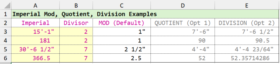
...Continue from previous post, experiment with imperial mod, quotient, division. ##********************************************************************************************** ## 45 UDF/ Excel name: impaMQD() - Similar Excel MOD() function with optional parmeters, ## return quotient or division [opt_1Quotient_or_2Division]. ## ## Note: This function uses todec() & toimpa() as sub-functions. ## ## Notes with optional parameters: ## ## [opt_1Quotient_or_2Division] = 1 , Similar Excel QUOTIENT() function - Returns the integer ## portion of a division ## [opt_1Quotient_or_2Division] = 2 , division calculation (varDividend/varDivisor) ## ## Optional parameters other than 1 & 2 will return error #N/A ## ## Rev. 1.0 - 9/2/2025 ##********************************************************************************************** =LAMBDA(varDividend,varDivisor,[opt_1Quotient_or_2Division], LET(optN,IF(ISOMITTED(opt_1Quotient_or_2Division),0, IF(AND(opt_1Quotient_or_2Division<=2,opt_1Quotient_or_2Division>0),opt_1Quotient_or_2Division,NA())), varD1,todec(varDividend), varD2,todec(varDivisor), answrM,varD1-(varD2*INT(varD1/varD2)), answrQ,ROUNDDOWN(varD1/varD2,0), answrD,varD1/varD2, SWITCH(TRUE, optN=0,IF(AND(ISNUMBER(varDividend),ISNUMBER(varDivisor)),answrM,IF(OR(AND(ISTEXT(varDividend),ISTEXT(varDivisor)),ISNUMBER(varDivisor)),toimpa(answrM),"Error!")), optN=1,IF(OR(AND(ISNUMBER(varDividend),ISNUMBER(varDivisor)),AND(ISTEXT(varDividend),ISTEXT(varDivisor))),answrQ,IF(ISNUMBER(varDivisor),toimpa(answrQ),"Error!")), optN=2,IF(OR(AND(ISNUMBER(varDividend),ISNUMBER(varDivisor)),AND(ISTEXT(varDividend),ISTEXT(varDivisor))),answrD,IF(ISNUMBER(varDivisor),toimpa(answrD),"Error!")), NA() ) ) )
-
Or just call MULTIPLE before calling APV.
-
Since Lee's Code only has you picking a point its easy enough. Just add a call at the end of APV (line 95) to call itself again. This will force a loop that you have to hit esc to exit. - Edit This is a better option. Has undo marks. You could also set your snaps before entering the command if you want to. ;;----------------------------------------------------------------------------;; ;; Add Polyline Vertex loop ;; Dependent AddLWPolylineVertexV1-1.lsp (defun C:APVL ( / ) (vl-load-com) (princ "\nStarting Add Polyline Vertex loop. Press ESC to stop.") (vla-StartUndoMark (setq doc (vla-get-ActiveDocument (vlax-get-Acad-Object)))) ;(setvar 'OSMODE 3) ;End and mid point snaps (while T (C:APV) ) (princ "\nAdd Polyline Vertex Loop ended.") (vla-EndUndoMark doc) (princ) )
-
 C3D-10086 joined the community
 -
So is your question really how to make these loop, keep picking points until you hit enter or escape?
-

Penn Foster Student Suffering with Oleson Village Map!!!
ReMark replied to AutoCad Student's topic in Student Project Questions
That title does not ring a bell. Are you referring to the Oleson Village Project specifically or another project? -
Thanks Lee yes during testing had a stuck loop a few times had to crash out CAD. Will use the full defun rather than the short version.
-

Extracting data to excel from selected objects on different layers
BIGAL replied to Hsanon's topic in AutoLISP, Visual LISP & DCL
@kidznok Check your PM -
Update found this from gile https://forums.augi.com/showthread.php?68868-Adding-vertexes-to-a-polyline&p=765721&viewfull=1#post765721 can it be modified so i can pick multiple points until I exit?
-
Does anyone have a lisp that can add multiple vertex for polyline? I found this Lisp from the great @Lee Mac and it works except that I need to be able to pick simultaneously even if it does not reside on the line then hit escape or enter when done. I will then move the added vertex to its proper location.
-
Type GRAPHICSCONFIG → Enter → Advanced Settings → uncheck “Fade inactive geometry” (or slide it to 0%) → Apply → OK. That’s it. Your prints will instantly look exactly like they did in AutoCAD 2022 – no more extra faint lines.
- Last week
-
You're missing the double backslash ("*\\P*") Also, note that the use of vl-string-subst with a constant starting position and wcmatch to test the content is dangerous in general as this will result in an infinite loop if the replacement string contains the find string, e.g. consider replacing "new" with "knew" - your code would loop indefinitely.
-
Automating Room Quantities? I built a Lisp for that (Free v1.0)
BIGAL replied to kevren's topic in AutoLISP, Visual LISP & DCL
Is it exporting to Excel direct or are you using the CSV ? I have a libre Calc output as well. -
Thanks everyone, the answer sometimes is just looking at you and waving back. Need to double check help in future. (while (wcmatch txt "*\P*") (setq txt (vl-string-subst "\n" "\\P" txt 1)) ) Screen Recording 2025-11-24 093452.mp4